Project
Aim :- Carry out system level simulation on an All Terrain Vehicle.
Objective :- To prepare a technical report explaining the BAJA model properties.
Theory :-
All Terrain Vehicle ,
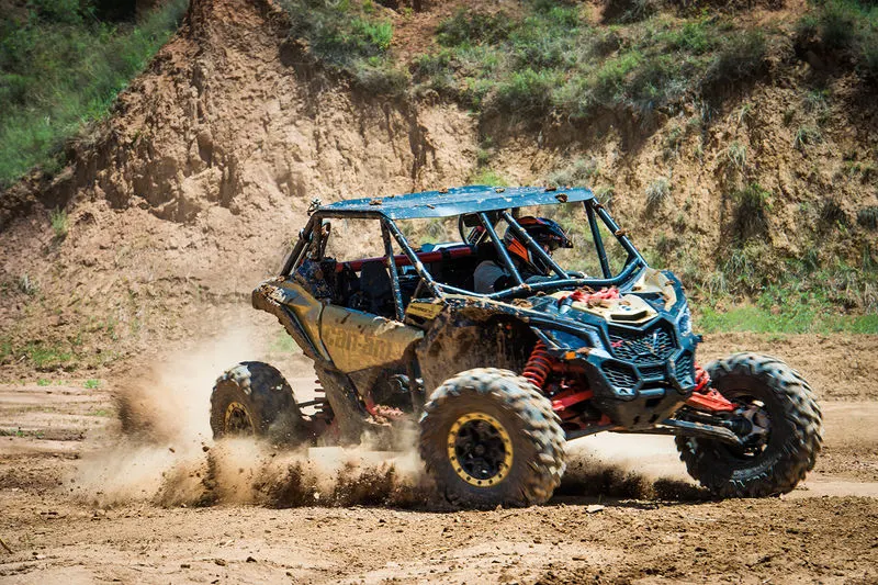
All-Terrain Vehicles (ATVs) are a class of multi-wheeled vehicles; the most common types are 3- and 4-wheel machines. 4-wheel ATVs may be referred to as “quads”. Some, like the Argo, come with 6 or 8 wheels and are amphibious.Handling an ATV is very different from other vehicles, including 2-wheel motor bikes. Operatingan ATV is “rider active” where the rider must use his or her body movements to help control the machine. The all-terrain design creates a higher centre of gravity and makes these machines more susceptible to overturning, particularly on corners or at high speeds. ATVs should not be operated without adequate instruction from a certified or experienced instructor. As ATVs are designed for off-road use and are permitted on public roads in only a few regions, riders should be familiar with local ATV regulations. The use of ATVs is increasing as they allow access to areas that might otherwise be too remote or too costly to reach. They provide a convenient means of carrying equipment, supplies and samples, and may even replace pack animals in some places. However, they are not the safest off-road vehicle and they should only be used when necessary. When off-road conditions are suitable for their use, it is advisable to use four wheel drive vehicles and side by side utility vehicles, which are generally safer than ATVs.
Study 1 :
Case 1,
Simulink model for BAJA ATV with CVT :-
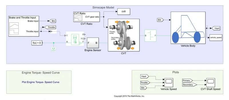
Above BAJA ATV model is created using simulink and simscape blocks.
Main components used are CVT,Engine Sensor,Signal Builder,Vehicle body,Generic Engine and Simple Gear.
CVT Gear box :-
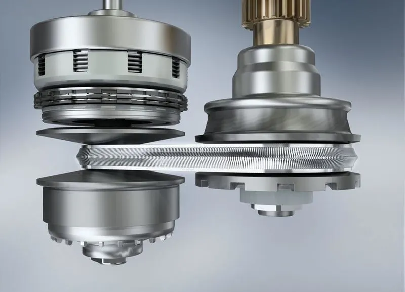
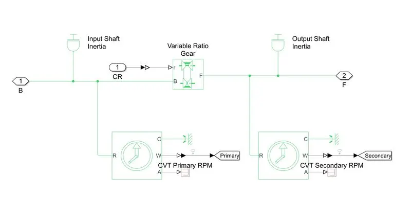
While a traditional transmission uses a wide variety of intricate parts to shift between a range of preset gears, most CVT systems work through a pulley system. In short, this system consists of cones at each pulley connected via a chain belt. The cones can move to increase or decrease the belt diameter to change gear ratios, allow for quick shifting into the needed ratio for increased power, and boost fuel economy.One pulley in the CVT is connected to the engine and the other directs power to the wheels. The width of these pulleys changes based on the needed power; as one gets larger, the other gets smaller. This allows a CVT to deliver strong and seamless acceleration.
CVT Block :-
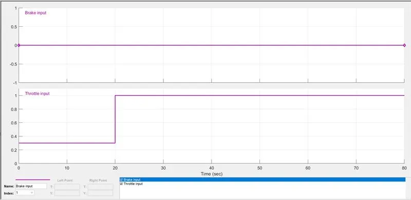
Signal Builder :- Signal Builder block allows you to incorporate test cases as a signal source in your model. Using the Signal Builder block you can: Graphically create and tweak signals using the signal builder interface. Manage groups of input signals, each corresponding to a simulation run.
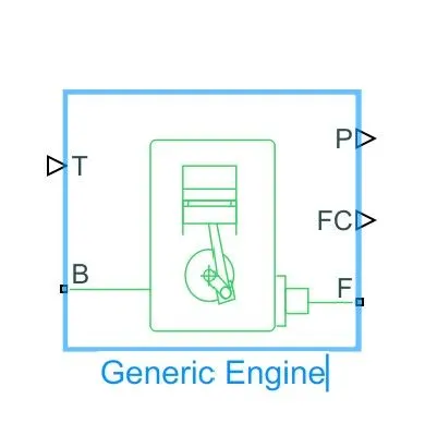
Generic Engine :- Engine block uses a programmed relationship between torque and speed that is modulated by the throttle signal. The block evaluates engine power demand as a function of engine speed, g (Ω). The function provides the maximum power available for a given engine speed, Ω.
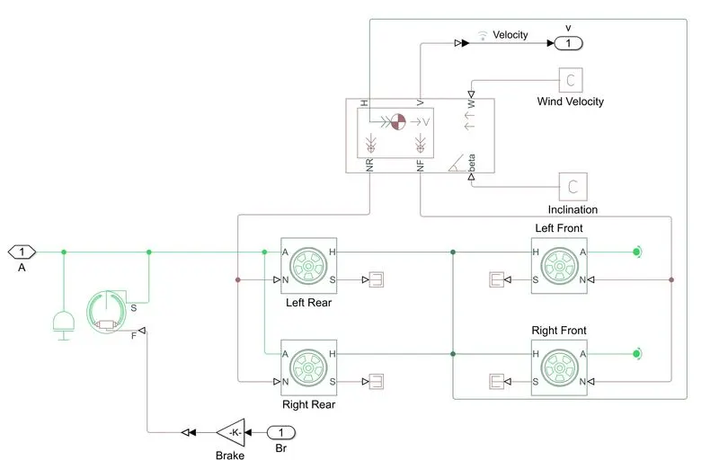
Vehicle Body :- Vehicle body block represents the two axel vehicle body in longitudinal motion.The block accounts for body mass,aerodynamic drag,road incline,and weight distribution between axis due to acceleration and road profile.The vehicle can have the same or a different number of wheels on each axel.Optionally include pitch and suspension dynamics or additional variable mass and inertia.The vehicle does not move relative to the ground.
Input Signals Using Signal Builder For Brake and Throttle,
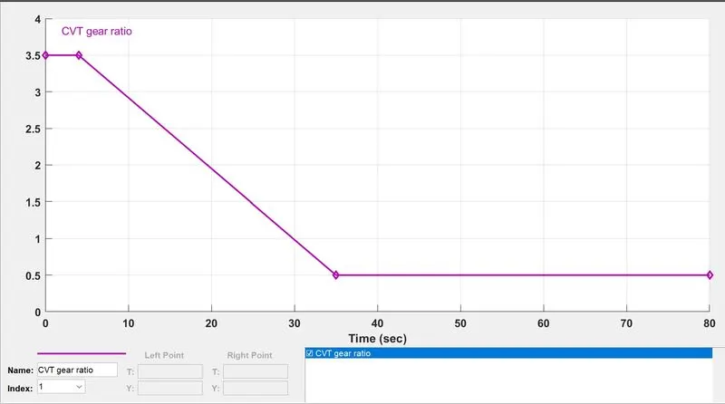
Input for CVT Gear Ratio,
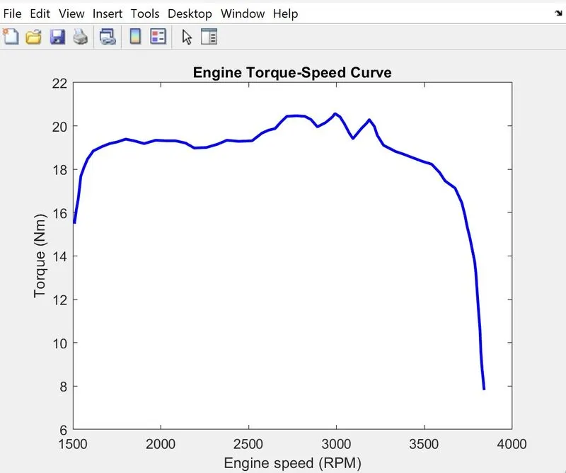
Torque vs Engine speed input,
Case 1 Output :
Vehicle Speed,
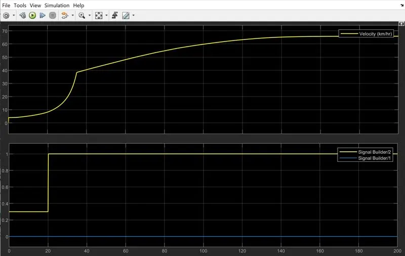
As we can see from the graph that vehicle attains its maximum speed at 65 km/hr and then remains constant.The brake input is zero hence there is no change in the graph as well.
CVT Gear Ratio,
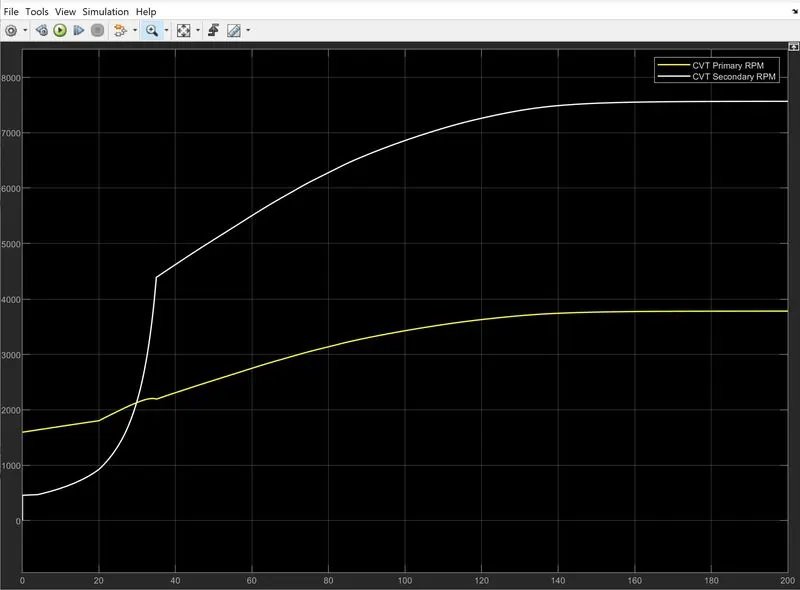
Above graph shows the variation in the input and output shaft of the variable gear transmission system.
Case 2,
Studying the BAJA ATV using CVT and Dashboard,
This model is similar to the previous model but only major difference here is that we can change throttle and brake position or their values according to us.It provided with two knob one for Throttle position and another one for the Brake position and as we change the values its getting showed in the gauge which is interface with the knob.
Model:
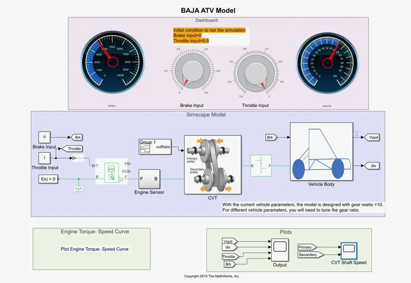
In the above cvt dashboard model we provide the the value for brake knob is zero and the velocity is around 60 km/hr.
The output we get in the scope is shown below.
Output CVT Dashboard ,
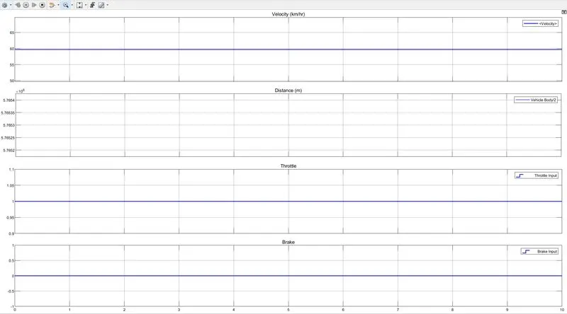
Output Shows CVT primary and secondary RPM,
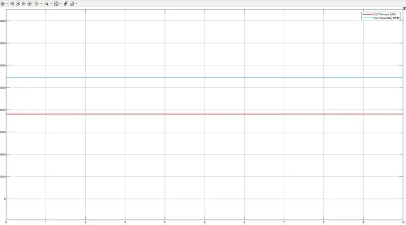
Here in CVT the radius of the primary shaft is more than the secondary shaft and the speed is truly dependent on the shaft.
As the radius increases the speed of the shaft is also increases.
Study 2 :
Case 1,
Study of BAJA ATV model using CVT and Look up table :
Look up table,
A look up table is an array of data that maps input values to the output values,thereby approximating the mathematical function.Gives a set of input values a look up operation retrives the corresponding output values from the table.If the look up table does not explicitly define the input values,simulink can estimate an output value using interpolation,extrapolation or rounding.
Interpolation : It is process for estimating the values that lie between known data points.
Extrapolation : It is process for estimating the values that lie beyond the range of known data points.
Rounding : It is a process for approximating a value by altering its digits according to the known rule.
Model,
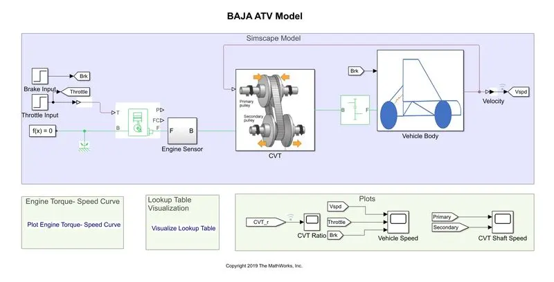
The difference between with look up table and without look up table that here the gear ratio input provided to the cvt subsystem is using look up table.Input of throttle and brake is provided with the help of step block
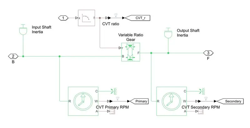
Look up table visualization,
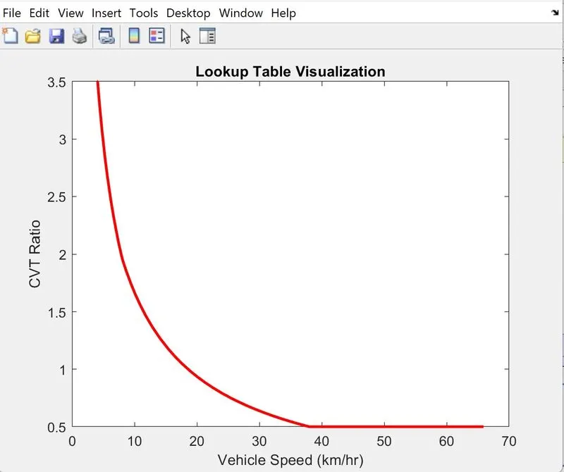
Gear ratio feed through the look up table which takes input to cvt and works as closed loop when input is given to the look up table.
The simulink gets the input from the look up table and shows the output relevant to the look up table input.Here the gear ratio
varies from 3.5 to 0.5 which is taken as input.
Output :-
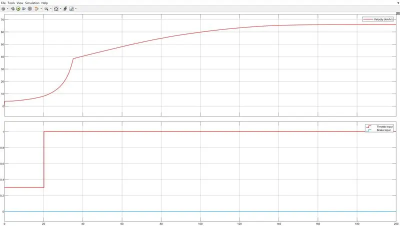
In the above graph as you can see brake input is constant which is zero and throttle is increasing which is also increasing velocity.
Here the given input is provided through the look up table.
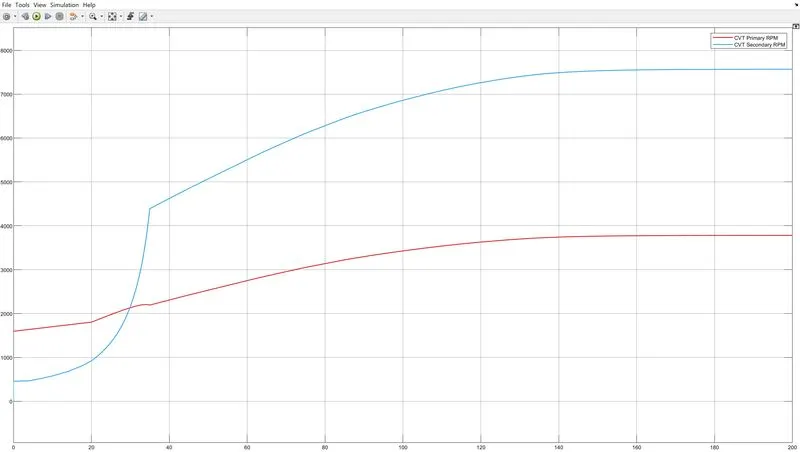
In above figure as we can see throttle value increases the flow of fuel increases which result in the increased power of the engine.The radius of the primary shaft is more than the secondary shaft and vehicle speed is directly depend on the radius of shaft.
Case 2,
Study of CVT ATV model using look up table and dashboard :
Model,
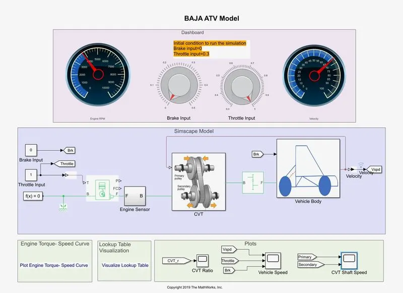
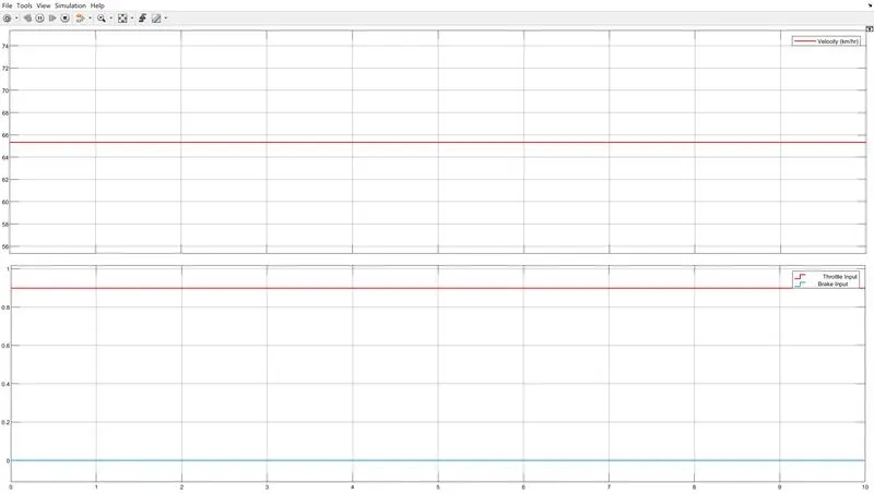
In the above CVT model we give the input throttle value is around 0.9 and brake input is 0 which is constant throughout.The output velocity and engine RPM we can see through the scope.Foe the given input value the velocity is 65 and engine RPM is 3800 which we can see using scope. The images shown below will give clear idea to us about the output.
Output,(Throttle,Brake)
Output(RPM),
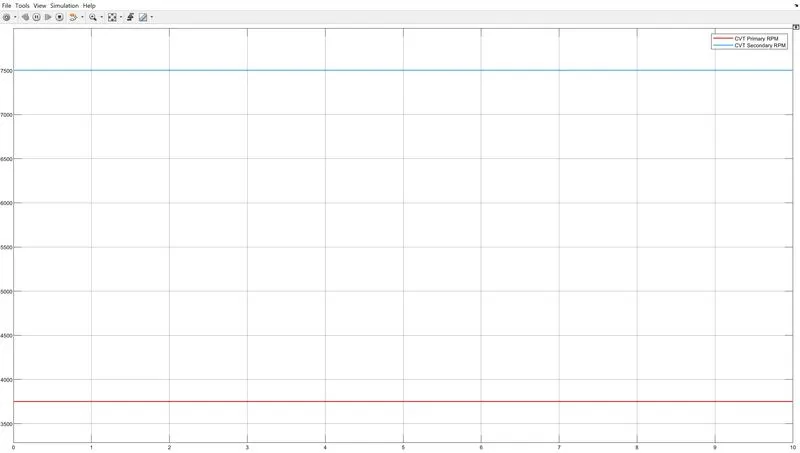
In the above figure primary and secondary RPM is shown using scope.The primary shaft reaches to the lower RPM which is due to its bigger radius as compared to the secondary RPM.Secondary RPM catches greater values due to its smaller radius with respect to the secondary shaft.These values can differ using different gear ratio.
Conclusion :-
From the above BAJA ATV model we can see that Throttle can directly affect the engine RPM due to the difference of fuel flow towards the engine.Using Look up table and Dashboard we can also see the different output with respect to the different values which is provided.