Project
AIM
Carry out a system-level simulation of an all-terrain vehicle.
OBJECTIVE
To carry out a simulation and technical report on BAJA ATV.
Explain model properties for
- With and without a dashboard.
- With and without a lookup table.
THEORY
ATV
- ATV means an all-terrain vehicle that is specially designed for off-road driving. ATV is designed for very rough terrain, jumps, maneuverability, and endurance. It has applications across various industries, including sports, entertainment, agriculture, military, and defense.
- Components of ATV are vehicle body, suspension, tire, engine & continuously variable transmission system.
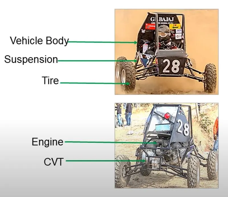
figure .a ATV
CVT
- A continuously variable transmission is an automatic transmission that can change seamlessly through a continuous range of gear ratios. This contrasts with other transmissions that provide a limited number of gear ratios in fixed steps. The flexibility of a CVT with suitable control may allow the engine to operate at a constant RPM while the vehicle moves at varying speeds.
- The most common type of CVT uses two pulleys connected by a belt or chain. The pulleys consist of two cone-shaped halves that move together and apart. The v-belt runs between these two halves. So the pulley’s effective diameter depends on the distance between the two halves of the pulley. The V-shaped cross-section of the belt causes it to ride higher on one pulley and lower on the other. Therefore the gear ratio is adjusted by moving the two sheaves of one pulley closer together and the two sheaves of the other pulley farther apart.
- As the distance between the pulleys and the length of the belt does not change, both pulleys must be adjusted (one bigger, the other smaller) simultaneously in order to maintain the proper amount of tension on the belt. Simple CVT combining a centrifugal drive pulley with a spring-loaded driven pulley often uses belt tension to affect the conforming adjustments in the driven pulley.
- The V-belt needs to be very stiff in the pulley axial direction in order to make only short radial movements while sliding in and out of the pulleys. The radial thickness of the belt is compromised between the maximum gear ratio and torque.
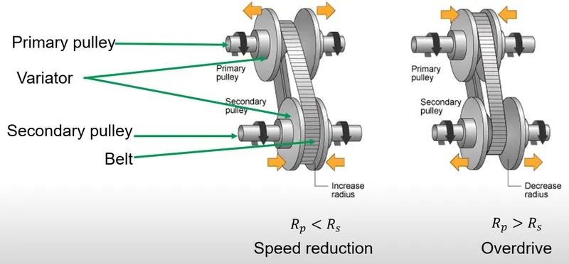
figure .b CVT
click here for -BAJA ATV model simulation files google drive link
MODEL-1
BAJA ATV model
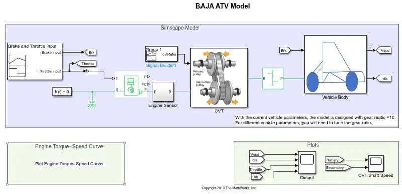
figure 1.1 BAJA ATV model
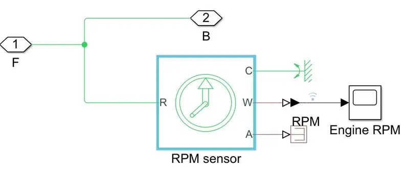
figure 1.2 Engine sensor subsystem
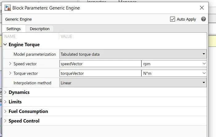
figure 1.3 generic engine settings
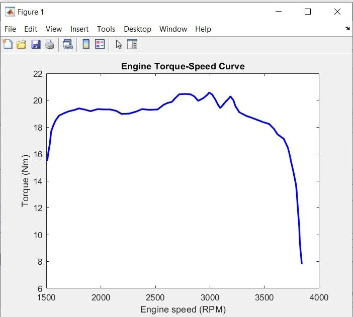
figure 1.4 Engine torque-speed curve
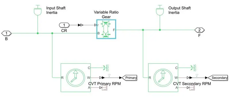
figure 1.5 CVT subsystem
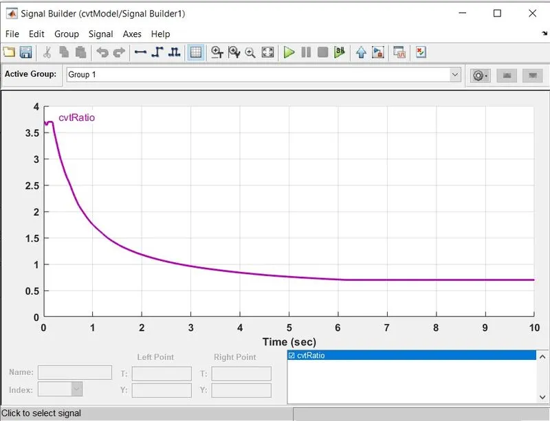
figure 1.6 cvt ratio signal
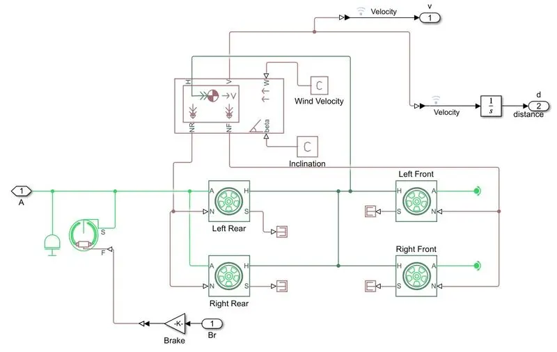
figure 1.7 vehicle body subsystem
EXPLANATION
- BAJA ATV model consists of signal builder of brake and throttle input, generic engine, CVT, simple gear, and vehicle body.
- Signal builder provides input of brake and throttle. Throttle input is connected to the generic engine’s T port and brake input is connected to the goto block.
- For generic engine F and B ports are mechanical rotational conserving ports associated with the engine crankshaft and engine block, respectively. Here mechanical rotational reference and solver configuration are connected to the B port of the generic engine.
- Generic engine is connected to CVT block through engine sensor subsystem block. The engine sensor subsystem contains an ideal rotational motion sensor, which measures angular velocity.
- In generic engine settings needs speed vector and torque vector value. Here speed vector and torque vector data are preloaded through call-back settings. Here also provided the engine torque- speed curve. We can extract the data points using the image of the torque-speed curve through the GRABIT program.
- CVT block contains input shaft inertia, output shaft inertia, variable-ratio transmission block, and ideal rotational motion sensor.
- Here input shaft inertia and output shaft inertia block represents primary and secondary pulley respectively.
- Variable ratio transmission block represents a variable gearbox implemented by mechanical belt CVT. The physical signal r defines the ratio of input to output angular shaft velocities.
- Here port r connects to signal builder, which provides the CVT ratio and ideal rotational motion sensors are provided for measuring the speed at the primary and secondary pulley.
- CVT is connected to the vehicle body subsystem through simple gear to reduce the speed. Where simple gear represents a fixed ratio gear and the gear ratio is set to 10.
- Vehicle body subsystem consists of vehicle body block, tire (magic formula), double shoe-brake.
- Vehicle body block represents a two-axle vehicle body in longitudinal motion. Providing mass and center of gravity position. Here port H is the mechanical translational conserving port associated with the horizontal motion of the vehicle body. The resulting traction motion developed by tires should be connected to this port. Connections V, NF, and NR are physical signal ports for vehicle velocity and front and rear normal wheel forces respectively.
- Ports W and beta are physical signal input ports corresponding to headwind speed and road inclination angle respectively. Here wind velocity and road inclination are provided zero only.
- Here tire blocks are added which are two rear tires and two front tires. Where connection A is the mechanical rotational conserving ports. The rear tire’s port A connected to the simple gear. That is the rear tire that moves the vehicle’s body. Front tires are freely rotated. Therefore front tire’s port A is connected to the rotational free end block.
- Connection H is the mechanical translational conserving port for the wheel hub through which the thrust developed by the tire is applied to the vehicle. Here all tires’ H port is connected to the H port of the vehicle body. ‘
- Connection N is a physical signal input port that applies the normal force acting on the tire. Here rear tire’s N port is connected to the NR port of the vehicle body and the front tire’s N port is connected to the NF port of the vehicle body.
- Connection S is a physical output port that reports the tire slip. Here tire slip is not measured, so all tire’s S port is connected to the PS terminator block.
- Double shoe brake arranged as two pivoted rigid shoes symmetrically installed inside or outside the drum and operated by one actuator. The actuator force causes the shoe to exert friction torque on a shaft connected to the drum. Connection S is a conserving rotational terminal associated with the drum shaft. Which is connected to the rear tire’s A port.
- Connection F is a physical signal port representing the force input to the actuator. Positive force creates friction torque that resists shaft rotation. Here F port is connected to break input through a gain block of the gain value is 1000.
- Here an inertia block is provided which represents ideal mechanical rotational inertia.
- Vehicle body outputs velocity and it is again integrated to get distance value.
RESULT
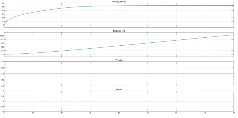
figure 1.8 output scope view
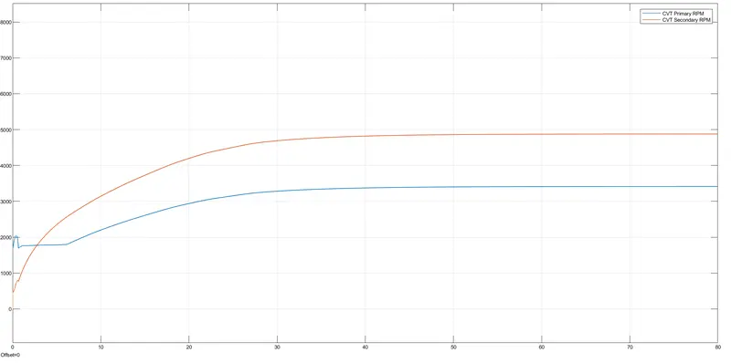
figure 1.9 CVT shaft speed scope view
- Output scope gives the velocity, distance, throttle, and brake graph. Here brake input is zero. That is brake graph shows a straight line of the value of zero.
- Constant throttle of 0.5 is provided. As the distance increases the velocity increases and reaches 50 km/hr after 40 sec and maintains that velocity.
- Where CVT shaft speed scope gives primary and secondary pulley speed in rpm. The graph shows that the speed of the secondary pulley is higher than the primary pulley.
MODEL-2
BAJA ATV model with dashboard
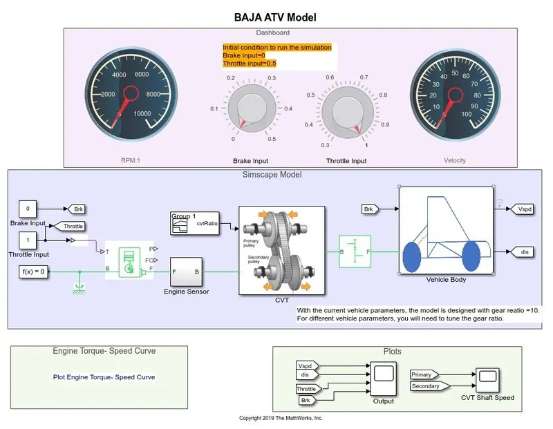
figure 2.1 BAJA ATV model with dashboard
EXPLANATION
- This model is similar to the above model except for that model with a dashboard containing knobs and circular gauges.
- Knob is used to control brake input and throttle input. Here the brake input and throttle input are constant blocks that are connected to the knob,
- Two circular gauges are provided, one is used for measuring engine RPM and the other is used for measuring vehicle velocity.
RESULT
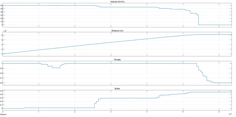
figure 2.2 output scope view
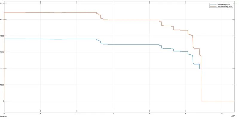
figure 2.3 CVT shaft speed scope view
- The output scope gives velocity distance, throttle, and brake graph details.
- Initially, the brake value is zero and throttle value is 1 and the velocity of the vehicle reached 60km/hr instantly and the further brake is applied slightly, which is increasing the brake input and also decreasing the throttle input. Eventually, the vehicle body stops and velocity became zero.
- CVT shaft speed scope shows that primary and secondary pulley speed variation.
MODEL-3
BAJA ATV model with lookup table
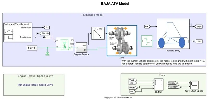
figure 3.1 BAJA ATV model with lookup table
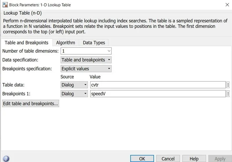
figure 3.2 Lookup table
EXPLANATION
- It is a BAJA ATV model with a lookup table. Here CVT ratio is provided in the lookup table instead of using the signal builder block. Here lookup table uses data of speed v and cvtr values, which are engine speed in RPM and CVT ratio, respectively.
- These data are provided by call-back settings. Here lookup table gives the CVT ratio to the variable ratio gear corresponding to the engine rpm gives input to the lookup table block.
RESULT
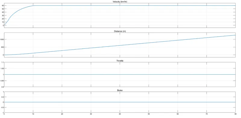
figure 3.3 output scope view
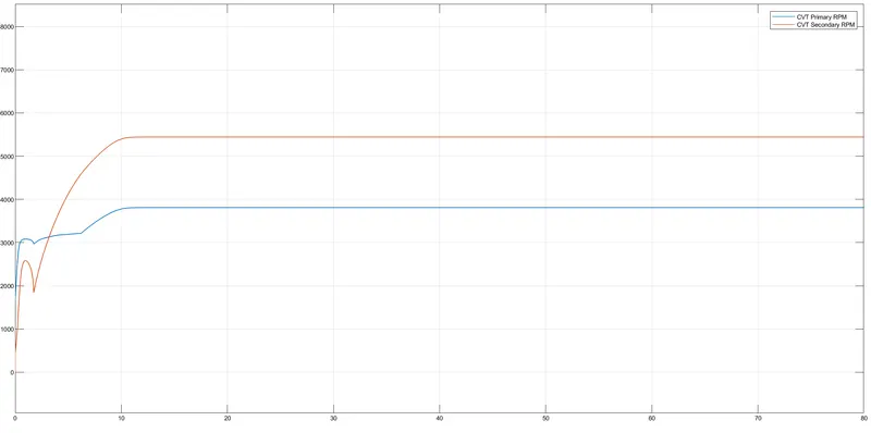
figure 3.4 Cvt shaft speed scope view
- Here brake input is zero and throttle is one throughout the time.
- Output scope gives velocity, distance, throttle, and brake.
- In velocity graph shows that at 10 sec the velocity of the vehicle reached to a maximum of 60 km/hr and remain constant throughout the time.
- Cvt shaft speed scope gives the primary and secondary pulley speed in rpm.
MODEL-4
BAJA ATV model with lookup table
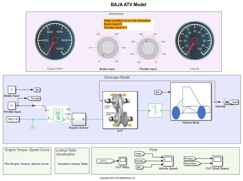
figure 4.1 BAJA ATV Model with lookup table
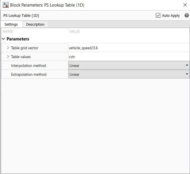
figure 4.2 Lookup table
EXPLANATION
- Here model with a lookup table and its variables are vehicle_speed and cvtr. Where vehicle_speed and cvtr are variables that are preloaded by call-back settings.
- Lookup table visualization also provided with a link and it gives a graph of cvt ratio and vehicle speed. Here lookup tables provide CVT ratio to the variable ratio gear based on the vehicle velocity feedback system.
RESULT
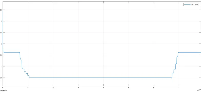
figure 4.3 CVT ratio scope view
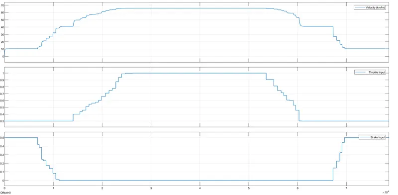
figure 4.4 Output scope view
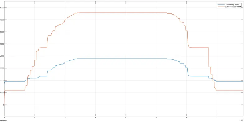
figure 4.5 Cvt shaft speed scope view
- Vehicle speed scope gives the velocity of vehicle change as per brake input and throttle input.
- Cvt shaft speed scope gives the primary and secondary pulley speed in rpm.
- Cvt ratio scope gives cvt ratio changes as per vehicle speed with respect to time.
CONCLUSIONS
- Simulation of BAJA ATV models are carried and results are provided as per inputs.
REFERENCE
https://www.mathworks.com/matlabcentral/fileexchange/70576-baja-all-terrain-vehicle-atv-model