Project 5
AIM: For a 10 cell series, calculate the voltage, current and SOC. Also simulate the aging and thermal effects at different charge and discharge rates. Comment on the battery pack’s capacity.
SIMULINK MODEL:
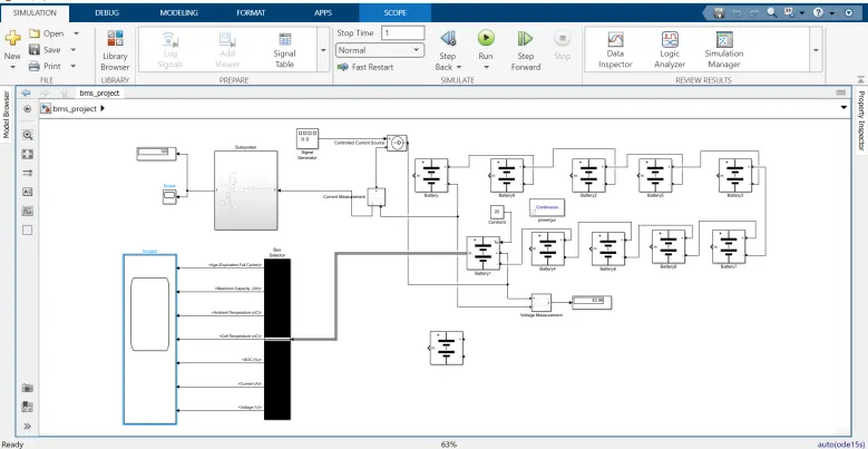
The above fig shows the 10 cell series lithium ion battery model.These are all battery cells connected in series.This battery pack charges and discharges by using the controlled current source and signal generator block. For this cell enables the temperature effect option for observing and estimating the temperature effect signal effects. So in this model we estimate the SOC of the battery pack,battery pack temperature i.e. ambient temperature, battery pack current by using Scope connected to the battery pack.
So, ambient temperature & SOC of the cell is similar to other cells.The battery pack voltage is calculated by using a voltage sensor block is connected across the battery pack terminals, first cell positive terminal connected to the positive terminal of voltage measurement block and last cell negative terminal connected to negative terminal of voltage sensor block.current measurment is connected in series and SOC.Bus selector is connected to last battery out put to give value to the scop
BLOCKS USED:
1)powergui
2)Battery
3)bus selector
4)voltage measurment
5)current measurment
6)signal generetor
7)controlle current source
1)POWER GUI:
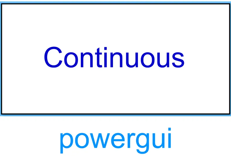
The powergui block allows you to choose one of these methods to solve your circuit Continuos ,which uses a variable-step solver from Simulink Discretization of the electrical system for a solution at fixed time steps Continuous or discrete phasor solution The powergui block also opens tools for steady-state and simulation results analysis and for advanced parameter design
2)BATTERY:
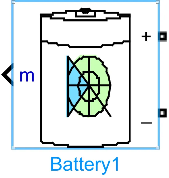
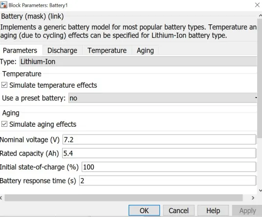
we use lithiam-ion battery in module which use for implement a generic modelfor most popular battery types.Temprature and aging effects can be specified.
3)BUS SELECTOR:
Bus selector block is used to split vector signals into scalars or smaller vectors. Check 'Bus Selection Mode' to split bus signals.
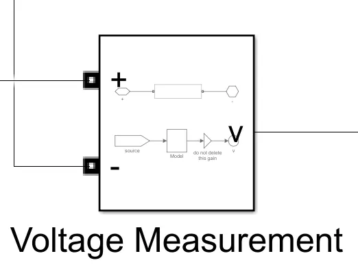
4)VOLTAGE MEASUREMENT:
This block represents voltage measurement used to measure the voltage across the connected terminals
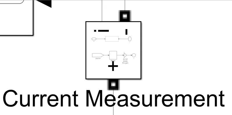
5)CURRENT MEASUREMENT:
This block is use to measure ampere(current) value. current measurment block is always connected in series.
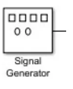
6)SIGNAL GENERATOR:
The Signal Generator block can produce one of four different waveforms:
- Sine
Square
Sawtooth
random
We can express signal parameters in hertz or radian/sec
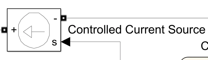
7)CONTROLLED CURRENT SOURCE:
The Controlled Current Source block converts the Simulink input signal into an equivalent current sour The generated current is driven by the input signal of the block. The positive current direction is as shown by the arrow in the block icon. We can initialize the Controlled Current Source block with a specific AC or DC current. If you want to start the simulation in steady state, the block input must be connected to a signal
starting as a sinusoidal or DC waveform corresponding to the initial values
Case 1:
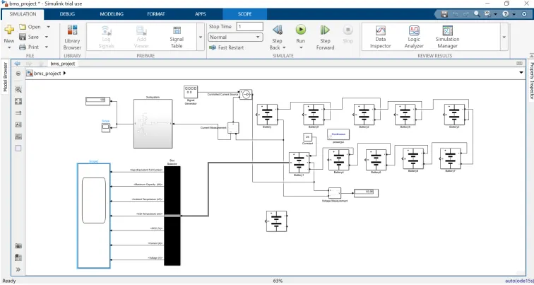
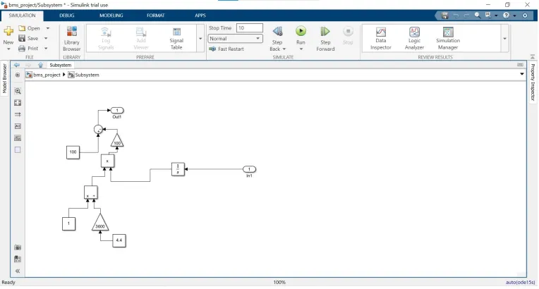
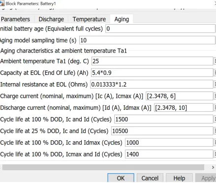
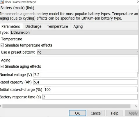
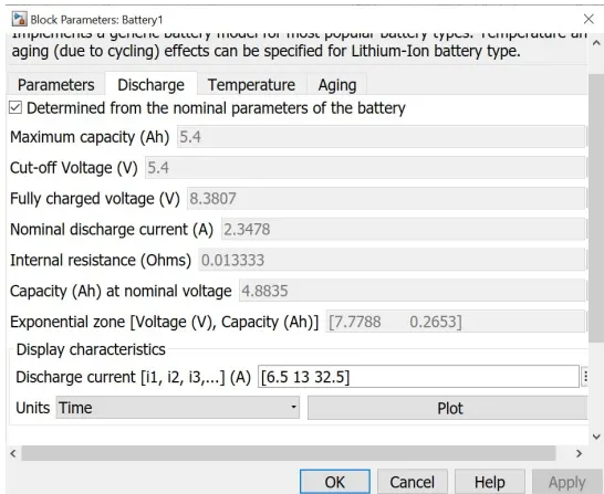
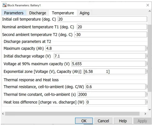
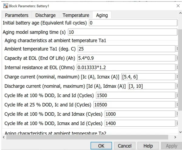
10 cells connected in series a one single battery voltage is 7.2v current 5.4A and the charging and discharging time of battery pack is degault valu 2.3478,6 and 2.3478, 10. the ambiant temprature of the battery is 25 and SOC rate is 100per for Soc build a sepret subsystem shown as above image the cell capacity is set 4.4 and gain sec is 1/3600 and soc is 100per as per formula.
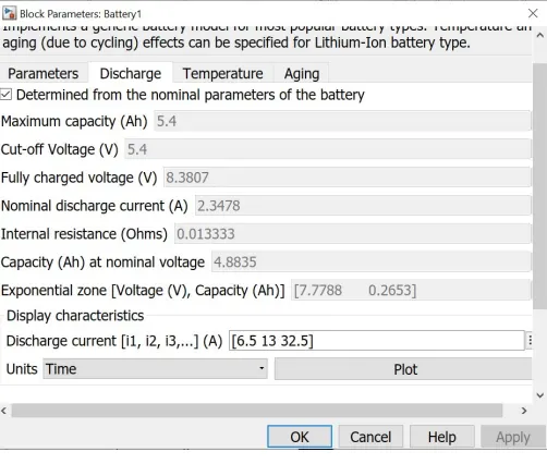
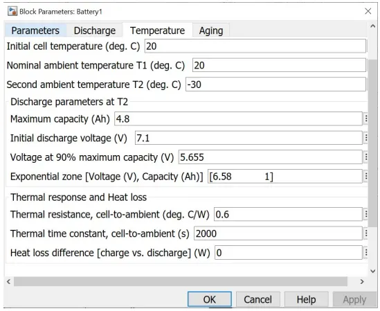
When we run thise module by puting all valuse the out put valuse reflect in scope as shown in
below image
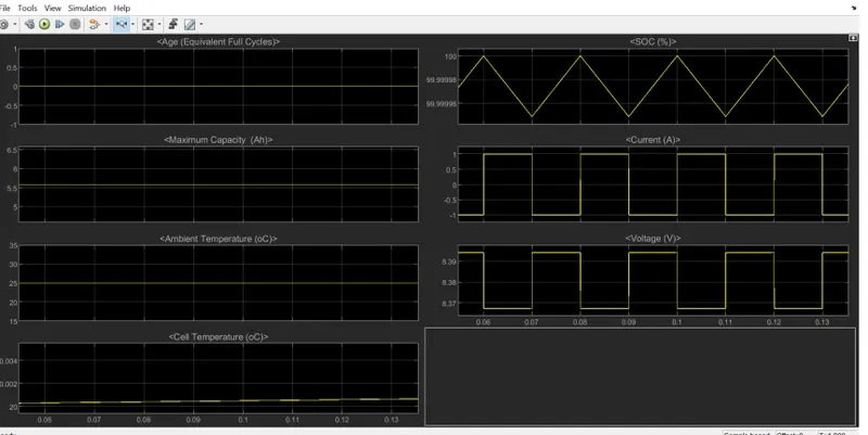
Case 2:
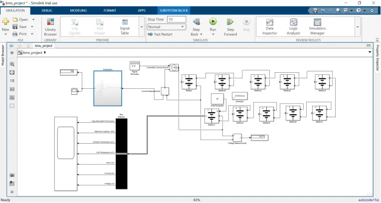
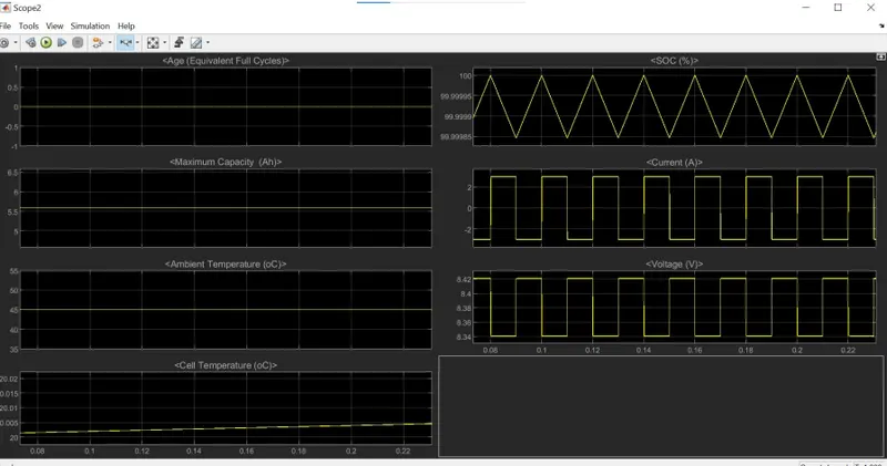
In thise case the battery voltage and current is same 7.2V and 5.4A but charging and discharging current is change charge current is 5.4 and Discharge current is 3 and ambient tempreture of the battery is set to be 45 and other blocks parameters is same SOC is 100persent as shown on below image.
when we run this module scope show result change ambeant tempreture sho 45 current in 2 to
-2 range voltage is 83V and Soc is 99.98 per
CONCLUSION:
We have succesfully complete the given task
- When we increase the ambient temperature then obviously cell temprerature increased also this ambient temperature adverse effect reflects on the age of the battery pack and vice versa.
- Similarly when we decrease C rate then shows the favourable and unfavourable effects on the age, SOC, temperature and voltage of the battery pack