Week-7 Challenge: DC Motor Control
QUESTION 1:
AIM: A. Explain a MATLAB demo model named ‘Speed control of a DC motor using BJT H-bridge’.
B. Comment on the armature current shoot-up from the scope results.
C. Refer to the help section of ‘The Four-Quadrant Chopper DC Drive (DC7) block’. Compare it with the H-bridge model.
A)SPEED CONTROL OF DC MOTOR USING BJT H-BRIDGE:
The Bipolar Junction Transistor (BJT) when used for power switching applications, operates as an IGBT. When it is conducting (BJT operating in the saturated region), a forward voltage Vf is developed between collector and emitter (in the range of 1 V). Therefore, the IGBT block can be used to model the BJT device.The IGBT block does not simulate the gate current controlling the BJT or IGBT. The switch is controlled by a Simulink® signal (1/0). The DC motor uses the preset model (5 HP 24V 1750 rpm). It simulates a fan type load (where Load torque is proportional to square of speed). The armature mean voltage can be varied from 0 to 240 V when the duty cycle (specified in the Pulse Generator block) is varied from 0 to 100%.
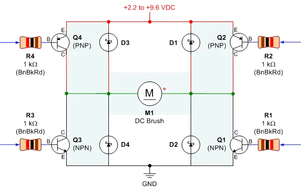
The H-bridge consists of four BJT/Diode pairs (BJT simulated by IGBT models). Two transistors are switched simultaneously: Q1 and Q4 or Q2 and Q3. When Q1 and Q4 are fired, a positive voltage is applied to the motor and diodes D2-D3 operate as free-wheeling diodes when Q1 and Q4 are switched off. When Q2 and Q3 are fired, a negative voltage is applied to the motor and diodes D1-D4 operate as free-wheeling diodes when Q2 and Q3 are switched off.
SIMULINK MODEL OF BJT H-BRIDGE:
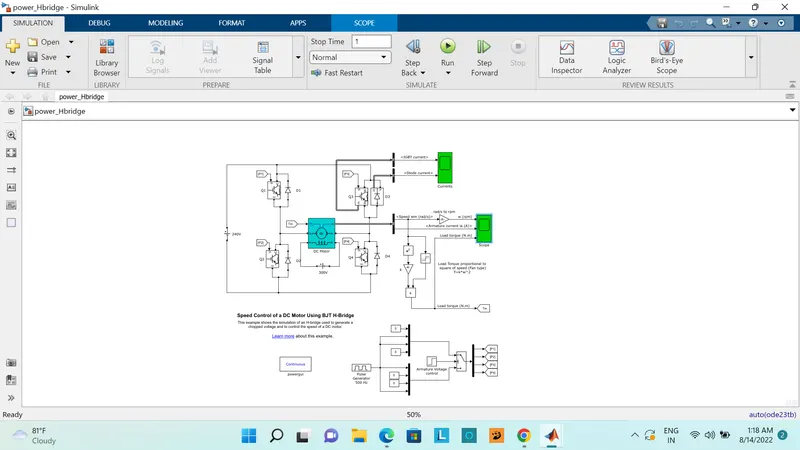
PROCEDURE OPEN BJT H-BRIDGE:
1)Open the MATLAB file and in that open the simulink option above the dispay
2)than the simulink software will be popup in that choose blank model
3)in the simulink software right side you got the help option than click it
4)in the search barch you have to search the corresponding block model
5)now we get the bjt h-bridge block than it runs as it is
6)after that open the scope observe the waveforms
OUTPUT RESULTS:
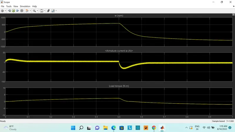
for observing the above output we get the speed of motor,armature current,load torque
SPEED OF MOTOR:
- Initially the plot increase from 0 to max 900 rpm (Forward motoring action takes place).
- Then again it reduces from 900rpm to 0 intial condition when Forward dynamic breaking action takes place.
- after the reduction of speed again it increase from 0 to 900rpm when Reverse motoring action takes place.
LOAD TORQUE:
- Initially the torque increase from 0 to 0.5 secs in forward motoring action.
- Then after torque reduces from peak to 0 Nm in forward dynamic breaking mode.
- Then torque increases in reverse direction in reverse motoring action upto 1 sec.
B)ARMATURE CURRENT SHOOT UP IN MOTOR:
Due to the sudden increase in voltage takes place initial current shoot up which inurns regulated by duty cycle.In this case motor driven in 75% of duty cycle.(i.e) 0.75*240= 180 V.
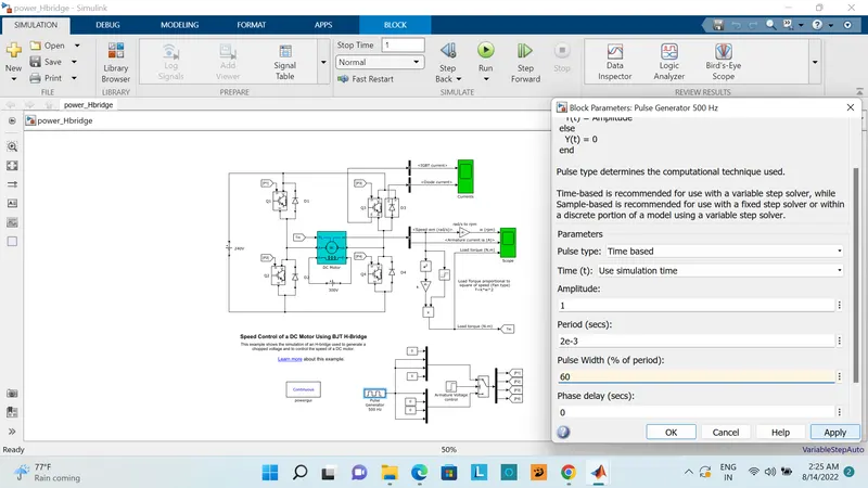
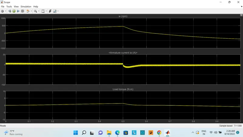
We can change the duty cycle to 60%(120 V) and seen the results as
RESULTS:
Sudden shoot up canceled in starting condition but slight shootup after 0.5 sec in reverse motoring condition.
Now we have to change the duty cycle to 40%,and observe the results
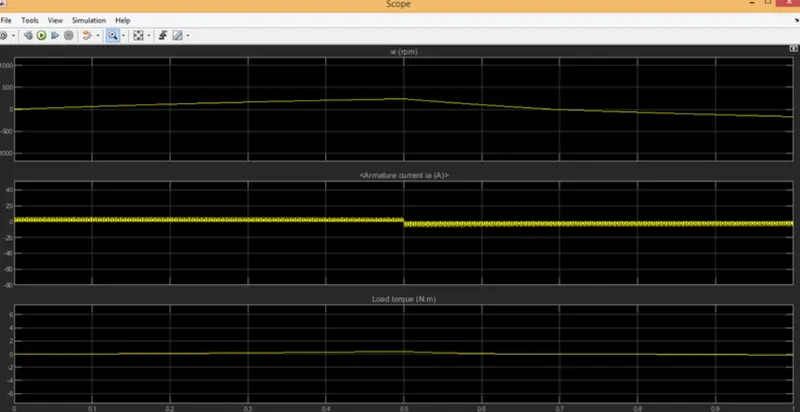
now you can observe the above plot the shoot up current should be decreasaed at both the ends
If we have to change the shoot up current first change the duty cycle gradually from minimum to maximum that inturns increases voltage gradually and speed also changes accordingly.
C) Comparing ‘The Four-Quadrant Chopper DC Drive (DC7) block’ with H bridge model:
Block:
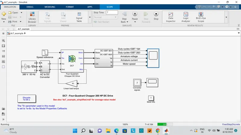
The Four-Quadrant Chopper DC Drive (DC7) block represents a four-quadrant, DC-supplied, chopper (or DC-DC PWM converter) drive for DC motors. This drive features closed-loop speed control with four-quadrant operation. The speed control loop outputs the reference armature current of the machine. Using a PI current controller, the chopper duty cycle corresponding to the commanded armature current is derived. This duty cycle is then compared with a sawtooth carrier signal to obtain the required PWM signals for the chopper.
The main advantage of this drive, compared with other DC drives, is that it can operate in all four quadrants (forward motoring, reverse regeneration, reverse motoring, and forward regeneration). In addition, due to the use of high switching frequency DC-DC converters, a lower armature current ripple (compared with thyristor-based DC drives) is obtained. However, four switching devices are required, which increases the complexity of the drive system.
SIMULINK MODEL:
WORKING OF FOUR QUADRANT CHOPPER:
- Here Four Igbt switches are used.
- Here pulses are given from PI current controller, that controles the pulses by comparing armature current measurement and current referance.
- Current referance can be generated by using regulation switch in that torque referance and PI speed controller pulses,that internally compared by speed of motor and refrance speed given as input.
- Mainly speed controlled by current controller.
- In this case Four quadrant operations are performed.
- Forward motoring mode,forward regenerative breaking mode: Q1,Q4 are on and Q2,Q3 are in off.
- Reverse motoring mode,reverse regenerative breaking mode: Q2,Q3 are on and Q1,Q4 are in off.
COMPARISION OF DC7 AND BJT H-BRIDGE:
- In DC7 chopper model speed controlled by varying current pulses from PI current controller and in H-brige model speed controlled by varying duty cycles voltages.
- Here regenerative breaking in occring while in H-bridge model breaking is occured by changing polarity of current flow,dynamic breaking occurs in it.
- In four quadrant DC chopper model smoothing inductance is used for smooth increase and decrease in current flow which inturns controlling the motor speed smoothly,while in
- H-bridge it is not present.
- Here the operation is discreat and in H-bridge model it is continuous.
- Hence 4 quadrant DC choppers are used mostly in electric vehicles.
SCHEMATIC DESIGN OF DC7:
The Four-Quadrant Chopper DC Drive block uses these blocks from the Electric Drives/Fundamental Drive Blocks library:
-
Speed Controller (DC)
-
Regulation Switch
-
Current Controller (DC)
-
Chopper
QUESTION 2:
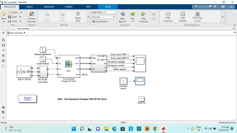
AIM: Develop a 2-quadrant chopper using simulink & explain the working of the same with the relevant results. (Refer to article - Multiquadrant operation of motor )
TWO QUADRANT CHOPPER:
a chopper may be required to provide a two quadrant operation by retaining the current direction in both motoring and braking modes. Such a Two Quadrant Chopper is shown in Fig. 3.86, and its waveforms in Fig. 3.87. The chopper permits a change in the polarity of terminal voltage keeping the direction of current constant. In Fig. 3.86 S1 and S2 are the choppers working as electronic switches and D1 and D2 are the feedback diodes. Assuming continuous conduction, both S1 and S2 operate simultaneously.
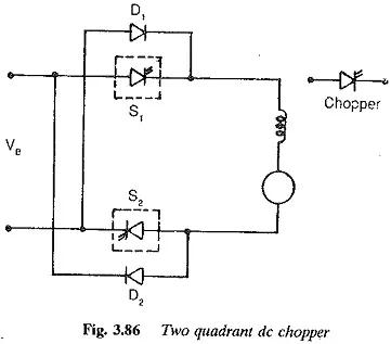
When they are ON, the load current Id increases, with the rate of rise depending upon the back emf and torque of the machine. When they are OFF, the load current is fed to the supply through the diodes D1 and D2. The current decreases in this stage. From Fig. 3.87, it is clear that the load voltage is effectively negative when the diodes conduct. The average value of the output voltage of the chopper
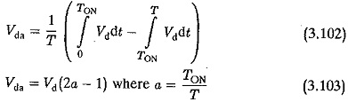
Vda is zero for a = 0.5, the output voltage is an ac waveform with average voltage equal to zero. For a > 0.5 the average value of the dc voltage is negative. The chopper works in the regenerative mode. The power flows from the load to the supply and the dc machine operates as a generator. For control ratios a c 0.5, the operation is similar to the inversion of a line commutated converter (α > 90°). For a > 0.5 the chopper has normal operation. The power flows from the supply to the load. This operation of the chopper is similar to rectification of a line commutated converter (α < 90°). For, a = 0.5 the load voltage is zero.
OPERATION OF THE SYSTEM:
- Here either one should be ON at a time,either CH1 or CH2.
- If CH1 is ON the current flows from source +ve to load(here DC motor),passes through L and E to -ve terminal of source.(1st quadrant)
- If CH1 is OFF the, FD diode conducts and complete the circuit (L-E-FD-L) as stored energy in inductor L.The voltage across is also positive voltage,current direction also positive.
- Now If CH2 is ON,Current flow from E(Load current) completes the circuit(L-CH2-E).
- If CH2 gets OFF,the current passes through D2 towards source completes the circuit(E-L-D2-+ve source- -ve source-E).
- In this stage regenerative breaking occurs.(2nd quadrant).
- This cycle continuous again upto stop time.
SIMULINK MODEL:
RESULTS:
WORKING:
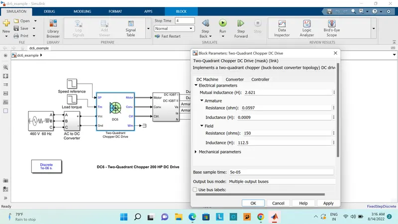
- Before starting the simulation, set the initial bus voltage to 630 V via the GUI block ('Initial States Setting' button and 'Cbus' variable).
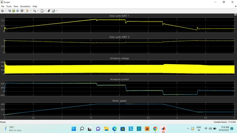
- Start the simulation. You can observe the motor armature voltage and current, the two IGBT pulses and the motor speed on the scope. The current and speed references are also shown.
- The speed reference is set at 400 rpm at t = 0 s. Initial load torque is 814 N.m.
- Observe that the motor speed follows the reference ramp accurately (+250 rpm/s) and reaches steady state around t = 2 s. The armature current follows the current reference very well, with fast response time and small ripples. Notice that the current ripple frequency is 5 kHz.
- At t = 2.1 s, the load torque passes from 814 N.m to 100 N.m. The motor speed recovers fast and is back at 400 rpm at t = 2.75 s. The current reference lowers to about 40 A to generate a smaller electromagnetic torque, the load torque being reduced. As observed before, the armature current follows its reference perfectly.
- At t = 2.75 s, the speed reference jumps down to 100 rpm. In order for the motor to decelerate following the negative speed ramp, the armature current reverses down to -160 A to generate a braking electromagnetic torque (dynamic braking mode). This causes the DC bus voltage to increase. The braking chopper limits the voltage value.
- At t = 3.4 s, the motor speed reaches 100 rpm and the current reverses back to 40 A.
- At t = 4 s, the speed stabilizes around its reference.
QUESTION 3:
AIM: Explain in a brief about operation of BLDC motor.
WORKING OF BLDC MOTOR:
A brush less dc motor (BLDC MOTOR) also known as an electronically commutated motor or synchronous DC motor using a direct current electric power supply.it uses an electronic closed looped controller to switch DC currents to the motor windings producing magnetic fields which effectively rotate in space and which the permanent magnet. A commutator-brushes arrangement helps in achieving unidirectional torque in a typical dc motor. Obviously, commutator and brush arrangement is eliminated in a brushless dc motor. Here, an integrated inverter/switching circuit is used to achieve unidirectional torque. That is why these motors are, sometimes, also referred as 'electronically commutated motors'.
BLDC motor works on the principle similar to that of a normal brushed dc motor. According to The Lorentz force law whenever a current carrying conductor placed in a magnetic field it generates some force. As a consequence of reaction force, the magnet will experience an equal and opposite force. In the BLDC motor, the current carrying conductor is stationary and the permanent magnet is moving.
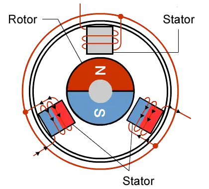
When the stator coils get a supply from source, it becomes electromagnet and starts producing the uniform field in the air gap. Though the source of supply is DC, switching makes to generate an AC voltage waveform with trapezoidal shape. Due to the force of interaction between electromagnet stator and permanent magnet rotor, the rotor continues to rotate.With the switching of windings as High and Low signals, corresponding winding energized as North and South poles. The permanent magnet rotor with North and South poles align with stator poles which causes the motor to rotate.
CONSTRUCTION OF BLDC MOTOR:
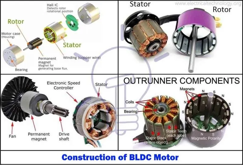
Just like any other electric motor, a BLDC motor also has a stator and a rotor. Permanent magnets are mounted on the rotor of a BLDC motor, and stator is wound with a specific number of poles. This is the basic constructional difference between a brushless motor and a typical dc motor.
MERITS OF BLDC MOTOR:
APPLICATIONS OF BLDC MOTOR:
- Computer hard drives and DVD/CD players.
- Electric vehicles, hybrid vehicles, and electric bicycles.
- Industrial robots, CNC machine tools, and simple belt driven systems.
- Washing machines, compressors and dryers.
- Fans, pumps and blowers.
CONCLUSION:
we have succesfully complete the given tasks
1)a.we are construct the model of speed control of dc motor using bjt h-bridge and also plot its graphs
b.we are done to Comment on the armature current shoot-up from the scope results.
c.we have compare The Four-Quadrant Chopper DC Drive (DC7) block and bjt h-bridge
2)we are succesfuilly develop a 2-quadrant chopper using simulink and explain its working
3)we have explain the working&construction of bldc motor