Project
AIM:- To carry out system level simulation of an all terrain vehicle (BAJA ATV) and prepare technical report explaining the model properties and the results of the simulation.
THEORY:-
What ia an ATV
An all-terrain vehicle (ATV) is defined as a motorized off-highway vehicle designed to travel on four low-pressure or non-pneumatic tires, having a seat designed to be straddled by the operator and handlebars for steering control.
What is CVT
A CVT, or continuously variable transmission, seamlessly changes through an unending range of effective gear ratios. The system consists of cones at each pulley connected via a chain belt. The cones can move to increase or decrease the belt diameter to change gear ratios, allow for quick shifting into the needed ratio for increased power, and boost fuel economy. One pulley in the CVT is connected to the engine and the other directs power to the wheels. The width of these pulleys changes based on the needed power; as one gets larger, the other gets smaller.
PROCEDURE:-
To carry out the simulation of an ATV we have taken the BAJA ATV model in which we have 4 models as follows
1. ATV model with Pre-defined input for brakes & throttle and CVT gear ratio input through predefined plot.
2. ATV model with dashboard i.e. variable input for throttle & brake through the dashboard knob and CVT gear ratio input through predefined plot.
3. ATV model with Pre-defined input for brakes & throttle and CVT gear ratio input through lookup table
4. ATV model with dashboard i.e. variable input for throttle & brake through the dashboard knob and CVT gear ratio input through lookup table
MODEL-1(ATV -MODEL)
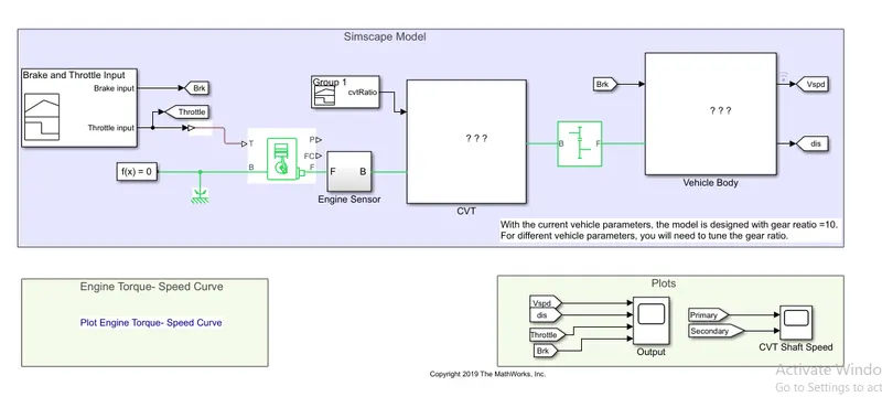
In this model input for throttle & brakes are predefined and CVT gear ratio input through predefined plot & the gear ratio for the vehicle used is 10 & the simulation time is of 200secs.
ATV-MODEL
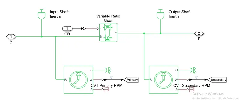
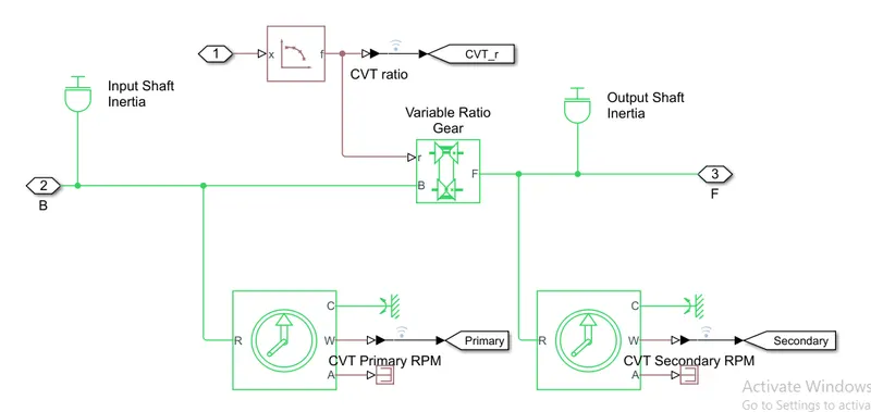
CVT-GEAR-MODEL
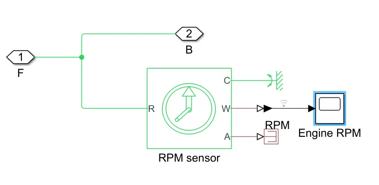
ENGINE SENSOR
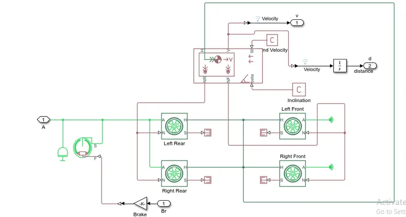
VEHICLE BODY
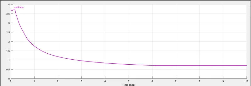
INPUT CVT SIGNAL
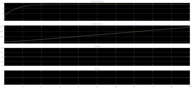
OUTPUT FOR CVT MODEL(VELOCITY, DISTANCE, THROTLE & BRAKE)
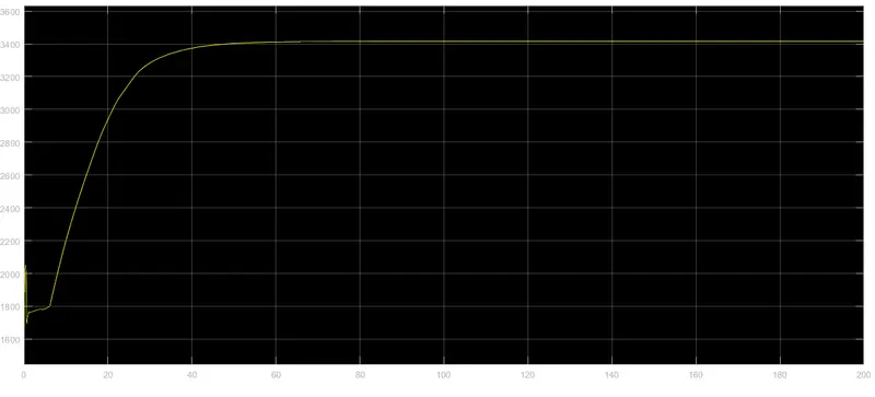
OUTPUT FOR ENGINE RPM
OUTPUT FOR RPM(PRIMARY & SECONDARY RPM)
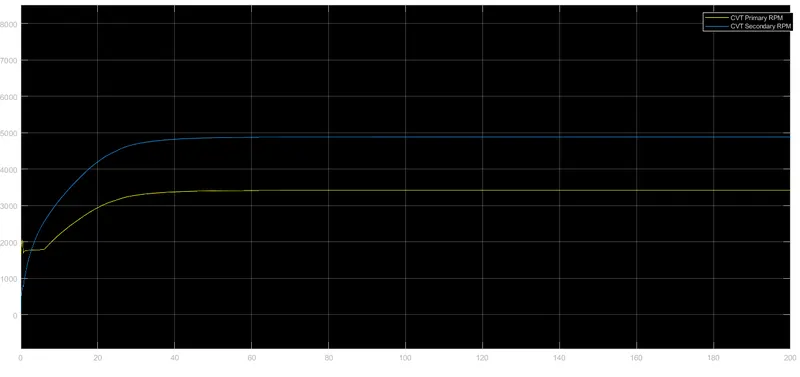
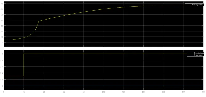
Conclusion:- As we can see that the input for brakes & throttle is constant the velocity is also constant after acheiving its maximum velocity according to the given throttle value, the RPM for engine and the output RPM of the primary (driver) & the secondary (driven) RPM is also constant after acheiving its maximum value.
MODEL-2(ATV-MODEL WITH DASHBOARD)
In this model input was provide as variable input for throttle & brake through the dashboard knob and CVT gear ratio input through predefined plot. The gear ratio of the vehicle is same 10 & the simulation time is inf. (infinity) so that we can change the value of the throttle & brake during simulation.
ATV-MODEL WITH DASHBOARD
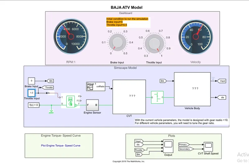
CVT-GEAR-MODEL
ENGINE SENSOR
VEHICLE BODY
INPUT CVT SIGNAL
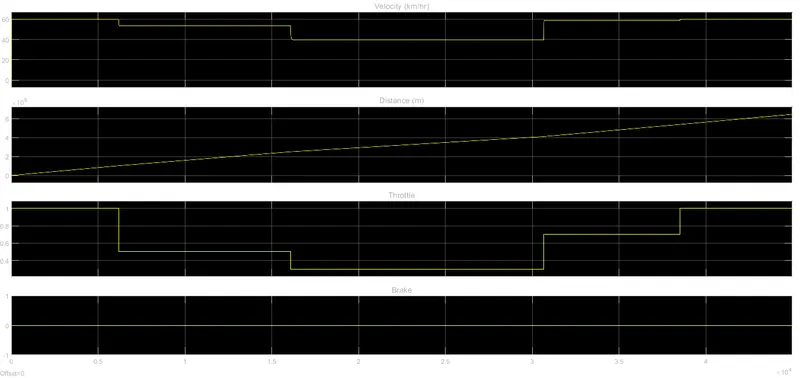
OUTPUT FOR CVT MODEL WITH DASHBOARD(VELOCITY, DISTANCE, THROTLE & BRAKE)
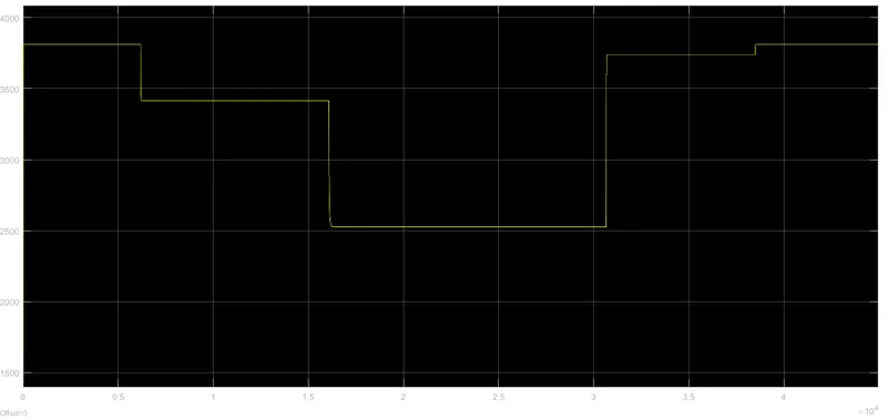
OUTPUT FOR ENGINE RPM
OUTPUT FOR RPM(PRIMARY & SECONDARY RPM)
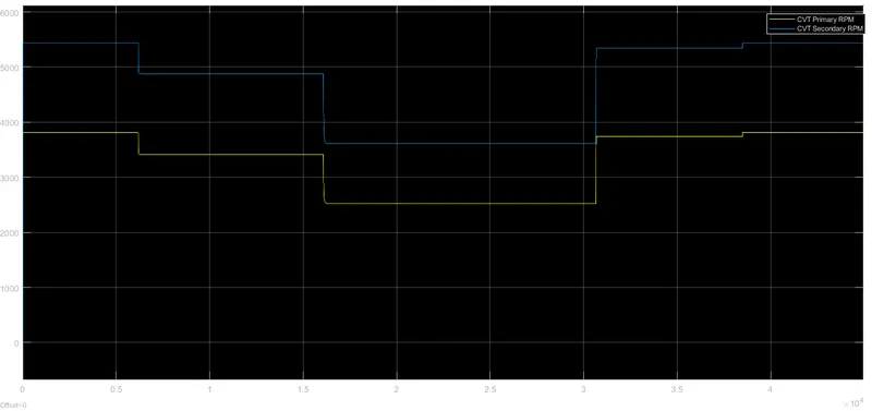
CONCLUSION:- As we can see, that the input for brakes & throttle is varied through the knob, the value of the Velocity changes accordingly, also the engine RPM & the primary & secondary RPM of the model also changes
MODEL-3(ATV MODEL MAPPED INPUT)
In this model the input is same as first model i.e. input for throttle & brakes are predefined and CVT gear ratio input through mapped output of the system is taken as inout for the CVT i.e. through Lookup Table
ATV MODEL MAPPED INPUT
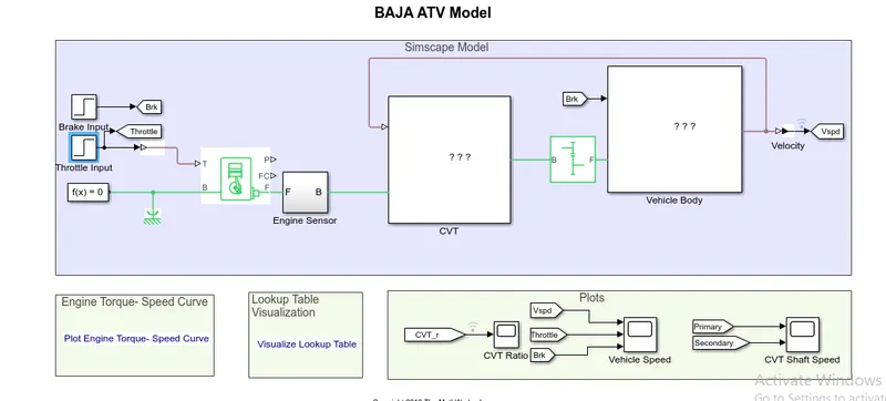
CVT-GEAR MODEL
ENGINE SENSOR
VEHICLE BODY
OUTPUT FOR CVT MODEL MAPPED WITH DASHBOARD(VELOCITY, THROTLE & BRAKE)
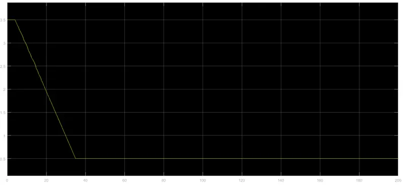
OUTPUT FOR CVT MODEL MAPPED WITH DASHBOARD(CVT Gear Ratio)
OUTPUT FOR ENGINE RPM
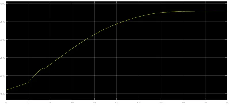
OUTPUT FOR RPM(PRIMARY & SECONDARY RPM)
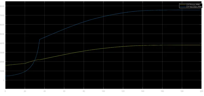
CONCLUSION:- As we can see that, the output here depends on both input i.e. throttle & brake as well as the lookup input of the CVT gear box, so the output for the Velocity, engine RPM & the primary & secondary RPM changes accordingly.
MODEL-4(ATV MODEL MAPPED INPUT WITH DASHBOARD)
In this model the input is same as second model i.e. input was provide as variable input for throttle & brake through the dashboard knob and CVT gear ratio input through mapped output of the system is taken as inout for the CVT i.e. through Lookup Table
ATV MODEL MAPPED INPUT WITH DASHBOARD
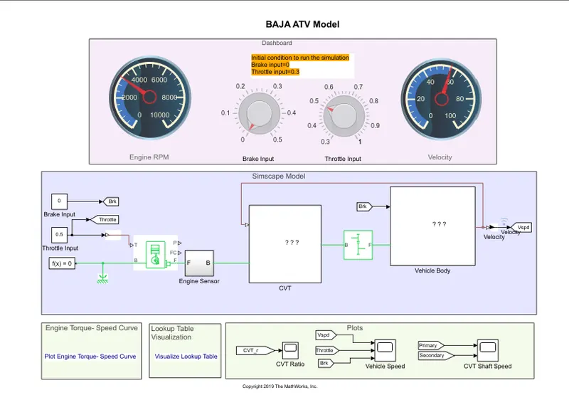
CVT-GEAR MODEL
ENGINE SENSOR
VEHICLE BODY
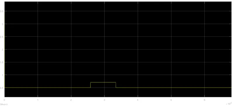
OUTPUT FOR CVT MODEL MAPPED WITH DASHBOARD(VELOCITY, THROTLE & BRAKE)
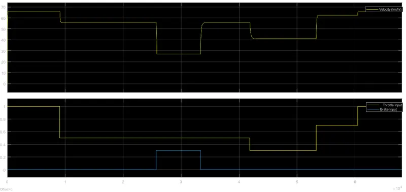
OUTPUT FOR CVT MODEL MAPPED WITH DASHBOARD(CVT Gear Ratio)
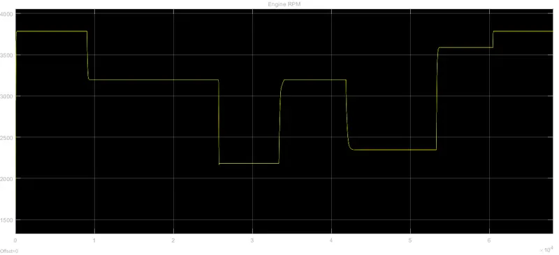
OUTPUT FOR ENGINE RPM
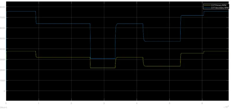
OUTPUT FOR RPM(PRIMARY & SECONDARY RPM)
PLOT FOR ENGINE TORQUE & SPEED
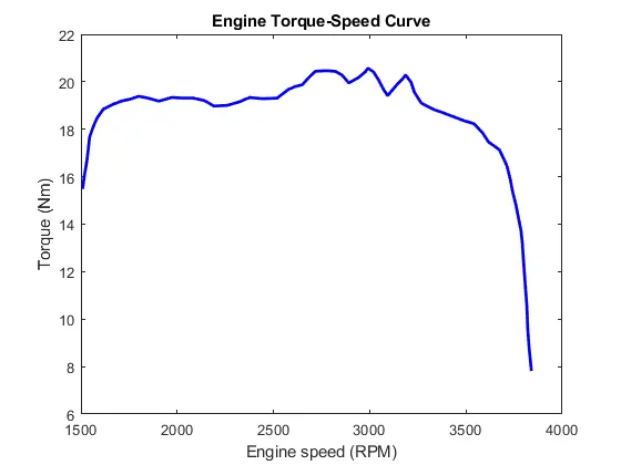
VISUALIZATION OF LOOKUP TABLE.
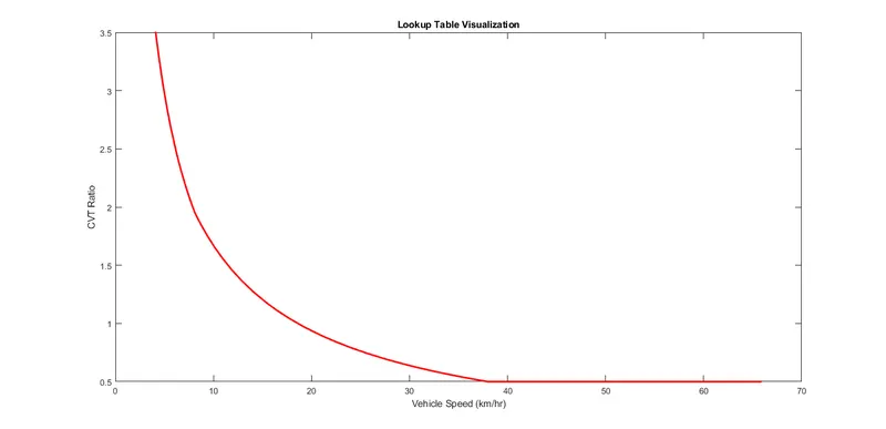
CONCLUSION:- As we can see that, the output here depends on both input i.e. throttle & brake as well as the lookup input of the CVT gear box, so as we change the input for the throttle & brakes through the dashboard knobs the output for the Velocity, engine RPM & the primary & secondary RPM changes accordingly.