Project
AIM: Carry out a system-level simulation of an all-terrain vehicle. Prepare a technical report explaining the model properties & comments on the results.
Theory:
All-terrain Vehicle:
- An all-terrain vehicle (ATV), also known as a light utility vehicle (LUV), a quad bike, or simply a quad, as defined by the American National Standards Institute (ANSI); is a vehicle that travels on low-pressure tires, with a seat that is straddled by the operator, along with handlebars for steering control. As the name implies, it is designed to handle a wider terrain than most other vehicles. Although it is a street-legal vehicle in some countries, it is not street-legal within most states, territories, and provinces of Australia, the United States, or Canada.
- By the current ANSI definition, ATVs are intended for a single operator, although some companies have developed ATVs for the operator and one passenger. These ATVs are referred to as tandem ATVs.
- The rider sits on and operates these vehicles like a motorcycle, but the extra wheels give more stability at slower speeds. Although most are equipped with three or four wheels, six-wheel models exist for specialized applications. Multiple-user analogs with side-by-side seating are called utility terrain vehicles (UTVs) or side-by-sides to distinguish vehicle classes. Both classes tend to have similar powertrain parts. Engine sizes of ATVs currently for sale in the United States (as of 2008 products) range from 49 to 1,000 cc (3.0 to 61 cu in).
Baja SAE:
- The Baja SAE Competition originated at the University of South Carolina in 1976, under the supervision of Dr. Harit Mehta. Only ten teams took part in the very first race. Since that time, the competition has grown to become a premier engineering design series, with over 110 university teams participating in each race.
- The goal in Baja SAE racing is to design, build and race off-road vehicles that can withstand the harshest elements of rough terrain. The vehicles used in Baja SAE racing are often similar to dune buggies. Before 2007, the events were called "Mini Baja."
- Each year as many as 141 Baja cars are entered in the Baja SAE events across the US and worldwide. International events are endorsed by SAE International and are held in Brazil, Korea, South Africa, and México.
- All cars must adhere to SAE International's rules and pass SAE's technical inspection and judging; a car may not race until all safety inspections are passed. Small engine manufacturer Briggs & Stratton sponsors Baja SAE teams by providing the SAE sanctioned engine free of charge, at a replacement rate of one engine for every two years in competition.
- There are multiple dynamic events photographed by Official SAE Photographer Jethro Gaines of J. Gaines Studio, usually four per event and a single four-hour endurance race. The dynamic events include hill climbs, sled pulls, maneuverability events, rock crawls, and suspension & traction events. Previously the cars had to float and propel themselves on the water under their own power. This was changed from the 2012 competitions onward due to safety concerns.
- Static events, such as written reports, presentations, and design evaluations, are provided by participating teams. This is when the teams are judged on their cars' ergonomics, functionality, and producibility, ensuring that the team's final placement does not rest solely on the vehicle's performance but rather on a combination of static and dynamic events. Required reports detail the engineering and design process used to develop each team's vehicle system, supported with sound engineering principles.
- Also, a cost report that provides all the background information necessary to verify the vehicle's actual cost is used to rate the most economically feasible production. These reports are submitted weeks in advance of each event, where the presentations and design evaluations are given on-site in the presence of SAE design judges. Teams with noticeable differences between the car and the cost report can be audited. If the report and car do not match, the team will be served penalty points.
- Starting in 2022, all cars will be required to utilize a 4WD drive train system. Top teams have locked into a standard design in recent years, so the new drive train requirements serve as an opportunity for students to design systems from the ground up and shake up the design possibilities.
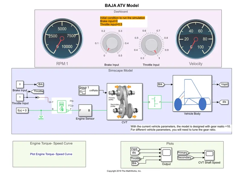
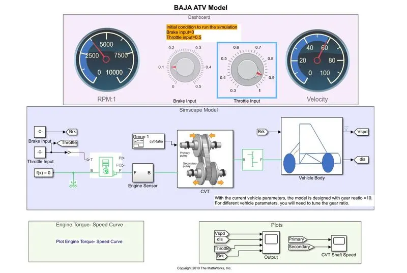
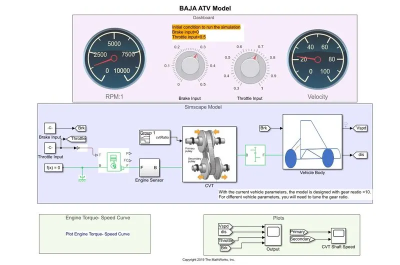
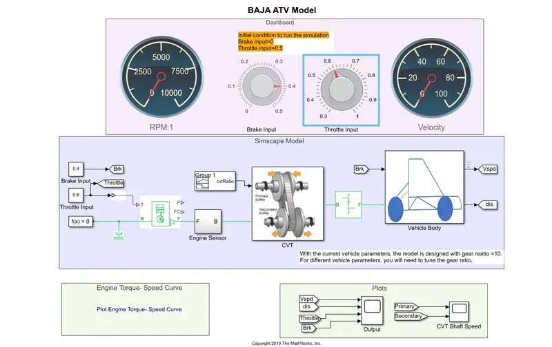
The Simulink Block Diagram of All-Terrain Vehicle Model:
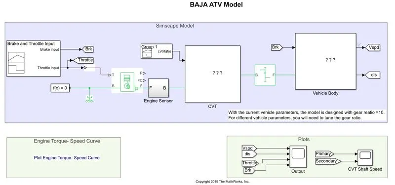
The Blocks used to create the BAJA ATV Model are:
-
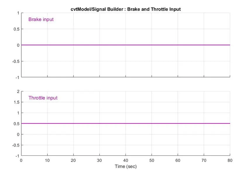
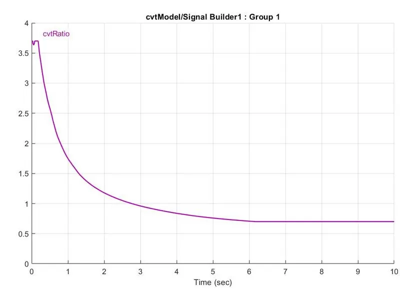
Signal Builder - The Signal Builder block allows you to create interchangeable groups of piecewise linear signal sources and use them in a model.
-
Goto - The Goto block passes its input to its corresponding From blocks. The input can be a real- or complex-valued signal or vector of any data type. From and Goto blocks allow you to pass a signal from one block to another without connecting them.
-
Simulink PS Converter - Converts the Simulink input signal to a Physical Signal.
-
Generic Engine - Represents a system-level model of spark-ignition and diesel engines suitable for use at the initial modeling stages when only the basic parameters are available.
-
Solver Configuration - The Solver Configuration block specifies the solver parameters that your model needs before you can begin the simulation.
-
Mechanical Rotational Reference - The Mechanical Rotational Reference block represents a reference point, or frame, for all mechanical rotational ports.
-
Engine Sensor - It's a Subsystem model consisting of the following simulation blocks & their purpose are as follows:
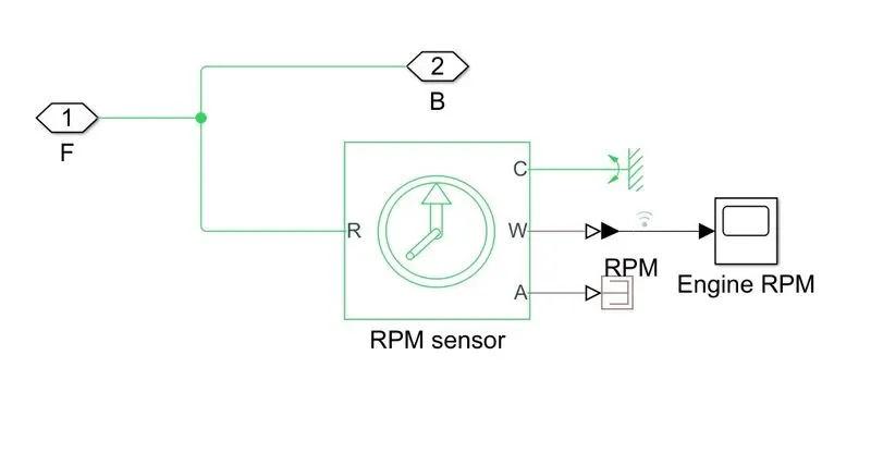
- Ideal Rotational Motion Sensor - The Ideal Rotational Motion Sensor block represents an ideal mechanical rotational motion sensor, a device that converts an across variable measured between two mechanical rotational nodes into a control signal proportional to angular velocity or angle.
- Mechanical rotational Reference - The Mechanical Rotational Reference block represents a reference point, or frame, for all mechanical rotational ports.
- PS-Simulink Converter - Converts the input Physical Signal to a Simulink output signal.
- Scope - Display signals generated during simulation.
- PS terminator - Use this block to terminate physical signal outputs.
- CVT - It's a Subsystem model consisting of the following simulation blocks & their purpose are as follow:
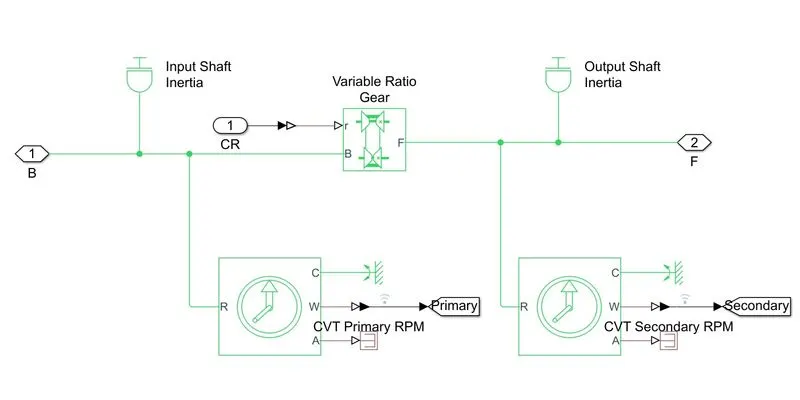
- Inertia - The block represents an ideal mechanical rotational inertia.
-
Ideal Rotational Motion Sensor - The Ideal Rotational Motion Sensor block represents an idealmechanical rotational motion sensor, that is, a device that converts an across variable measuredbetween two mechanical rotational nodes into a control signal proportional to angular velocity orangle.
-
Mechanical rotational Reference - The Mechanical Rotational Reference block represents a reference point, or frame, for all mechanical rotational ports.
-
PS-Simulink Converter - Converts the input Physical Signal to a Simulink output signal.
-
Goto - The Goto block passes its input to its corresponding From blocks. The input can be areal- or complex-valued signal or vector of any data type. From and Goto blocks allow you to passa signal from one block to another without connecting them.
-
PS terminator - Use this block to terminate physical signal outputs.
-
Variable Ratio Transmission - Represents a variable ratio gearbox implemented by mechanical belt CVT, electric, or hydraulic transmissions.
-
Simple Gear - Represents a fixed-ratio gear or gearbox.
-
Vehicle Body - CVT - It's a Subsystem model consisting of the following simulation blocks & their purpose are as follows:
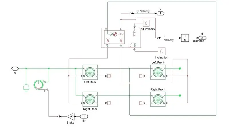
- Inertia - The block represents an ideal mechanical rotational inertia.
- PS-Simulink Converter - Converts the input Physical Signal to a Simulink output signal.
- PS terminator - Use this block to terminate physical signal outputs.
-
Double Shoe Brake - Represents a brake arranged as two pivoted rigid shoes symmetrically installed inside or outside a drum and operated by one actuator. The actuator force causes the shoes to exert friction torque on a shaft connected to the drum.
-
Gain - Element-wise gain (y = K.*u) or matrix gain (y= K*uory=u*K).
-
Tyre - Represents the longitudinal behavior of a highway tire characterized by the tire Magic.Formula.
-
Vehicle Body - Represents a two-axle vehicle body in longitudinal motion. Due to acceleration and road profile, the block accounts for body mass, aerodynamic drag, road incline, and weight distribution between axles.
-
PS Constant - This block creates a physical signal constantly.
-
Integrator - The Integrator block outputs the value of the integral of its input signal concerning the time.
- From - Receive signals from the Goto block with the specified tag. If the tag is defined as 'scoped' in the Goto block, then a Goto Tag Visibility block must be used to define the visibility of the tag. After 'Update Diagram,' the block icon displays the selected tag name (local tags are enclosed in brackets, [], and scoped tag names are enclosed in braces, {}).
- Scope - Display signals generated during simulation.
RESULTS:
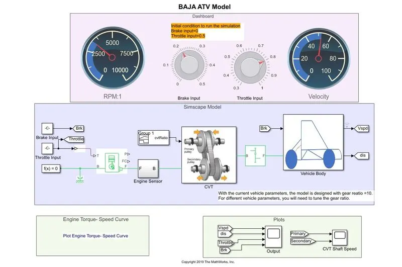
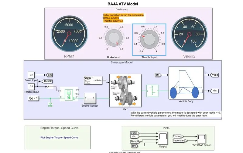
The Simulink Block Diagram of All-Terrain Vehicle Model - cvtModel:
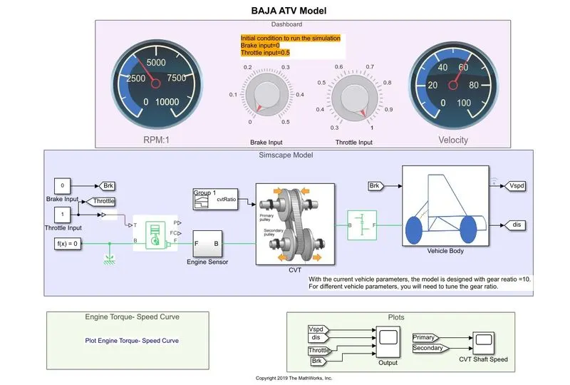
The Blocks used to create the BAJA All-Terrain Vehicle Model - cvtModel:
-
Signal Builder - The Signal Builder block allows you to create interchangeable groups of piecewise linear signal sources and use them in a model.
- Circular Gauge - Display an input value on a customized gauge.
- Knob - Set a value to tune parameters or variables.
-
Goto - The Goto block passes its input to its corresponding From blocks. The input can be a real- or complex-valued signal or vector of any data type. From and Goto blocks allow you to pass a signal from one block to another without connecting them.
-
Simulink PS Converter - Converts the Simulink input signal to a Physical Signal.
-
Generic Engine - Represents a system-level model of spark-ignition and diesel engines suitable for use at the initial modeling stages when only the basic parameters are available.
-
Solver Configuration - The Solver Configuration block specifies the solver parameters that your model needs before you can begin the simulation.
-
Mechanical Rotational Reference - The Mechanical Rotational Reference block represents a reference point, or frame, for all mechanical rotational ports.
- Constant - Output the constant specified by the constant value block.
-
Engine Sensor - It's a Subsystem model consisting of the following simulation blocks & their purpose are as follows:
- Ideal Rotational Motion Sensor - The Ideal Rotational Motion Sensor block represents an ideal mechanical rotational motion sensor, a device that converts an across variable measured between two mechanical rotational nodes into a control signal proportional to angular velocity or angle.
- Mechanical rotational Reference - The Mechanical Rotational Reference block represents a reference point, or frame, for all mechanical rotational ports.
- PS-Simulink Converter - Converts the input Physical Signal to a Simulink output signal.
- Scope - Display signals generated during simulation.
- PS terminator - Use this block to terminate physical signal outputs.
- CVT - It's a Subsystem model consisting of the following simulation blocks & their purpose are as follow:
- Inertia - The block represents an ideal mechanical rotational inertia.
-
Ideal Rotational Motion Sensor - The Ideal Rotational Motion Sensor block represents an idealmechanical rotational motion sensor, that is, a device that converts an across variable measuredbetween two mechanical rotational nodes into a control signal proportional to angular velocity orangle.
-
Mechanical rotational Reference - The Mechanical Rotational Reference block represents a reference point, or frame, for all mechanical rotational ports.
-
PS-Simulink Converter - Converts the input Physical Signal to a Simulink output signal.
-
Goto - The Goto block passes its input to its corresponding From blocks. The input can be areal- or complex-valued signal or vector of any data type. From and Goto blocks allow you to passa signal from one block to another without connecting them.
-
PS terminator - Use this block to terminate physical signal outputs.
-
Variable Ratio Transmission - Represents a variable ratio gearbox implemented by mechanical belt CVT, electric, or hydraulic transmissions.
-
Simple Gear - Represents a fixed-ratio gear or gearbox.
-
Vehicle Body - CVT - It's a Subsystem model consisting of the following simulation blocks & their purpose are as follows:
- Inertial - The block represents an ideal mechanical rotational inertia.
- PS-Simulink Converter - Converts the input Physical Signal to a Simulink output signal.
- PS terminator - Use this block to terminate physical signal outputs.
-
Double Shoe Brake - Represents a brake arranged as two pivoted rigid shoes symmetrically installed inside or outside a drum and operated by one actuator. The actuator force causes the shoes to exert friction torque on a shaft connected to the drum.
-
Gain - Element-wise gain (y = K.*u) or matrix gain (y= K*uory=u*K).
-
Tyre - Represents the longitudinal behavior of a highway tire characterized by the tire Magic.Formula.
-
Vehicle Body - Represents a two-axle vehicle body in longitudinal motion. Due to acceleration and road profile, the block accounts for body mass, aerodynamic drag, road incline, and weight distribution between axles.
-
PS Constant - This block creates a physical signal constantly.
-
Integrator - The Integrator block outputs the value of the integral of its input signal concerning the time.
- From - Receive signals from the Goto block with the specified tag. If the tag is defined as 'scoped' in the Goto block, then a Goto Tag Visibility block must be used to define the visibility of the tag. After 'Update Diagram,' the block icon displays the selected tag name (local tags are enclosed in brackets, [], and scoped tag names are enclosed in braces, {}).
- Scope - Display signals generated during simulation.
RESULTS:
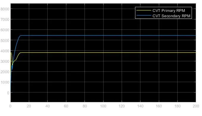
Brake Input = 0 Throttle Input = 1:
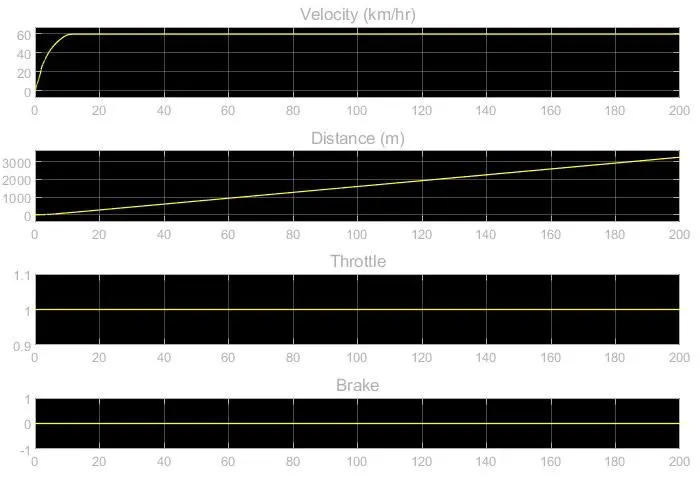
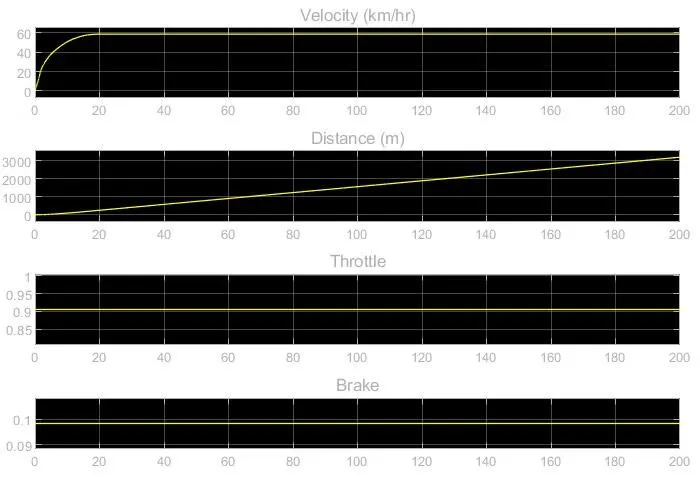
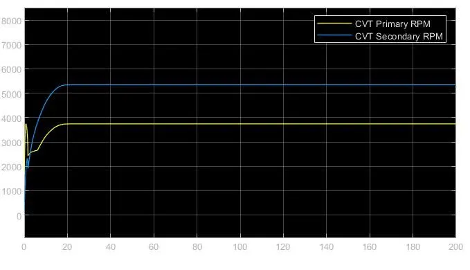
Brake Input = 0.1 Throttle Input = 0.9:
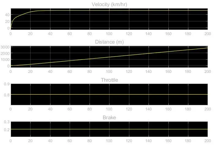
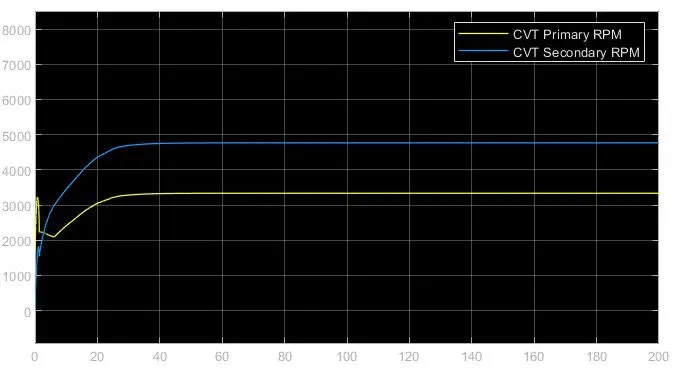
Brake Input = 0.2 Throttle Input = 0.8:
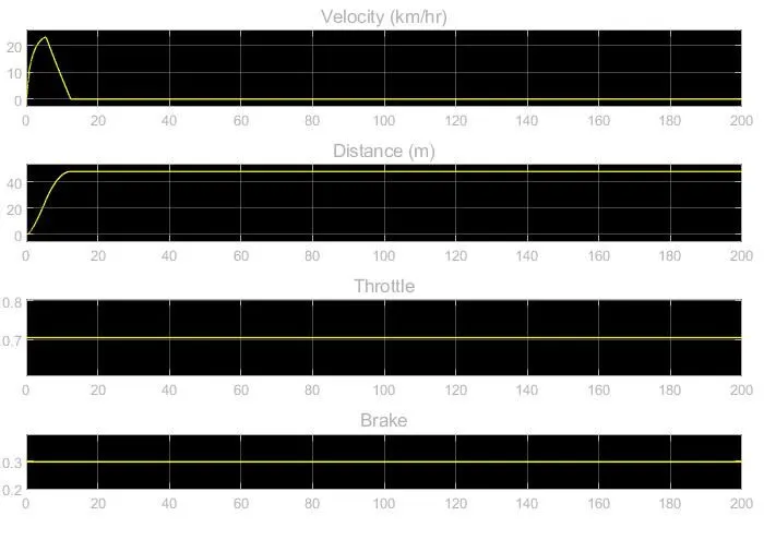
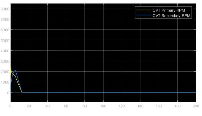
Brake Input = 0.3 Throttle Input = 0.7:
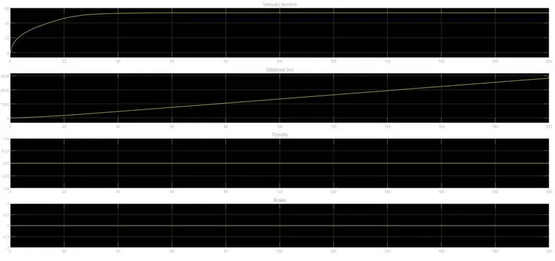
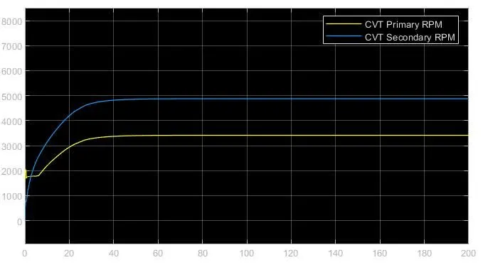
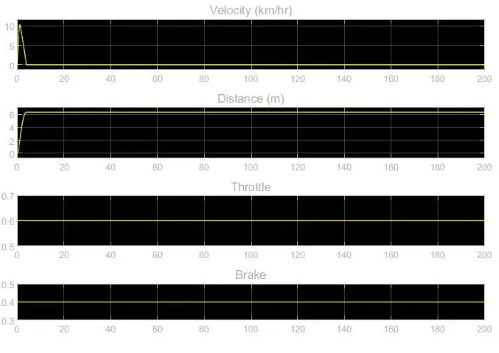
Brake Input = 0.4 Throttle Input = 0.6:
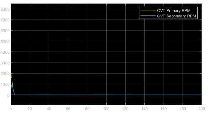
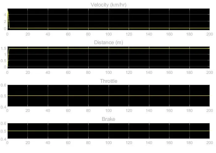
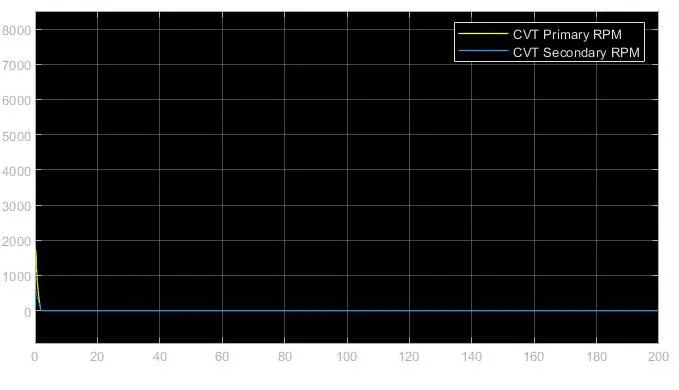
Brake Input = 0.5 Throttle Input = 0.5:
Conclusions:
- From this model, we get to understand how the All-Terrain Vehicle works under the provided conditions.
- Calculated the time required to accelerate to a certain speed or to decelerate to a certain speed.
- Calculated the max speed achieved by the All-Terrain Vehicle.
- Observed the throttle input and the performance of the brakes.