Project
What is GD&T?
GD&T, short for Geometric Dimensioning and Tolerancing, is a system for defining and communicating design intent and engineering tolerances that help engineers and manufacturers optimally control variations in manufacturing processes.
Limitations of Tolerancing Before GD&T
Before GD&T, manufacturing features were specified by X-Y areas. For example, when drilling a mounting hole, the hole had to be within a specified X-Y area.
An accurate tolerancing specification, however, would define the position of the hole about the intended position, the accepted area being a circle. X-Y tolerancing leaves a zone in which inspection would have produced a false negative because while the hole is not within the X-Y square, it would fall within the circumscribed circle.
Stanley Parker, an engineer who was developing naval weapons during World War II, noticed this failure in 1940. Driven by the need for cost-effective manufacturing and meeting deadlines, he worked out a new system through several publications. Once proven as a better operational method, the new system became a military standard in the 1950s.
Currently, the GD&T standard is defined by the American Society of Mechanical Engineers (ASME Y14.5-2018) for the USA and ISO 1101-2017 for the rest of the world. It concerns mostly the overall geometry of the product, while other standards describe specific features such as surface roughness, texture, and screw threads.
How GD&T Works
Engineering drawings need to show the dimensions for all features of a part. Next to the dimensions, a tolerance value needs to be specified with the minimum and maximum acceptable limit. The tolerance is the difference between the minimum and maximum limits. For example, if we have a table that we would accept with a height between 750 mm and 780 mm, the tolerance would be 30 mm.
However, the tolerance for the table implies that we would accept a table that is 750 mm high on one side and 780 mm on the other or has a waved surface with a 30 mm variation. So to appropriately tolerate the product, we need a symbol communicating the design intent of a flat top surface. Therefore we have to include an additional flatness tolerance in addition to the overall height tolerance.
Similarly, a cylinder with a toleranced diameter will not necessarily fit into its hole if the cylinder gets slightly bent during the manufacturing process. Therefore it also needs a straightness control, which would be difficult to communicate with traditional plus-minus tolerancing. Or a tube that has to match a complex surface that it’s welded to seamlessly requires a surface profile control.
GD&T establishes a library of symbols to convey such design intents, which we discuss in the following section.
The art of tolerancing means specifying just the right variations for all specific design features to maximize product approval rate within the limits of the manufacturing processes and depending on the part’s visual and functional purpose.
In the metric system, there are International Tolerance (IT) grades that can also be used to specify tolerances using symbols. The symbol 40H11, for example, means a 40 mm diameter hole with a loose running fit. The manufacturer only needs to look up the basis table for hole features to derive the exact tolerance value.
Besides individual tolerances, engineers must take into account system-level effects. For example, when a part comes out with all dimensions at their maximum allowed value, does it still meet overall requirements such as product weight and wall thicknesses? This is called the Maximum Material Condition (MMC), while its counterpart is the Least Material Condition (LMC).
Tolerances also stack up. If we create a chain link where each hole has a 0.1 mm plus tolerance and each shaft has a 0.1 mm negative tolerance, that means we will still accept a 20 mm length difference at 100 links. When installing repeated elements such as a perforated hole pattern, first position the pattern and then specify interrelated distances rather than referencing elements to a fixed edge or plane of the part.
The standards do not only pertain to designers and engineers but also quality inspectors by informing them how to measure the dimensions and tolerances. Using specific tools such as digital micrometers and calipers, height gauges, surface plates, dial indicators, and a coordinate measuring machine (CMM) are important to tolerancing practice.
When measuring and defining a part, the geometry exists in a conceptual space called the Datum Reference Frame (DRF). This is comparable to the coordinate system at the origin of space in 3D modeling programs. A datum is a point, line, or plane that exists in the DRF and is used as a starting place for measuring. Make sure to define the datum features relevant to the functionality of your part. Unless you are mating features of one part to those of others in an assembly, you can often use a single datum. Always ensure that the primary datum has a reliable location to derive other measurements from, for example, where the final part will have little unpredictable variation.
GD&T Tolerancing Guidelines
An engineering drawing has to accurately convey the product without adding unnecessary complexity or restrictions. The following guidelines are helpful to consider:
-
The clarity of a drawing is the most important, even more so than its accuracy and completeness. To improve clarity, draw dimensions and tolerances outside of the part's boundaries and applied to visible lines in true profiles, employ a unidirectional reading direction, convey the function of the part, group and/or stagger dimensions, and make use of white space.
-
Always design for the loosest feasible tolerance to keep costs down.
-
Use a general tolerance defined at the bottom of the drawing for all dimensions of the part. Specific tighter or looser tolerances indicated in the drawing will then supersede the general tolerance.
-
Tolerance of functional features and their interrelations first, then move on to the rest of the part.
-
Whenever possible, leave GD&T work to the manufacturing experts and do not describe manufacturing processes in the engineering drawing.
-
Do not specify a 90-degree angle since it is assumed.
-
Dimensions and tolerances are valid at 20 °C / 101.3 kPa unless stated otherwise.
GD&T Symbols
GD&T is feature-based, with each feature specified by different controls. GD&T symbols fall into five groups:
-
Form controls specify the shape of features, including:
-
Straightness is divided into line element straightness and axis straightness.
-
Flatness means straightness in multiple dimensions, measured between the highest and lowest points on a surface.
-
Circularity or roundness can be described as straightness bent into a circle.
-
Cylindricity is flatness bent into a barrel. It includes straightness, roundness, and taper, which makes it expensive to inspect.
-
-
Profile controls describe the three-dimensional tolerance zone around a surface:
-
Line Profile compares a two-dimensional cross-section to an ideal shape. The tolerance zone is defined by two offset curves unless otherwise specified.
-
The surface Profile creates two offset surfaces between which the feature surface must fall. This is a complex control typically measured with a CMM.
-
-
Orientation controls concern dimensions that vary at angles, including:
-
Angularity is flatness at an angle to a datum and is also determined through two reference planes spaced the tolerance value apart.
-
Perpendicularity means flatness at 90 degrees to a datum. It specifies two perfect planes the feature plane must lie in between.
-
Parallelism means straightness at a distance. Parallelism for axes can be defined by defining a cylindrical tolerance zone by placing a diameter symbol in front of the tolerance value.
-
-
Location controls define feature locations using linear dimensions:
-
The position is the location of features relative to one another or datums and is the most used control.
-
Concentricity compares the location of a feature axis to the datum axis.
-
Symmetry ensures that non-cylindrical parts are similar across a datum plane. This is a complex control typically measured with a CMM.
-
-
Runout controls define the amount by which a particular feature can vary concerning the datums:
-
Circular Runout is used when there is a need to account for many different errors, such as ball-bearing mounted parts. During inspection, the part is rotated on a spindle to measure the variation or ‘wobble’ around the rotational axis.
-
Total Runout is measured on multiple points of a surface, not just describing the runout of a circular feature but of an entire surface. This controls straightness, profile, angularity, and other variations.
-
GD&T Symbols Overview
Feature Control Frame (FCF)
The Feature Control Frame is the notation to add controls to the drawing. The leftmost compartment contains the geometric characteristic. In the example above, it is a location control but it can contain any of the control symbols. The first symbol in the second compartment indicates the shape of the tolerance zone. In this example, it is a diameter as opposed to a linear dimension. The number indicates the allowed tolerance.
Next to the tolerance box, there are separate boxes for each datum feature that the control refers to. Here, the location will be measured related to datums B and C. Next to the tolerance or a datum feature is an optional encircled letter, the feature modifier.
The following possibilities can occur:
-
M means that the tolerance applies in the Maximum Material Condition (MMC)
-
L means that the tolerance applies in the Least Material Condition (LMC)
-
U indicates an unequal bilateral tolerance, i.e. for a 1 mm tolerance it may specify it as minus 0.20 and 0.80.
-
P means that the tolerance is measured in a Projected Tolerance Zone at a specified distance from the datum.
-
No symbol installs the tolerance regardless of feature size (RFS)
For this example, if the part is not in MMC, a bonus tolerance can be added proportionally to the deviation from MMC. So if a part is at 90% MMC, the tolerance will also loosen by 10%.
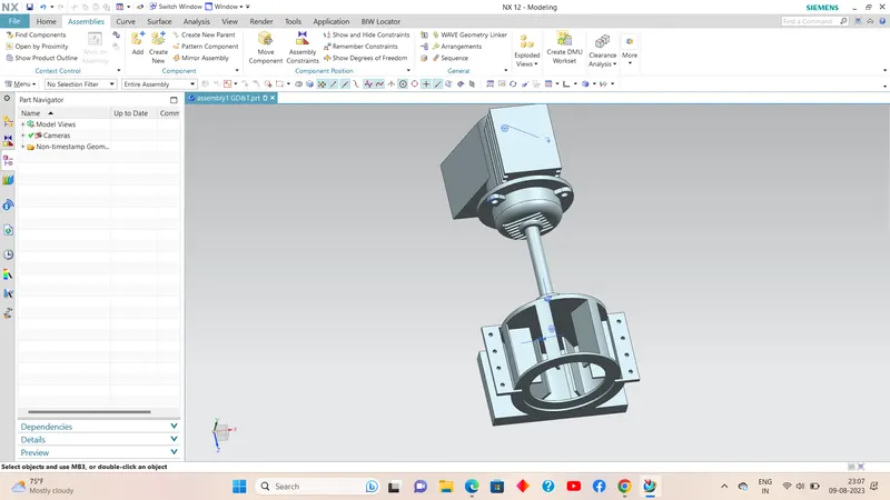
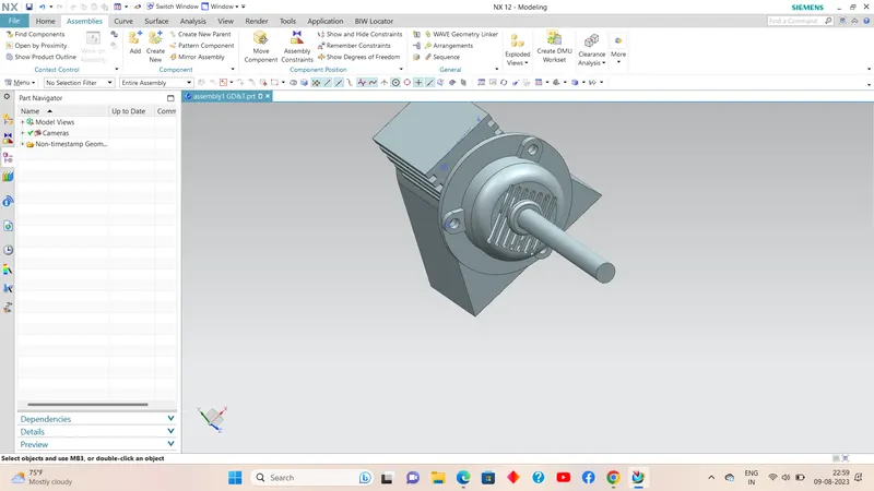
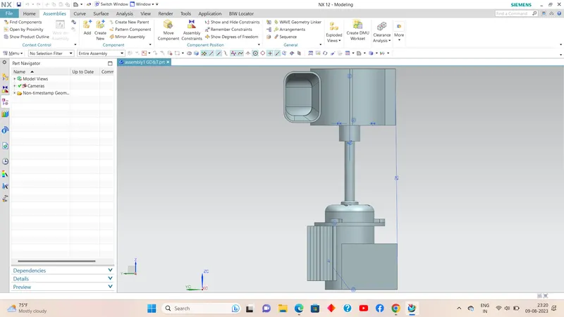
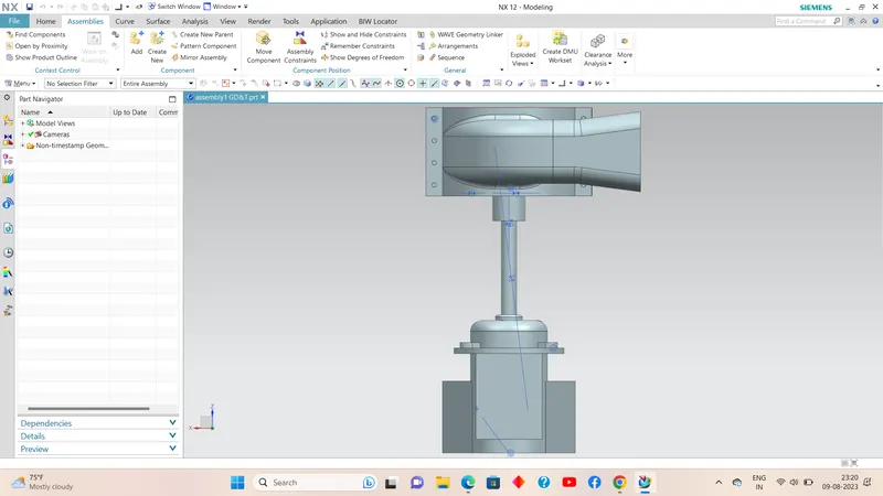
MOTOR BLOWER ASSEMBLY:
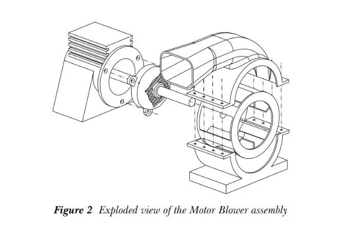
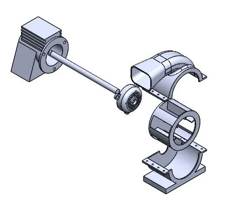
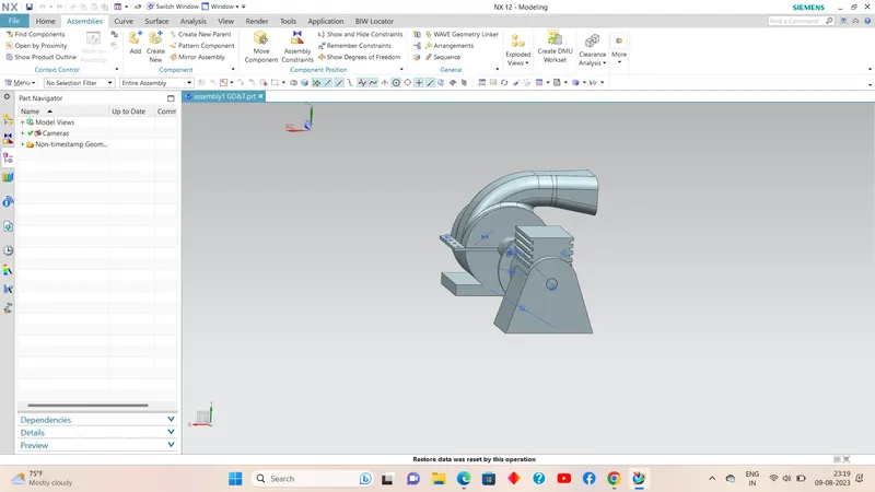
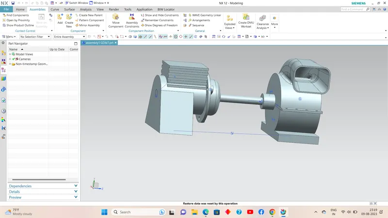
The Motor blower assembly consists of 6 Parts which are first created as part files and later on assembled in an assembly file using different constraints.
EXTRUDE;
EDGE BLEND;
REVOLVE;
SHELL;
PATTERN FEATURE;
BOOLEAN OPERATIONS;
None: It is used for creating a body.
Unite: It is used for adding volume to a solid body.
Subtract: It is used for subtracting volume from the body.
Intersect: It is used for creating volume on the intersection of extruded volume and solid body.
Inferred: It decides which method (none, add, extract, intersect) will use automatically due to drawing.
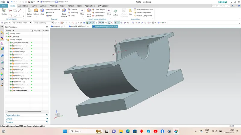
LOWER HOUSING: This part is created by using extrude, pattern geometry, like, etc commands as per the given dimensions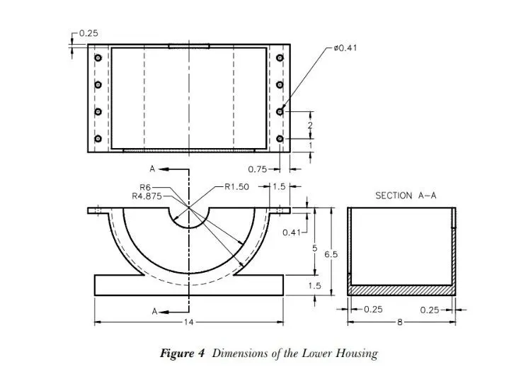
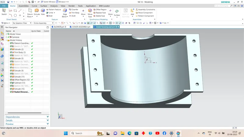
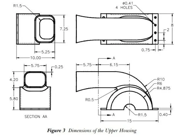
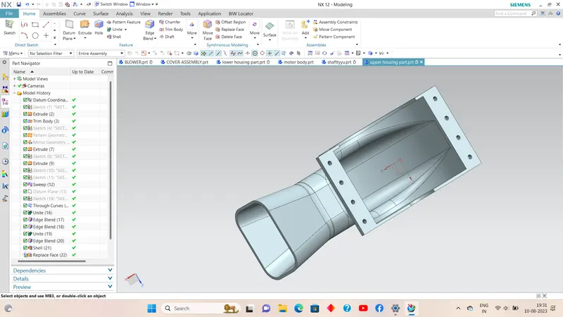
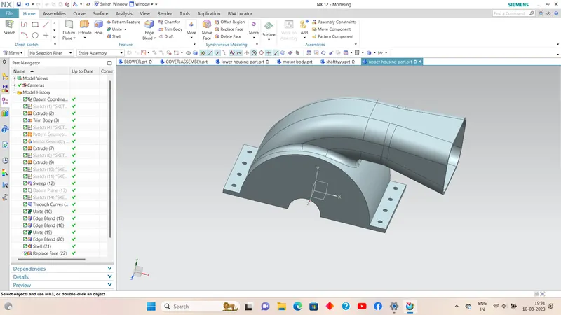
UPPER HOUSING: This part is created by using extrude, sweep, through curves, edge blend, shell, radial dimensions, etc commands as per required and specified dimensions.
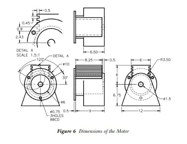
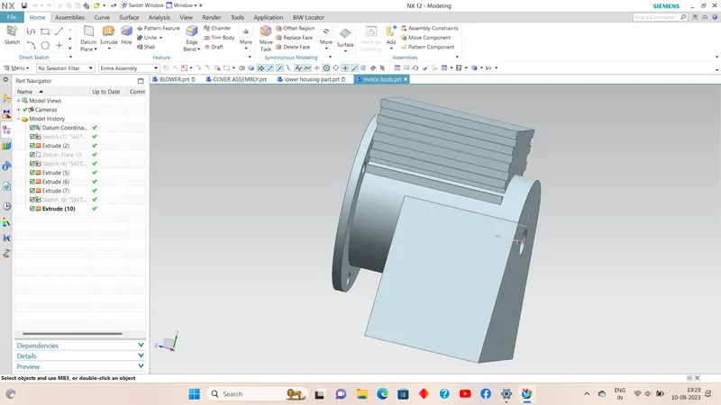
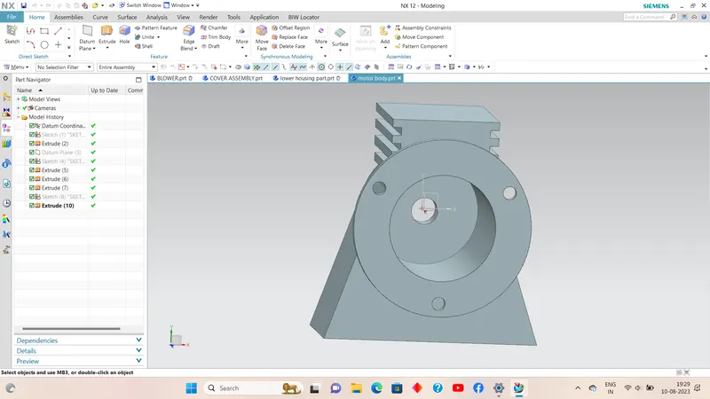
MOTOR:
The motor was created using features like Extrude, by using datum planes at specified distances.
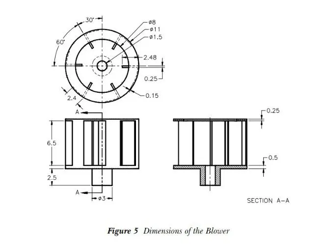
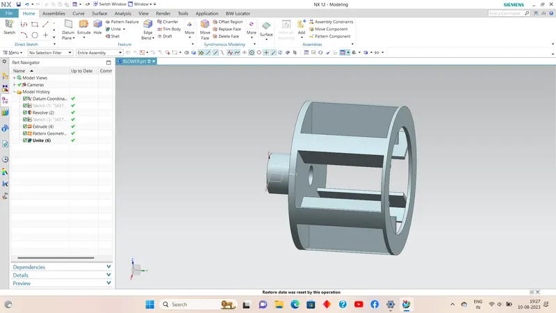
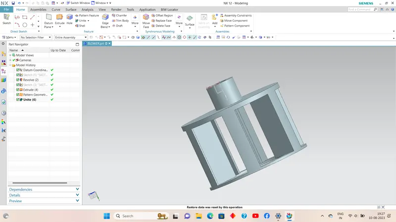
BLOWER:
The blower was created using features like revolve, extrude, and pattern geometry, as per the required dimensions.
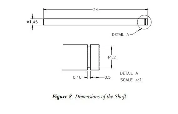
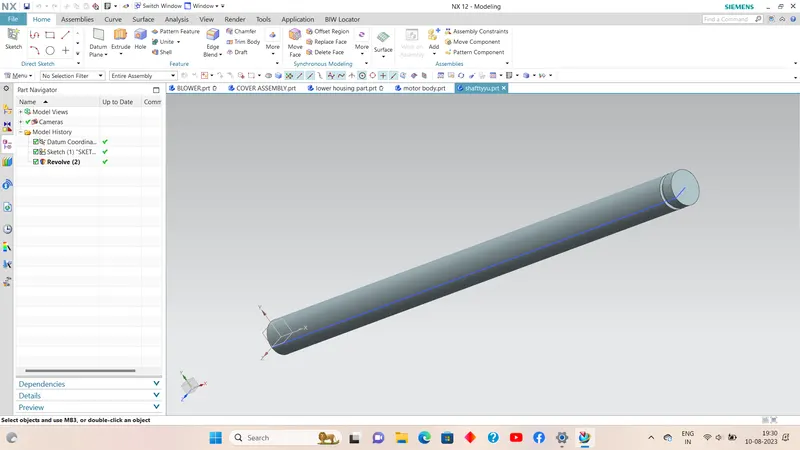
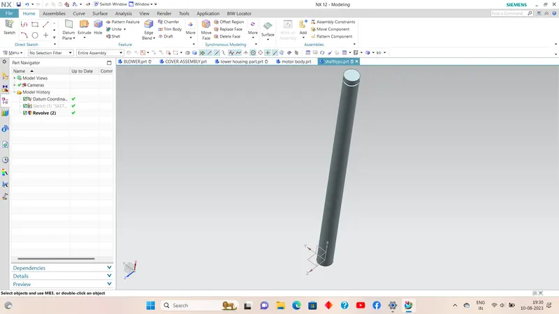
SHAFT:
The shaft was created using the revolve command feature.
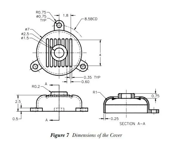
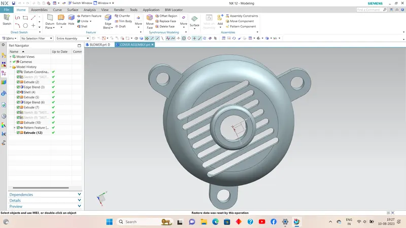
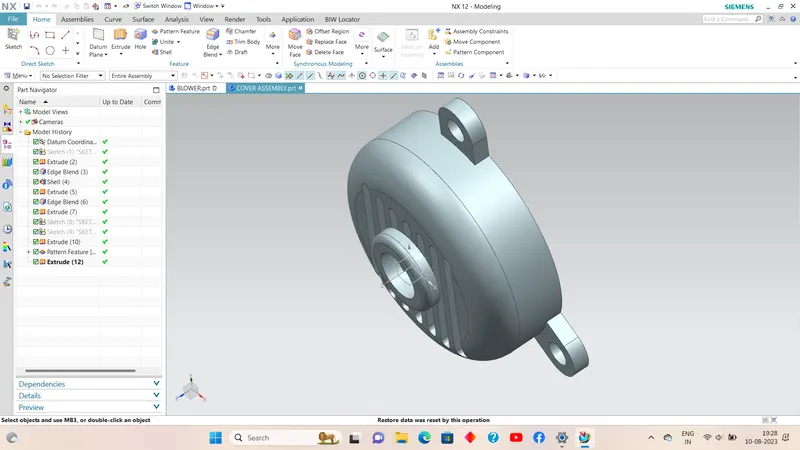
MOTOR COVER: This part is created by using commands like extrude, edge blend, shell, and pattern feature.
ASSEMBLY:
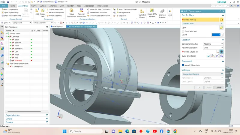
After creating all the different part files they are assembled in an assembly file by using different constraints.
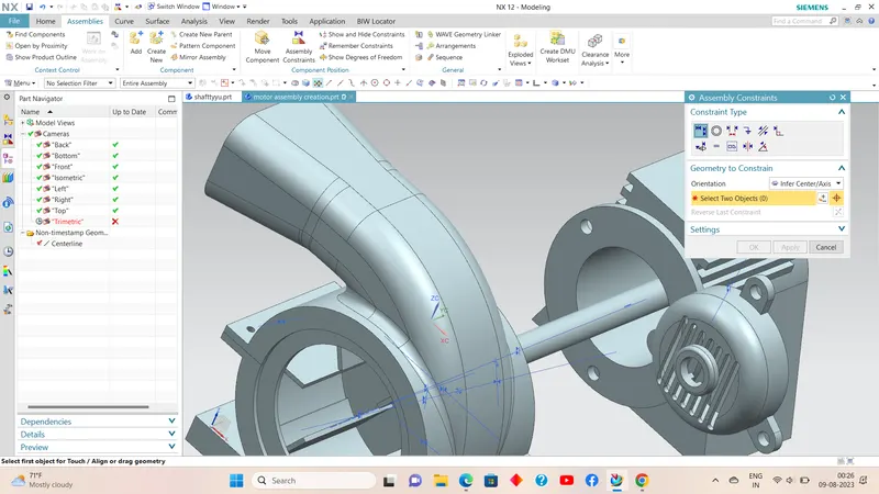
assembly Constraints define relations between components in the assembly.
You can activate the “Assembly Constraints“ command by:
– Select the “Assembly Constraints“ command from “Menu=>Assemblies=>Component Position=> Assembly Constraints”
– Click on the “Assembly Constraints“ command on Home Ribbon Bar.
– Click on the “Assembly Constraints“ command on the Assemblies Ribbon Bar.
You can freely move or rotate objects on the screen when the “Assembly Constraints” command is activated due to its constraints.
- To move the component: activate the “Assembly Constraints“ command then press and hold the left mouse button on the component then drag the mouse on the screen
- To rotate the component: activate the “Assembly Constraints“ command then press and hold “alt” on the keyboard, then press and hold the left mouse button on the component and drag the mouse on the screen
Assembly Constraints pop up window:
- Constraint type: You can select constraint types. Also, you can deactivate constraints from the “Enabled constraint” tabs in settings.
- Touch Align planar or straight surfaces/edges/planes/centerlines touch or align.
- Concentric: constraints components through circular edges.
- Distance: specifies the distance between components' surfaces or edges.
- Fix: fixes component on its current position
- Parallel: defines parallel surfaces/edges/planes etc… between components.
- Perpendicular: defines perpendicularity between surfaces/edges/planes etc… between components.
- Align/Lock: Same as concentric but components can’t rotate around defined constraints.
- Fit: constrains cylindrical surfaces that have the same radius.
- Bond: defines the bond between selected components. Bonded components move together in assembly.
- Center: centers components through selected objects. (Surfaces, planes, axis, edges, etc…)
- Angle: defines the angle between components surfaces, edges, etc…
- Geometry to constrain: It is used to define constraint objects. It will be active after the command started. Options changes due to the selected constraint type.
You can change the direction of the constraint by clicking the icon near the reverse last constraint. - Settings: You can change settings for the Assembly Constraints.