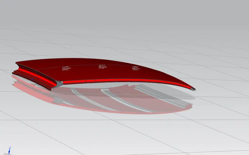
Project 3: Roof Modeling
Aim:- To design roof of vehicle and its components like roof rails and bow roofs. Also to validate design with with two techniques and perform draft analysis for manufacturing feasibility.
Introduction:- Roof is upper portion of vehicle. Basically it protects the vehicle. So, it's design must satisfy some criteria to meet strength requirement. As it visible, it is major styling part of vehicle. It may accomodate styling and functional elements line sunroof and antennas. In roll-over condition, roof of vehicle performs important role. So a static test is done to demonstrate roll-over condition. In which static load is applied over roof in specific angles. So bow roofs are placed at various locations to strengthen the roof. We may give embossing to roof for more strength.
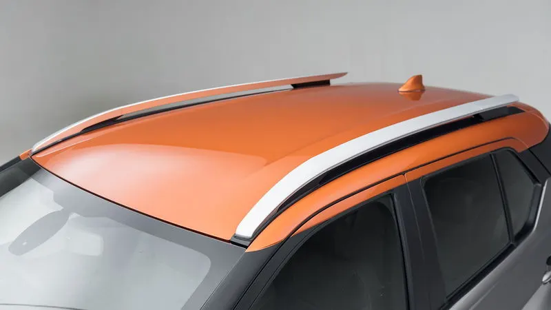
Design procedure:- There are 4 components other than roof required for strengthen the roof. The whole roof structure is designed in following way:-
Side flanges:- Roof side flanges runs peripheral to the roof edges. They are meant for the strength and to attached roof to other BIW components. It is easy to design flanges to the roof. In foolowing way flanges are design:-
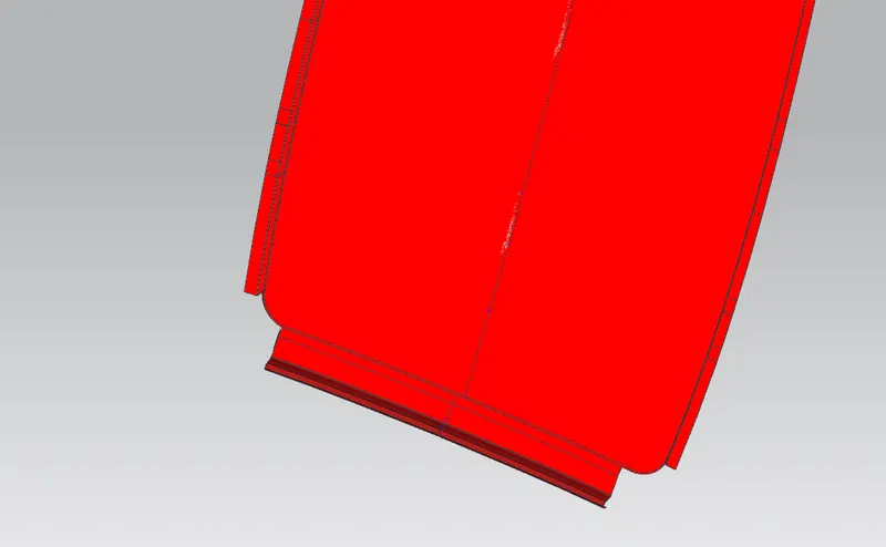
- Offset given class-A surface of roof at specific distance
- Then using law extension both surfaces are join
- Side flanges are design using law extesions only
- Finally fillet is given to all sharp corners
Front roof rail:- Front roof rail is supportive memeber of roof. Does not cover width of the roof that is, it is not attched to side body of vehicle. It is design considering headliners and enough visbility for passengers. It's design is done as follows:-
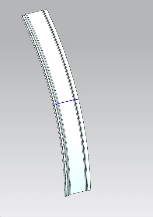
- Master section is provided
- So according to master section by using offset surfaces and law extensions front roof rail is designed
- Again fillet is applied and thicken towards roof side
Center roof rail:- It is called as reinfocement center. It is design to add strength to roof. It's design is done as follows:-
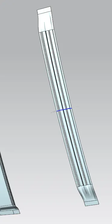
- It is design at center of roof, so a plane is drawn perpendicular to length of car
- Intersection curve is use to drawn curve on center of roof
- Then according to section various curves are offset
- Then using offset surface for roof skin data, horizontal surfaces are designed
- using law extensions design is completed
- Finnally fillet is applied at sharp edges
Rear roof rail:- It is rear side supportive member of roof. It attched with rear door hinge axis. It deasign is done according to master section provided. Its design is as follows:-
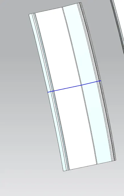
- Master section is provided
- Refering master section design is done
- Finally Edges are blend to provide smoothness to sharp edges
Bow roofs:- It is design for strengthen the roof. Their numbers and position depends on analysis. But it is trail and error method. Firstly we need to design bow roof and then validate its position by analysis. There are two criteria according to different locations, so we need to validate their positions according to that criteria. In this way we can finalyze bow roof. We can emboss roof for additional strength.
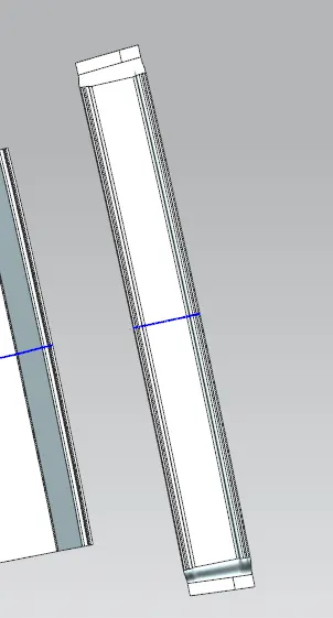
- Master section is provided
- Design is done according to master section
- VAlidating position according to both criteria
- Then finalizing the position of bow roof
Bow roof position calculation criteria:-
a. Heat distortion criteria:- This theory validate the design of roof such that, in warm conditions deformation of the roof will be in limit when load is applied and roof will will achive it's original state when load is removed. Bow roof will provide strength when roof is deform and it will help to atain zero postion. In the following way it is perform:-
- This is the validating formula:- W = [1.73 x 10^(-3) x L] + [1.85 x 10^(-8) x (R^2)/t] + [ 1.10x10^(-3) x l] - 2.68
Where
L = Roof Length in X-Direction[mm](Roof dimension in 0-Y)
R = Roof curvature
R = 2(Rx*Ry)/(Rx+Ry)
Rx = X curvature
Ry = Y curvature
t = Roof plate thickness [mm]
l = Bow Roof Span [mm] - If W is below 2 then the position will be OK otherwise it will be NO GO and we need reconsider position of bow roof.
- For Rx we need to project curve at 300mm from OY axis. Then we need to offset it 100mm on both sides. By drawing curve in perpendicular direction to this curves at center of two bow roofs or bow roof and rail. We will get 3 intersection points. BY drawing three point arc we can find radius of curvature and it is menstion as Rx
- For Ry We need to project center curve of two bow roof and then need to offset two curves at 100 mm distance from both the sides. Then we need to drawn curve at 300mm from OY axis. Then draw curve at intersection points and its radius will be Ry.
- l will be distance between outermost points of BOW-roof dimensions.

- As we can see W value is under 2.7, so design and position of all bow roofs passes the criteria.
b. Snow load condition:- This theory validate the strength of the roof by examining the mean position of roof. Due to snow load roof will get deformed but after the removal of snow load, roof need to attain it's mean position without permanent deformation. In the following way this test is perform:-
- This will be the validating formula:- Qr = [Iy x t2] / [α x s x [(Rx + Ry)/2]2 x 10-8]
Where
α = My x Lx2 x 10-12 , My = Y(Ly-Y)
t = Roof plate thickness [mm]
Ly = Distance between the front and rear roof Rails on the Vehicle along with 0Y[mm]
Length of Roof panel with the center point between Roof rail Front /Rear as the reference point of the front and the rear.
Lx = Distance between the Left and Right end of the roof on the Roof BOW [mm]
Width of the roof panel exposed on the surface.
Y = Distance front Front Roof Rail to Roof BOW[mm]
s = Distance for which Roof BOW bears divided load [mm]
s = L1/2 + L2/2
Iy = Geometrical moment of inertia of Roof BOW (Y cross-section )[mm4]
Rx = Lateral direction curvature radius of roof panel Y cross-section on Roof BOW [mm]
Roof panel curvature Radius of the Length Lx in Front view
Ry = Longitudinal Direction curvature radius of the Roof panel X cross-section on Roof BOW [mm]
Roof panel X curvature radius of length s in Side view - Judmental condition will be Qr ≥ 3.1 and 250 ≤ s ≤ 380

- As we can see Qr value is above 3.1, so our design is passes the criteria.
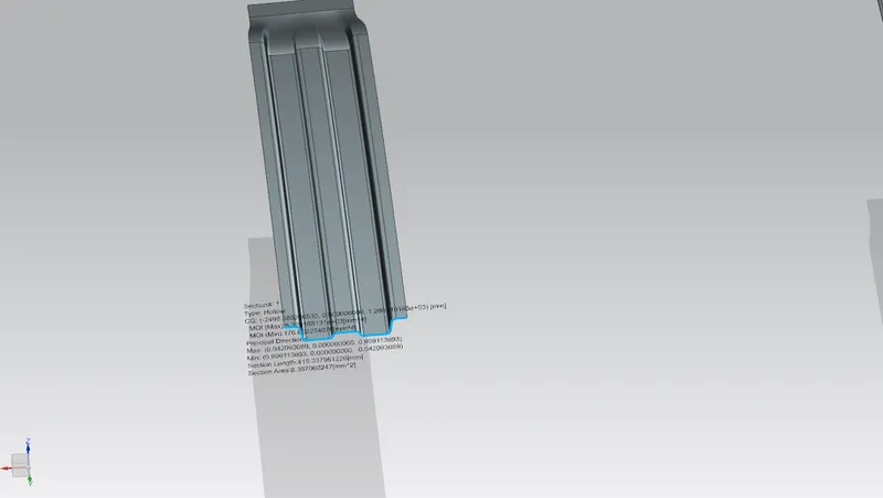
- Geometrical moment of inertia:- It is direct measurement of strength. Higher the MOI higher will be the strength. We can analyse the MOI by NX CAD software. We use minimum MOI to validate our design at a maximum safety. It will give us result of strength even at portion which has minimum MOI.
Bow roof sectional analysis:-
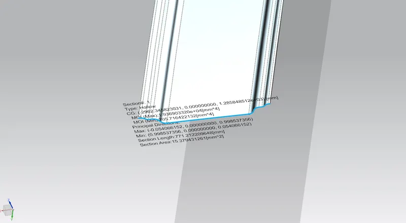
Central rail sectional analysis:-
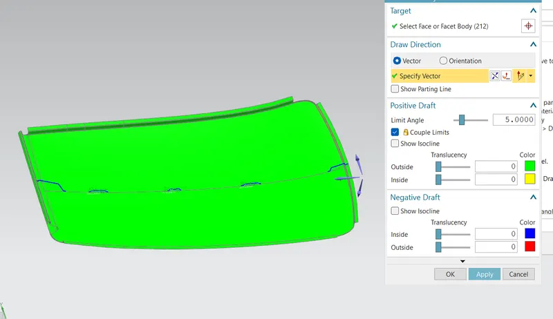
Draft Analysis:- It is perform for the feasibility of manufacturing. Generally supplier provide us minimum draft angle possible. In our case we consider it as 5 degree. SO draft analysis will ensure that all the flanges are greater than 5 degrees and are in the positive direction.
Draft analysis of roof:-
Draft analysis of other parts:
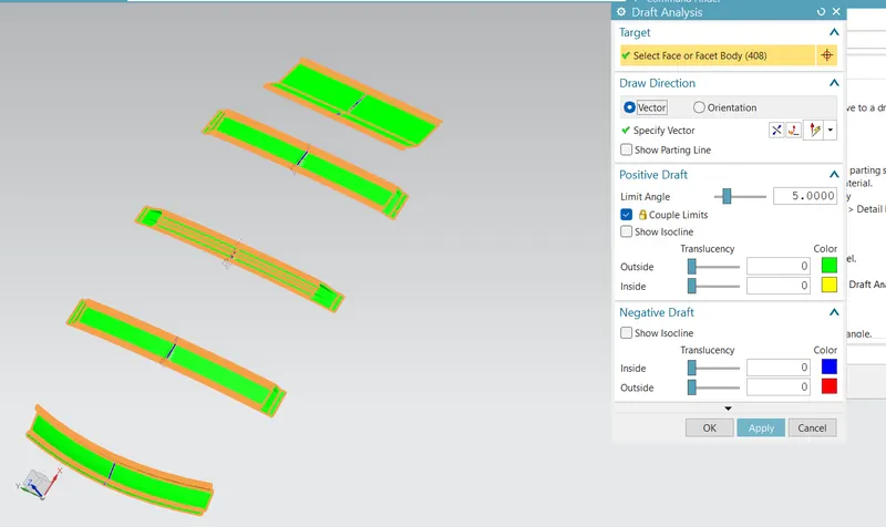
The green colour ensures feasibility in manufacturing of roof and other parts.
Conclusion:- In this way design of roof is done according to design and manufacturing consideration. Various other parts are also design such as bow roof and rails. Some analysis is must before sending design to CAE team which is also done.