Project 2 Thermal modeling of battery pack
AIM:
For a 10 cell series lithium ion battery model simulate the thermal effects and compare life cycle performance at various temperatures, charge and discharge rates using MATLAB.
- For a 10 cell series lithium ion battery model simulate the thermal effects and compare life cycle performance at various temperatures, charge and discharge rates using MATLAB.
Battery thermal management system controls the temperature of the battery by cooling, heating, insulation and ventilation.
- A cooling function should be installed in battery to prevent thermal run away and keep the battery temperature in control
- A heating function such as PTC heater is required to help the battery pack reach its optimum temperature range in a short time in col countries.
- A good insulation should be used that can slow down the fall or rise in battery temperature especially when the vehicle is parked outdoors to protect it against extreme cold conditions or extreme hot conditions.
- Ventilations is required so as to remove the hazardous gases within battery pack. In some systems such as air systems, this functions is combined with cooling and heating systems.
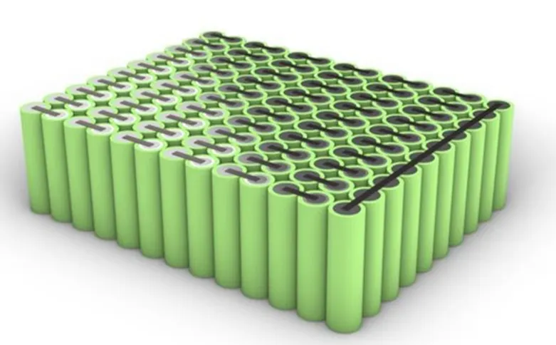
Battery pack is defined as a set of identical batteries which can be configured in series, parallel or a combination of both so as to achieve the desired voltage and capacity. The term battery pack is used in various applications like cordless tools, remote control cars and battery electric vehicles. Components of battery pack include individual batteries and interconnects provide electrical conductivity between them.
To make the battery pack durable and less prone to damages mechanical design of the battery pack should be taken care of. As shown in the block diagram below a typical battery pack design procedures in which the blocks in golden yellow are part of the mechanical design.
SIMULINK MODEL
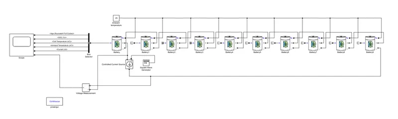
The following blocks that were used for the modelling of the model:
- Battery
- Controlled current source
- Square wave generator
- Voltage measurement
- Bus selector
- Power gui block
- Scope
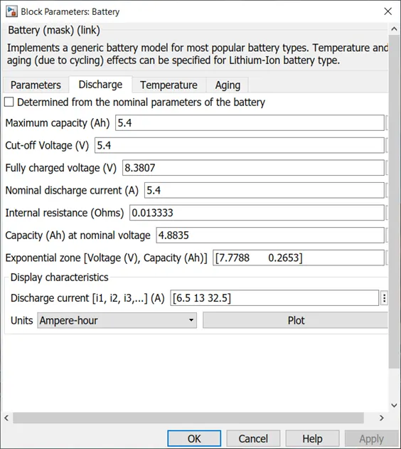
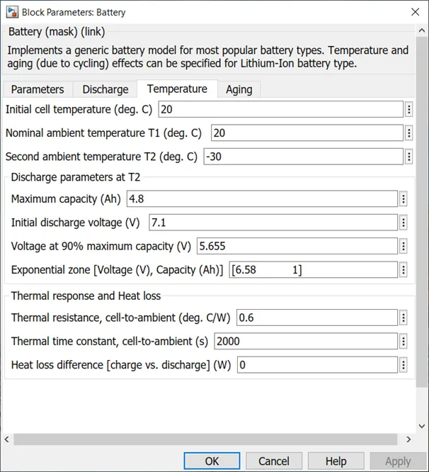
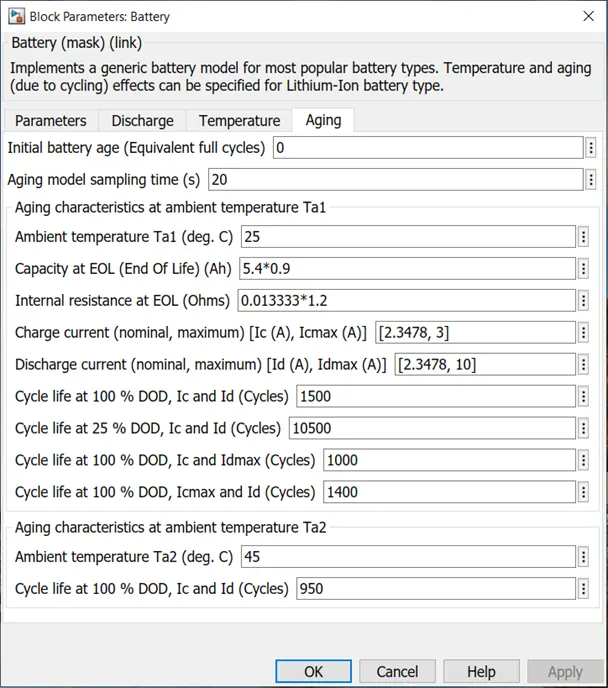
- BATTERY
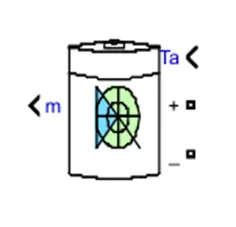
This block creates a generic dynamic model parameterized to represent most popular types of rechargeable batteries.
Lithium-ion batteries require fewer maintenance and operational costs are less. The average life of a lithium-ion battery is 8 years. The lithium-ion battery has significant environmental benefits over fossil fuels. With increase in electric vehicle, we have seen an immediate impact on the reduction of carbon emission.
- CONTROLLED CURRENT SOURCE
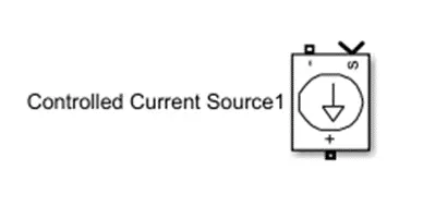
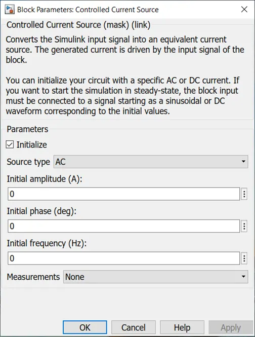
The controlled current source block converts the Simulink input signal into equivalent current source. The positive current direction is as shown by the arrow in the block icon.
- SQAURE WAVE GENRATOR
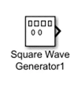
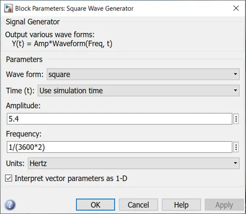
The signal generator block can produce different waveforms like sine, square, saw tooth and random. It can also be expressed in hertz or radians per second.
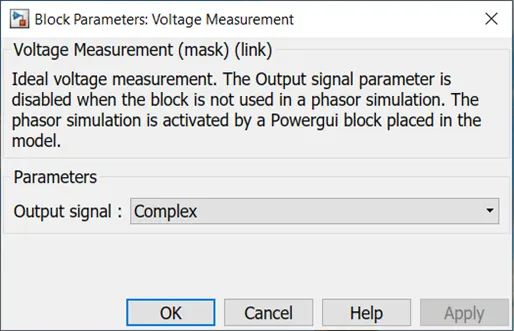
- VOLTAGE MEASUREMENT
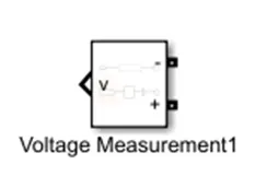
This block measures the instantaneous voltage between two electric nodes.
- BUS SELECTOR

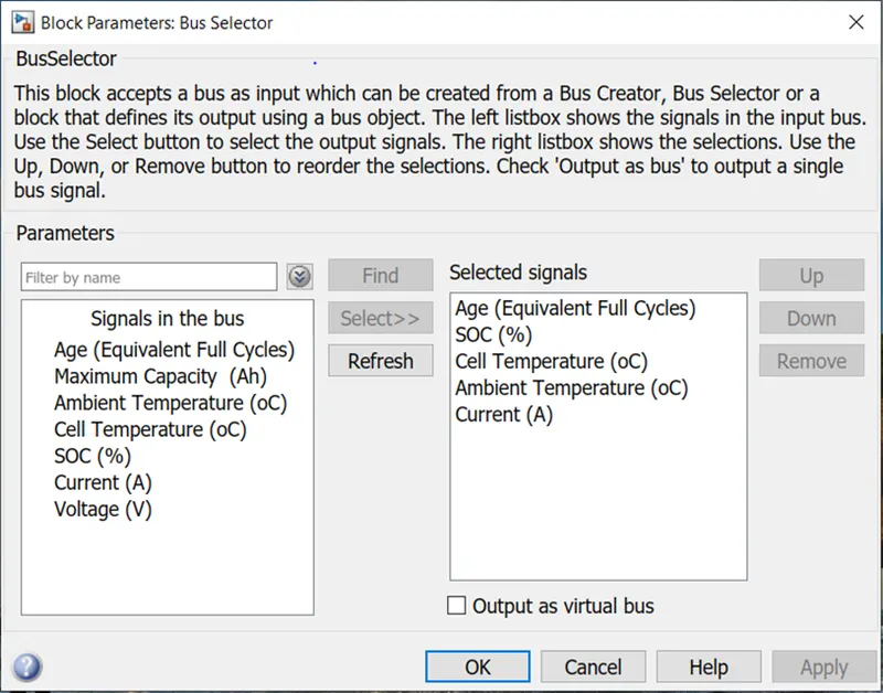
The output of the block specifies subset of elements of bus at its input. The block can output the specified elements as separate signals.
- POWER GUI BLOCK

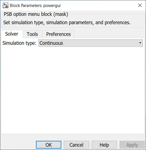
The power GUI block chooses the following methods to solve the circuit:
- Continuous, which uses a variable step solver from Simulink
- Discretization of the electrical system for a solution at fixed time steps
- Phasor solution
This block is used for steady state and simulation results analysis and also for advanced parameter design. This block is required to simulate Simulink model that contain simscape electrical specialized power system blocks.
- SCOPE
Scope is used for viewing the graph of the signals after the simulation is run.
EXPLANANTION
- The configuration of lithium ion battery pack is 10S as all the cells are connected in series. The battery pack charges and discharges using controlled current source and square wave generator.
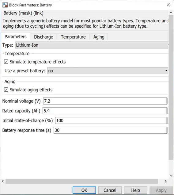
- The temperature and the aging effect of the cells are enabled so as to observe and estimate the temperature and signal effects.
- In this model the age of cell, S.O.C of the battery pack, temperature of the battery pack, ambient temperature and battery pack current is estimated by using a bus selector from any one cell of the battery pack as this battery pack is made by connecting the cells in series.
- The voltage of the battery pack is calculated by connecting a voltage measurement block which is connected across the battery pack in which the first cell positive terminal is connected to the positive terminal of the voltage measurement block and last cell negative terminal is connected to the negative terminal of the voltage measurement block.
- Constant blocks are connected to each of the cells as it indicates the ambient temperature to the cells.
RESULTS
CASE 1: Ambient temperature: 25 ° C and charge – Discharge current: 5.4 A
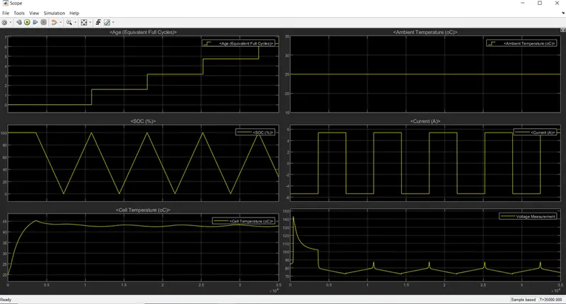
From the graph it is observed that charge – discharge current is similar to cell maximum current capacity which means that the cell charges and discharges at 1C rate. The SOC of the battery pack reduces or charges within an hour which means to complete one cycle it requires 2 hours. Initially the cell temperature increases to 45 and fluctuates within 44 - 45°C. While charging the battery pack temperature slightly increases to 44 and while discharging the temperature reduces to 43°C.
CASE 2: Ambient temperature: 45 ° C and charge – Discharge current: 5.4 A
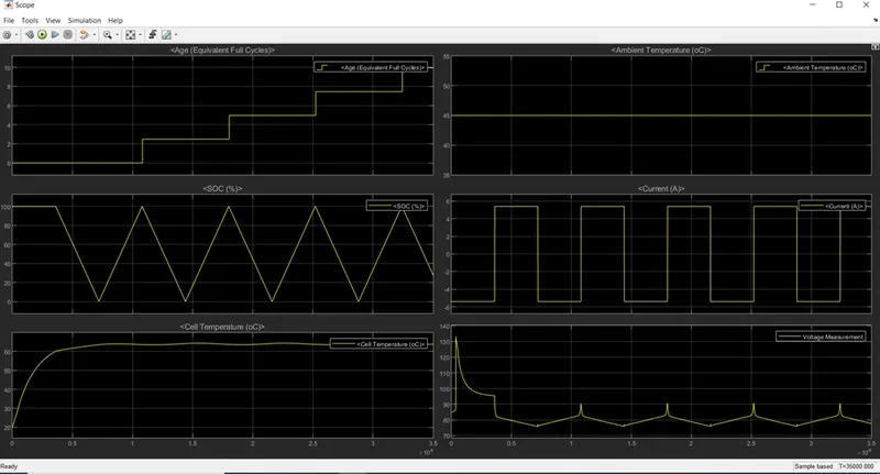
An increase in ambient temperature increases the temperature of the battery pack and hence has an adverse effect on the life cycle of the battery pack.
CASE 3: Ambient temperature: 10 ° C and charge – Discharge current: 5.4 A
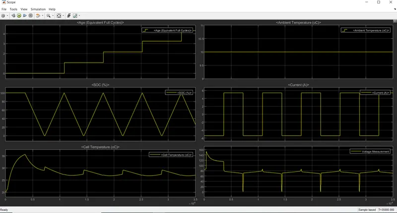
As the ambient temperature reduces to 10° C the age of the battery pack increases. From the graph it is observed that there is significant difference between ambient temperature and cell temperature. Cell temperature varies from 29-35° C.
CASE 4: Ambient temperature: 25 ° C and charge – Discharge current: 3 A
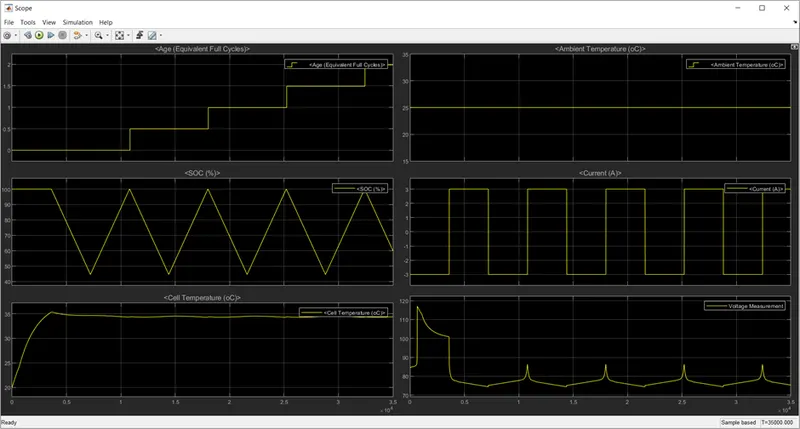
Due to reduction in C rate the battery discharges up to 45%. Since the charge – discharge rate is lower the life cycle of the battery pack would increase and also the cell temperature reduces to 34° C
CASE 5: Ambient temperature: 40° C and charge – Discharge current: 3 A
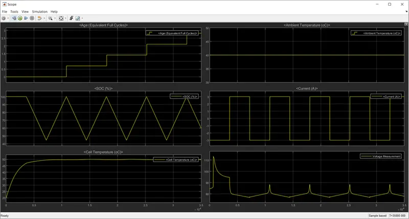
The ambient temperature is 40°C and charge discharge current is 3A which is 0.56C it is noticed that the battery discharges up to 45% . The life cycle of the battery would increase and also the temperature of the battery pacj would stabilise 50°C.
CASE 6: Ambient temperature: 25 ° C and charge – Discharge current: 1A
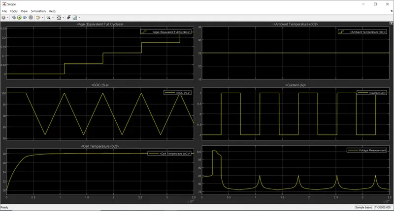
At an ambient temperature of 25° C and charge discharge current of 1A which is 0.18C it was observed that the battery pack discharges to 85% .Hence the age increases drastically and cell temperature was found to stabilise at 29° C.
CONCLUSIONS
- As the ambient temperature increases the cell temperature also increases which adversely effects the age of the battery.
- When we decrease the C rate it is found that the age of the battery increases and temperature of the battery pack reduces.