Project 2 Thermal modeling of battery pack
1)
AIM
For a 10 cell series lithium ion battery model, simulate the thermal effects and compare life cycle performance at various temperatures, charge & discharge rates using MATLAB.
OBJECTIVE
For a 10 cell series lithium ion battery model, simulate the thermal effects and compare life cycle performance at various temperatures, charge & discharge rates using MATLAB.
THEORY
These days, lithium ion batteries are primarily used in electric vehicles. To operate these batteries effectively and without damaging them, we must understand their charge and discharge rates. To do this, we simulate the thermal effect of these batteries' cells. By understanding how much temperature rise occurs, we can effectively cool the batteries, extending their lifespan.
cells connected in series with one defective cell; what will happen thermally,This example demonstrates how to effectively replicate a battery pack made up of several series-connected cells. Additionally, it demonstrates how a flaw in one of the cells may be added to observe the effects on battery performance and cell temperatures. For efficiency, it is not enough to merely join cell models in series to model identical series-connected cells. The terminal voltage is scaled up by the number of cells instead, and one cell is used. Changes to the Cell 10 Fault subsystem's metrics, including a decrease in capacity and open-circuit voltage as well as an increase in resistance values, serve to reflect the fault.
A battery is a component that transforms chemical energy into electricity. An electrochemical cell is the system that supports a battery. This process is known as electrochemistry. One or more electrochemical cells, such as those in Volta's initial pile, can make up a battery. Two electrodes are placed one on top of the other in an electrochemical cell.A form of energy created by the movement of electrons is electricity. One electrode in an electrochemical cell undergoes a chemical reaction to produce electrons (more on electrodes below!). and after that, they move to the opposite electrode, where they are consumed. We must examine the parts of the cell and their assembly in greater detail in order to fully comprehend this.
- An apparatus that stores chemical energy and transforms it into electrical energy is a battery.
- Electrons move from one substance (electrode) to another through an external circuit during chemical reactions in batteries.An electric current can be created by the flow of electrons and employed to perform tasks.
- Charged ions also move through an electrolyte solution that is in contact with both electrodes in order to balance the flow of electrons.
- Different electrodes and electrolytes cause various chemical reactions that have an impact on the battery's operation, capacity for storing energy, and voltage.
RESEARCH STUDY
Consider a world devoid of batteries. Our access to all those portable devices would be severely constrained! Our ability to carry our laptops and smartphones beyond the range of their wires would be limited, rendering the new running app you just bought for your phone largely useless.
We do, fortunately, have batteries. The Baghdad battery was a technology employed by the Parthian civilisation in Mesopotamia about 150 BC. It was constructed of copper and iron electrodes and vinegar or citric acid. Archaeologists think these were mostly utilised for religious rituals and were not actually batteries.The Italian physicist Alessandro Volta is credited with creating the battery as we know it. Volta assembled the first battery to convince fellow Italian scientist Luigi Galvani of his thesis. Galvani demonstrated in 1780 that frogs on iron or brass hooks will quiver when their legs were touched with a probe made of a different metal. He referred to it as "animal electricity" and thought that the frogs' internal electrical currents were to blame.
Volta was first astonished by Galvani's discoveries, but he later came to believe that the frogs' tissues were only a conduit for the electric current, which originated in the two dissimilar metals—the hooks from which the frogs were hanging and the probe. He conducted experiments using stacks of layers of silver and zinc interspersed with layers of cloth or paper drenched in saltwater and discovered that a wire attached to both ends of the pile did, in fact, conduct an electric current.Volta discovered that the voltage could be raised by adding more metals to the pile. In 1800, he wrote a letter outlining his findings to Joseph Banks, the Royal Society of London's president at the time. It was a significant event—Napoleon was pleasantly surprised! and the "volt" (a unit of electric potential) was called in his honour as a result of his invention's long-lasting impact.
Lithium ions in batteries travel from the negative electrode to the positive electrode via an electrolyte during discharge and back again during charging. The positive electrode of lithium-ion batteries is made of an intercalated lithium compound, while the negative electrode is commonly made of graphite. With the exception of LFP cells, the batteries have no memory effect, a high energy density, and a low self-discharge rate.
G.N. Lewis started pioneering work on the lithium battery in 1912, but it wasn't until the early 1970s that the first non-rechargeable lithium batteries hit the market. Of all the metals, lithium is the lightest, has the highest electrochemical potential, and has the highest energy density per unit weight.
LITHIUM-ION SIMULINK BATTERY MODEL
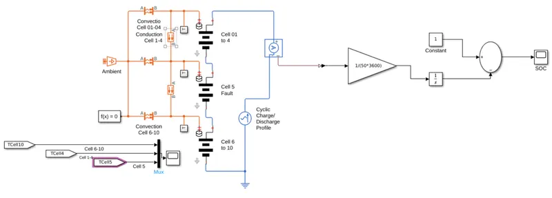
CIRCUIT CONSTRUCTION AND WORKING
In this circuit, we use li-ion cells 1 to 10, temperature sensors, an ambient temperature block, a charge discharge profile that is provided to the ckt, and a from & go to block block in Matlab Simulink.
CELLS TEMPERATURE SUBSYSTEMS
The thermal model and lithium cell block that make up the cell subsystem essentially calculate the temperature and thermal impact for individual cells as well as the overall calculation for the battery pack.
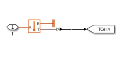
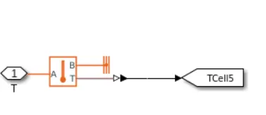
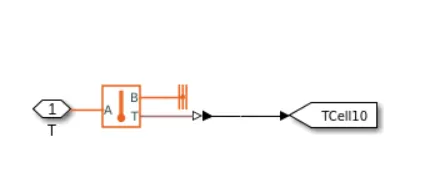
This block mostly comprises of a capacitance value table that is dependent on the inputs SOC and T of an external physical signal. Since it is believed that the capacitance value slowly changes over time, the equation I = C*dv/dt is valid.
SOC and T are inputs to a resistance value (R) table that is dependent on an external physical signal.
The primary branch voltage source for the cell is implemented by voltage value (EM), which also establishes the values for the cell's capacity (C) and state of charge (SOC). The cell temperature, T, is a factor in the defining equations.
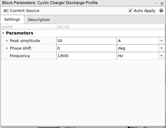
One cell's output is coupled to a source of AC current for cyclic charge/discharge profiling, while the other cell's output is connected to a SOC estimator.
Peak amplitudes for cyclic charge and discharge are set to 50 A. The following is a fundamental AC current source parameter.
other block which are used in lithium ion battery pack are as follows
Battery table based:
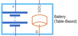
You can expose the two optional ports on the Battery (Table-Based) block by configuring the necessary parameters. The internal state of charge is output via the additional physical signal port, SOC. Use this functionality to modify the load behaviour in relation to the charge state without having to construct a sophisticated charge state estimator. Set the Expose SOC measurement port parameter to Yes in the Main configuration if you want to reveal the SOC port.
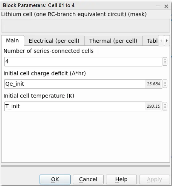
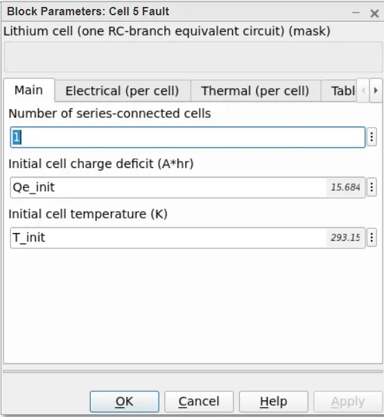
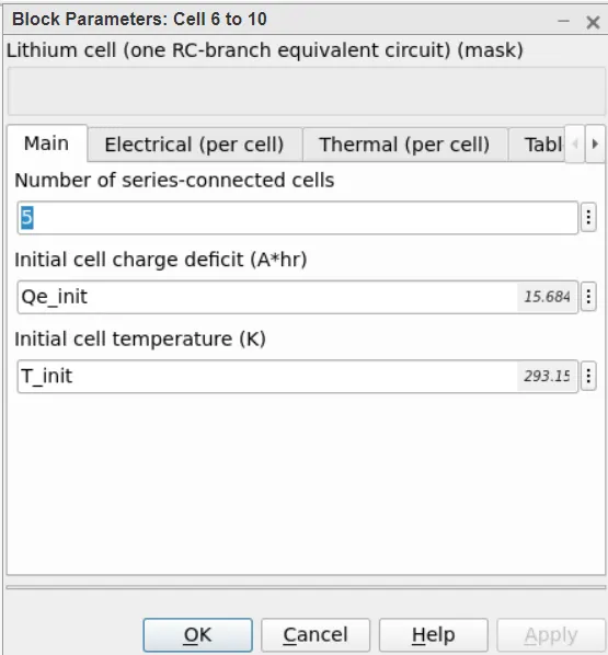
output of one cell is connected with the SOC estimation whereas other output is connected with AC current source for cyclic charge/discharge profile.
The peak amplitudes set to 50 A for cyclic charge and discharge. A basic parameter of AC current source is as
Convective heat transfer:
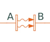
The Convective Heat Transfer block represents heat transfer by convection between two bodies by means of fluid motion.A and B are thermal conservation ports connected to the sites where convectional heat transfer occurs. The heat flow is positive if it flows from port A to port B since the block positive direction is from port A to port B.
Temperature source:

No matter how much heat the system uses, the Temperature Supply block is the ideal source of thermal energy since it can keep the desired temperature at its outlet. According to the value of the Temperature parameter, the source produces constant absolute temperature.
Temperature sensor:

A device that detects the temperature difference measured between two sites without generating any heat is what the Temperature Sensor block symbolises as an ideal temperature sensor. Thermal saving ports called Connections A and B link to the two locations where temperature is being measured. The temperature difference value is output by physical signal port T. Block positive movement is in the port A to port B direction. T = TA - TB is used to calculate the temperature being measured.
Thermal reference

The Thermal Reference block represents an absolute zero temperature point, or a thermal reference point, from which all system temperatures are calculated.
Electrical reference:

An electrical ground is represented by the Electrical Reference block. All blocks with direct ground connections must have their electrical conserving ports connected to an electrical reference block. A model must have at least one Electrical Reference block if it has electrical components.
Solver configuration:
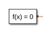
For the purpose of simulating a physical network, each connected SimscapeTM block diagram needs solver configuration information. Before you can start simulating, your model needs some solver parameters, which are specified in the Solver Configuration block. It is necessary to connect exactly one Solver Configuration block to each topologically unique Simscape block diagram.
STATE OF CHARGE ESTIMATION
- The Coulomb counting method calculates SOC by measuring the battery's discharge current and integrating it over time.
- This component outputs the battery SOC% and accepts current as input. For SOC estimate, a current sensor block is utilised and attached.
- This circuit uses the coulomb counting method to measure the battery SOC%. SOC% is the output, and current is the input. The battery's initial SOC is taken to be 100%.
- An effective example demonstrates how to replicate a battery pack made up of several series-connected cells. Additionally, it demonstrates how a fault can be put into a cell to see the effects on battery performance and cell temperatures.

RESULTS OBTAINED:
VARAIATION CELL PARAMTERS at 293 k
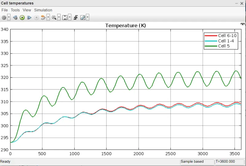
VARAIATION CELL PARAMTERS at 300 k
VARAIATION CELL PARAMTERS at 315 k
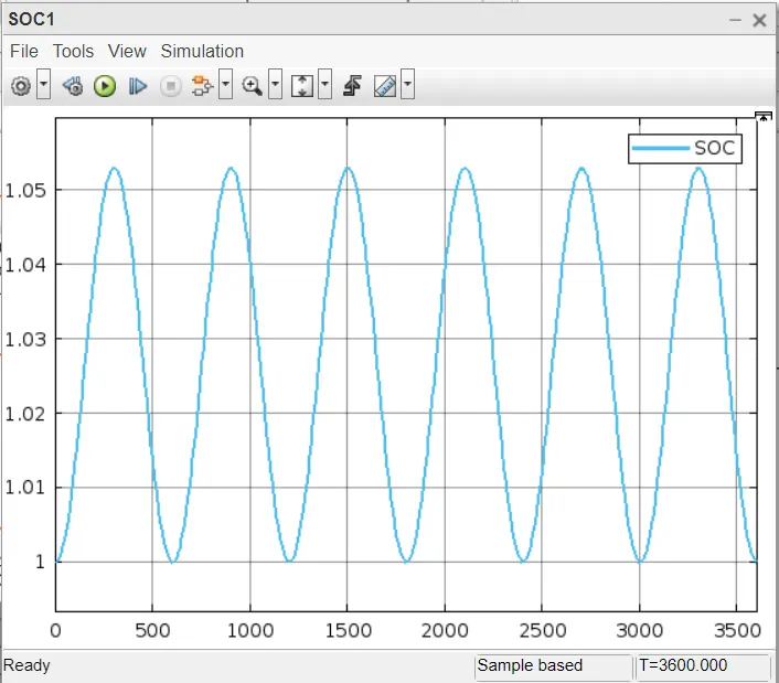
VARAIATION CELL PARAMTERS at 293 k
RESULT EXPLANATION
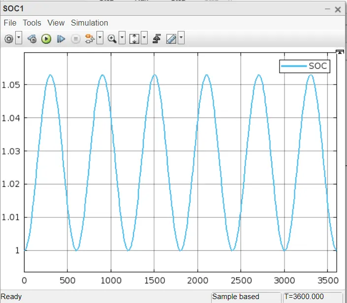
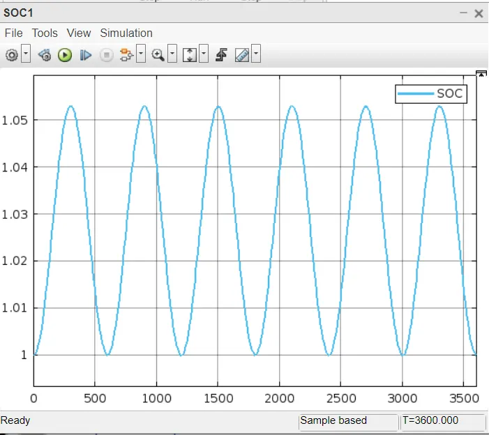
- Using MATLAB, we simulate the thermal impacts and compare life cycle performance for a 10 cell series lithium ion battery model at varied temperatures, charge and discharge rates. These are the outcomes.
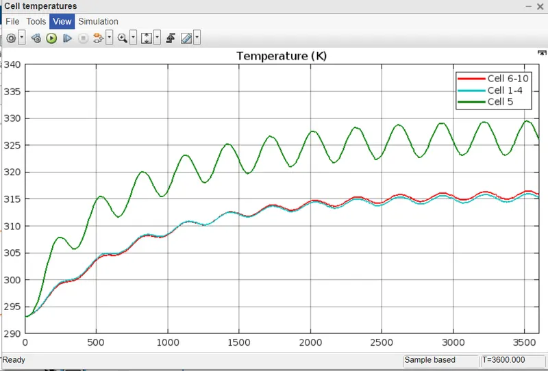
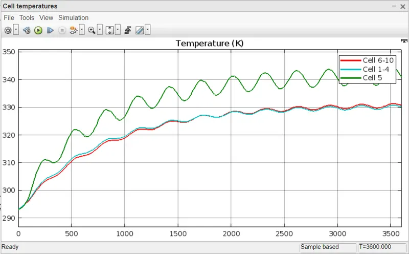
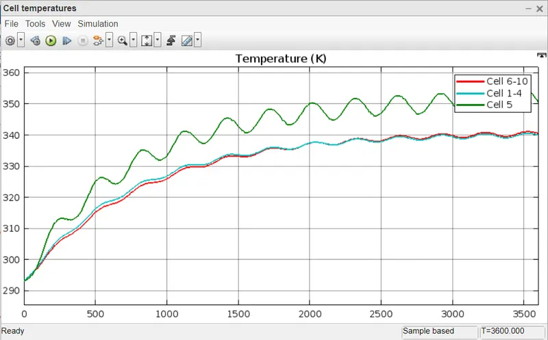
- Normal cells range from 1 to 4. 5th cell has a problem. The results above are identical under all conditions, but when the circuit is run on this drive cycle profile because the fifth cell was defective, it will show temperature rise higher than any other cell, reducing the life cycle of cell, and cell even can get damaged. 6-10 cell is normal cell as we are simulating thermal effect on we give Cyclic Charge/ Discharge Profile to circuit the waveform.
- The 1-4 and 6-10 cell temperatures are close to 316k as we present the findings' temperature as 300 k, or 26.85°C.
- Nonetheless, the temperature of the fifth defective cell rises to 330k, or 56.85°C, and the drive cycle—a cyclic charge/discharge drive cycle—is displayed.
- In condition 2, we set the temperature to 315 k, which is 37.85°C. Cells 1-4 and 6-10 had temperatures close to 326 k, while the fifth defective cell has a temperature of 340 k, which is 66.85°C.
- The temperature in condition two is set at 325 k, or 51.85°C, while the temperatures in cells 1-4 and 6–10 are close to 340 k, or 80.85°C. The driving cycle, known as the Cyclic Charge/Discharge drive cycle, is also displayed.
- Also we will find out the effects at 293K ie 23°C.is found out and the results at this temperature is also notably almost the same itself.
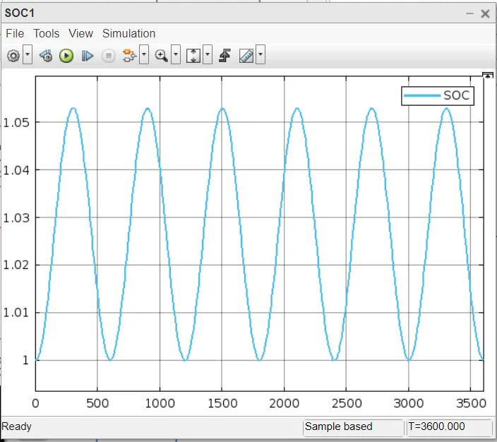
- The state of charge is obtained almost same in all the cases.
CONCLUSION
We modelled the thermal effect and compared at different temperatures. Faulty cells' temperatures rIse more than usual throughout the provided charge and discharge cycles, and as a result, the cell could be damaged and the battery's performance could be affected.