Thermal modeling of battery pack
Objective -
For a 10 cell series lithium ion battery model, simulate the thermal effects and compare life cycle performance at various temperatures, charge & discharge rates using MATLAB.
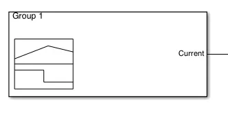 |
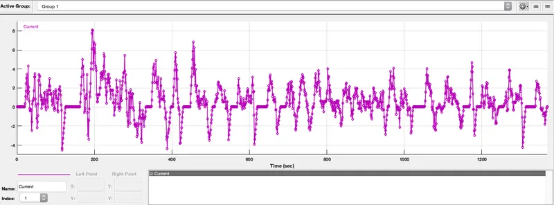
This block creates a current charge discharge cycles |
 |
Controlled current source block will create a output current corresponding to the input physical signal. |
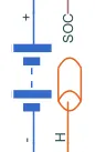 |
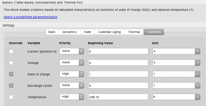
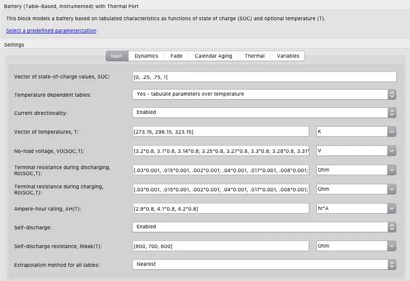
This block models a battery based on tabulated characteristics as functions of state of charge (SOC) and optional temperature (T). |
 |
This block represents an ideal energy source in a thermal network that can maintain a constant absolute temperature at the port regardless of the heat flow rate. |
 |
This block models heat transfer in a thermal network by convection due to fluid motion. The rate of heat transfer is proportional to the temperature difference, heat transfer coefficient, and surface area in contact with the fluid. |
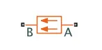 |
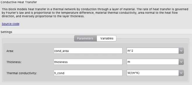
This block models heat transfer in a thermal network by conduction. |
 |
This block measures temperature in a thermal network. There is no heat flow through the sensor. The physical signal port T reports the temperature difference across the sensor. The measurement is positive when the temperature at port A is greater than the temperature at port B. |
 |
This block represents a reference point in a thermal network where the temperature is equal to absolute zero. |
 |
The voltage-current (V-I) relationship for a linear resistor is V=I*R, where R is the constant resistance in ohms. |
 |
Electrical reference port. A model must contain at least one electrical reference port (electrical ground). |
 |
Scope block used to plot the obtained results with respect to the simulation time. |
To create a thermal model of the battery we have used a table based battery block with instrumented thermal port. The nominal capacity of each cell is 4.2Ah and the nominal temperature of cell is 298.15K. The input to the battery is given by the controlled current source using a signal builder block.
Each cell is modelled usng a table based model.
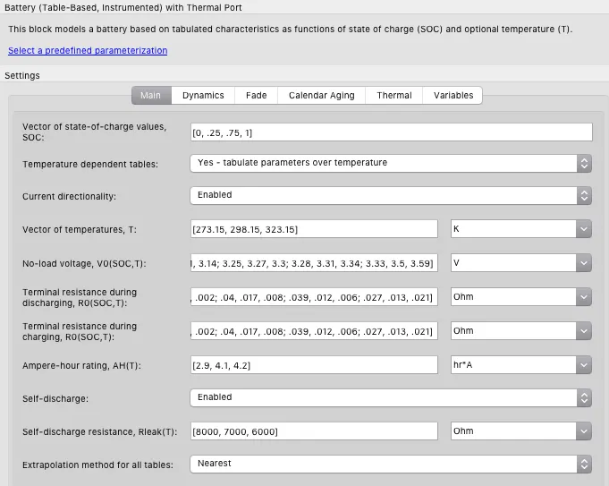
It is assumed that each cell is completely charged initially. This is done by taking the initial value of variable State of Chrge to 1.
The UDDS data can be seen below. This has been taken as an input using the signal builder block. This current is drawn from the battery using a current source.
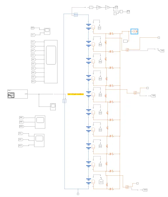
The complete model can be seen below. Here, 10 cells are connected in series. The 5th cell is faulty and has lower resistance than other cells. The heat transfer is observed between the packs by conduction and convection block which are modes of heat transfer.
Conductive Heat Transfer
Heat transfer by conduction
Thermal Elements
The Conductive Heat Transfer block represents a heat transfer by conduction between two layers of the same material. The transfer is governed by the Fourier law and is described with the following equation:
Q=k·AD(TA−TB)
where
| Q | Heat flow |
| k | Material thermal conductivity |
| A | Area normal to the heat flow direction |
| D | Distance between layers (thickness of material) |
| TA,TB | Temperatures of the layers |
Connections A and B are thermal conserving ports associated with material layers. The block positive direction is from port A to port B. This means that the heat flow is positive if it flows from A to B. There is conduction block between each cell.
Convective Heat Transfer
Heat transfer by convection
Thermal Elements
The Convective Heat Transfer block represents a heat transfer by convection between two bodies using fluid motion. The transfer is governed by the Newton law of cooling and is described with the following equation:
Q=k·A·(TA−TB)
where
| Q | Heat flow |
| k | Convection heat transfer coefficient |
| A | Surface area |
| TA,TB | Temperatures of the bodies |
Connections A and B are thermal conserving ports associated with the points between which the heat transfer by convection takes place. The block positive direction is from port A to port B. This means that the heat flow is positive if it flows from A to B.
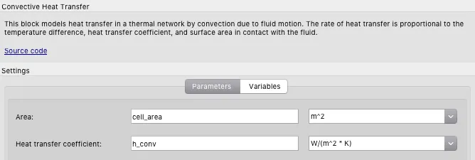
The script file is used to establish the thermal values
cell_area = 0.1 m^2
h_conv = 5 W/(m^2 * K)
cond_area = 1e-3 m^2
thickness = 0.1 m
h_cond = 200 W/(m*K)
The connection of two cells can be seen below. Using the SOC port we measure the SOC of each cell.
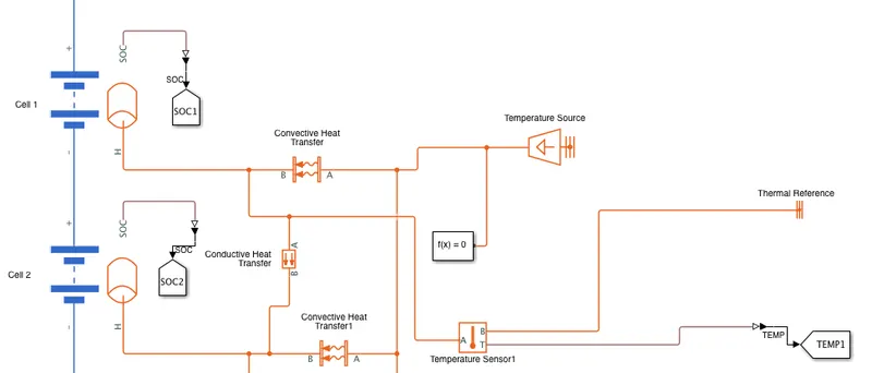
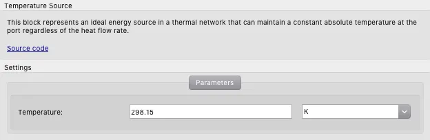
The temperature source is the ambient temperature. We will simulate the system, for various ambient temperatures. The ambient temperature is dependent on other sources of heat like motor and other automobile components. The weather also plays a role here. The cell temperature is measured using temperature sensor.
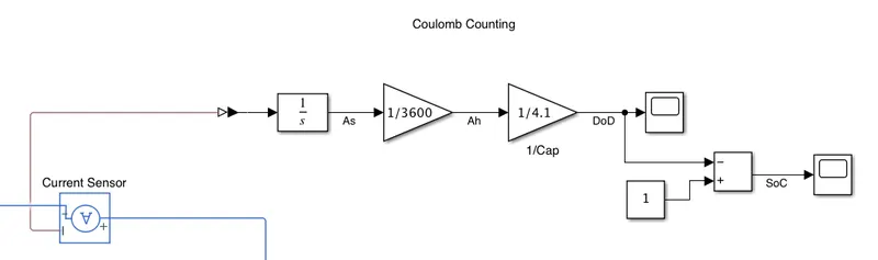
Battery SOC
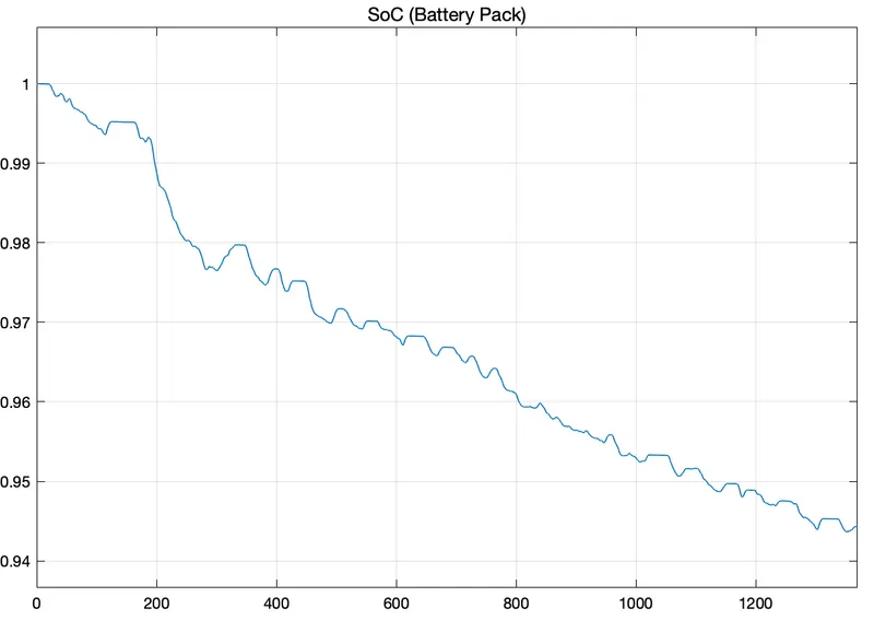
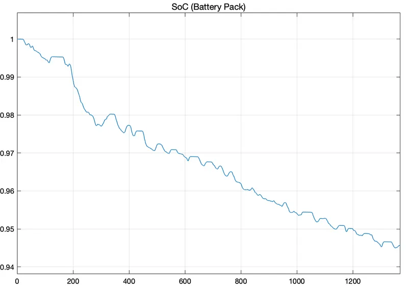
The coulomb counting method is used for SOC estimation of the battery. The battery discharge is current is used to calculate he SOC.
Faulty Cell
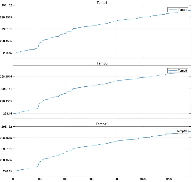
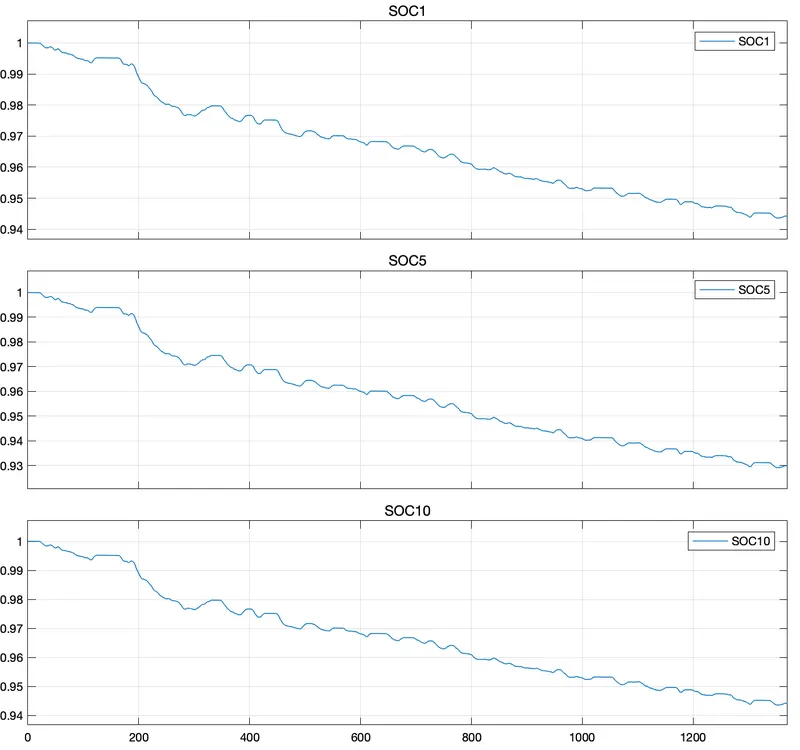
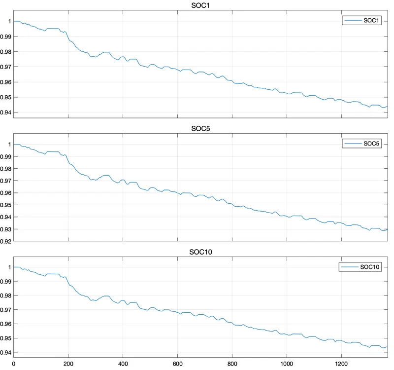
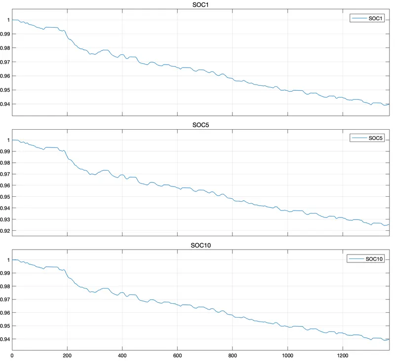
Cell 5 is taken as a faulty cell. Here, the fault is generated by decreasing the internal resistance of the cell. The temperature of the faulty cell is given by Temp5 and the SOC is given by SOC5.

Results
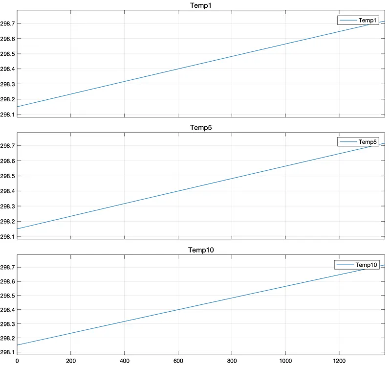
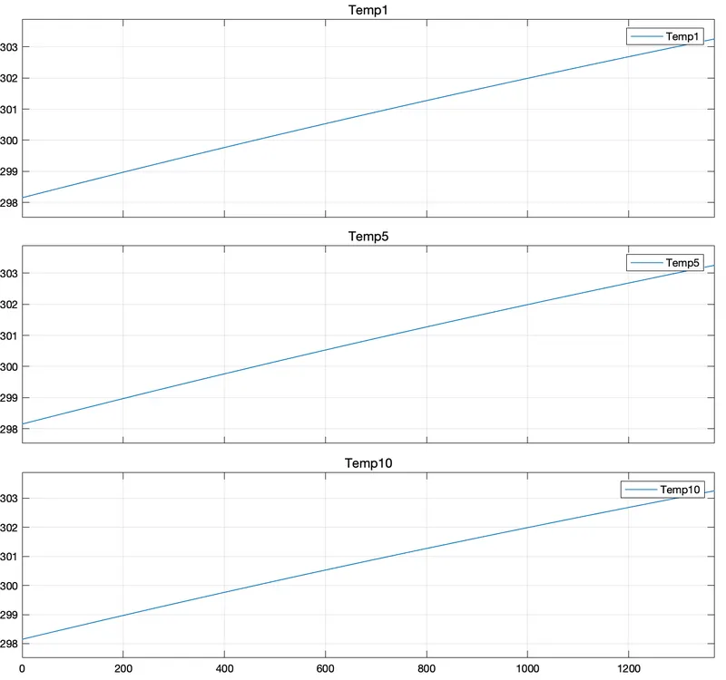
Here different cases are considered, where the ambient temperature varies for each case. The SOC and temperature of cell 1, cell 5 (faulty) and cell 10 are potted for each case. We also consider case when the thermal properties of the battery pack changes.
Case 1 : Ambient temperature is 298.15 K
cell_area = 0.1 m^2
h_conv = 5 W/(m^2 * K)
cond_area = 1e-3 m^2
thickness = 0.1 m
h_cond = 200 W/(m*K)
Case 2 : Ambient temperature is 323.15 K
cell_area = 0.1 m^2
h_conv = 5 W/(m^2 * K)
cond_area = 1e-3 m^2
thickness = 0.1 m
h_cond = 200 W/(m*K)
Case 3 : Ambient temperature is 323.15 K
cell_area = 0.1 m^2
h_conv = 50 W/(m^2 * K)
cond_area = 1e-3 m^2
thickness = 0.1 m
h_cond = 200 W/(m*K)
Conclusion
We see that the ambient temperature also changes the cell temperature. The faulty cell 5 has lower SOC at the end of the charge discharge cycle. In this model we have also changed the coefficient of convection and seen the result on SOC. The material selection of the battery pack clearly impacts the the cell SOC at the end of charge discharge cycle. The battery pack SOC is calculated using coulomb counting method. This value closely relates to the cell SOC however, there remains a difference.
It can be seen that high ambient temperature can damage the cell and reduce the performance of the battery. Moreover, if we operate the battery at a high temperature than the rated temperature then the faulty cell will discharge much faster than other cells and lead to further reduction in battery performance.