DC Motor Control with Simulink
1. A. Explain a MATLAB demo model named ‘Speed control of a DC motor using BJT H-bridge’.
Ans: The model simulates the first quadrant operation and third quadrant as seen in figure 1.
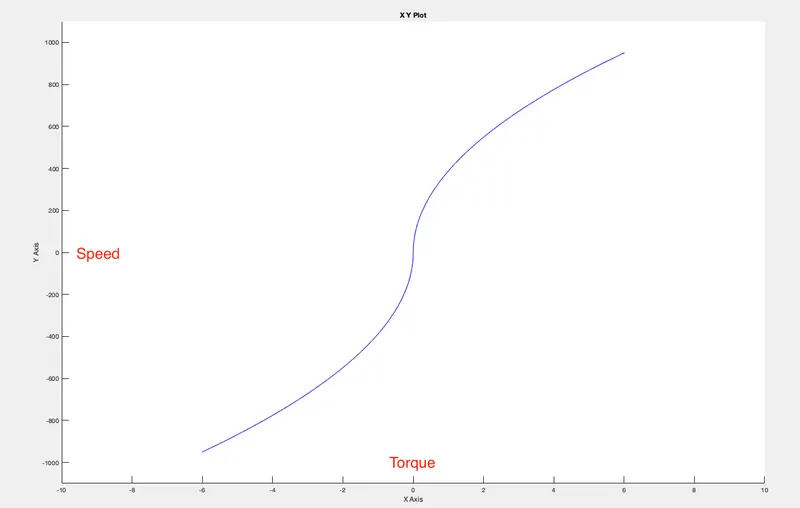
Figure 1
For the fist quadrant operation, the battery current is shown in Figure 2
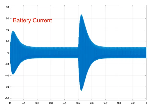
Figure 2
1st Quadrant Operation:
In the first quadrant operation, Q1 and Q4 are given the same pulses at 75% duty ratio. Q2 and Q3 remain turned off. When Q1 and Q4 are turned ON, the current increases in the DC motor and the battery is discharging. When Q1 and Q4 turn off, Diodes D3 and D2 get forward biased and start conducting. Thus, the battery gets discharged.
3rd Quadrant Operation:
In the 3rd quadrant operation, Q2 and Q3 are given same pulses, while Q1 and Q4 remain turned off. When both Q2 and Q3 are turned ON, the current increases in the DC motor but in reverse direction, thus the torque and speed are negative. But the battery is discharged in this condition. When both Q2 and Q3 are turned off, the diodes D1 and D4 are tirned ON and the battery gets charged.
B. Comment on the armature current shoot-up from the scope results.
Ans: The current shoot up happens when the back emf is less as compared to the voltage accross the armature(Va). This is true in the transient condition. When the speed increases from 0, the back emf (Eb) is zero, thus the current shoots up. When the armature voltage becomes negative, but the speed is positive, there is a even greater difference between Va and Eb and thus armature current shoots even more.
Ia (Armature Current) = (Va - Eb)/Ra
C. Refer to the help section of ‘The Four-Quadrant Chopper DC Drive (DC7) block’. Compare it with the H-bridge model.
Ans: ‘The Four-Quadrant Chopper DC Drive (DC7) block’ is a speed control drive for DC motor. Here the input is a reference speed value.
| Speed control of a DC motor using BJT H-bridge | Four-Quadrant Chopper DC Drive (DC7) block |
| Duty ratio is constant at 75% | Duty ratio is variable and controlled based on the reference speed. |
| No speed control | Speed control is implemented |
| No feedback for armature current | Armature current control is regulated |
| No current limit is implemented | Current limit can be implemented |
| Armature current shoots up due to lack of control | Armature current shoot up is limited due to implementation of feedback loop |
| Speed change is fast | Speed change is slow due to current control loop |
2. Develop a 2-quadrant chopper using simulink & explain the working of the same with the relevant results. (Refer to article - Multiquadrant operation of motor )
Ans:
Figure 3 shows the two quadrant chopper. From 0. to 1 sec, the duty ratio is maintained to be 75%. Duty ratio is changed to 25% at 1sec. In the fist quadrant, the current and voltage applied are positive. Q1 and D2 operate in the first quadrant. This is also called forward motoring. Q2 and D1 operate in the second quadrant. Here the voltage is positive but the current is negative. This is also called forward braking.
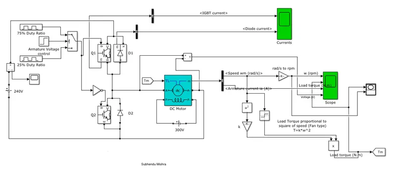
Figure 4 shows the simulated results for the two quadrant chopper.
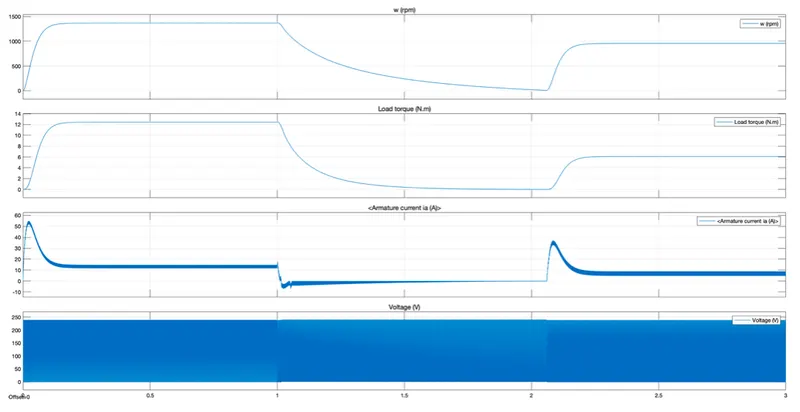
Figure 4
Figure 5a shows the current in switch Q1 and Diode D1
Figure 5b shows the current in swith Q2 and Diode D2
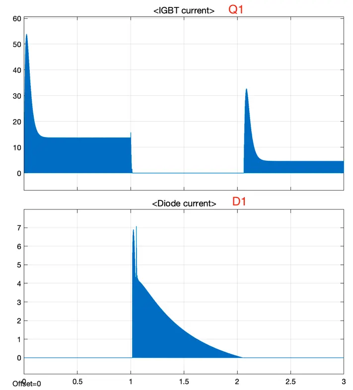
Figure 5a
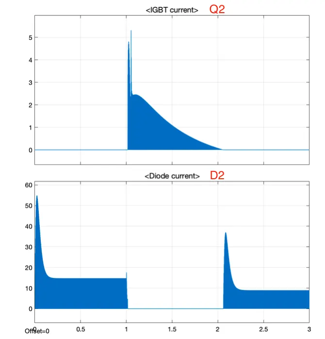
Figure 5b
3. Explain in a brief about operation of BLDC motor.
Ans:
The BLDC motor has 3 phases, with 120 degree mehanical angle with respect to each other as shown in Fig 6. The three windings are AA' , BB' and CC'. The rotor is has permanent magnets inserted.
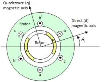
Fig 6 (Ref: Mathworks)
For BLDC motor, we get trapeziodal line-line back emf at each windings as seen in Fig 7.
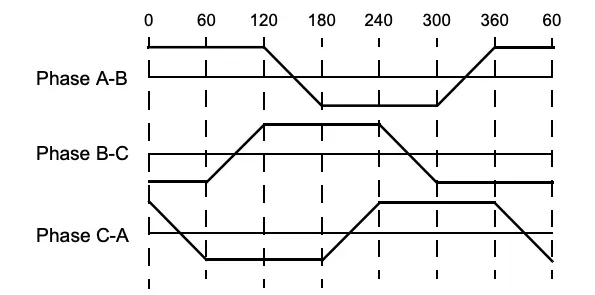
Fig 7 (Ref : http://electrathonoftampabay.org/)
Further, at any given instant only to phases are conduting. The sequence off conduction is maintaned so as to get a rotating stator MMF in the air gap. The sequence can be seen in Fig 8.
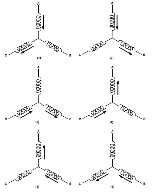
Fig 8 (Ref : http://electrathonoftampabay.org/)
The sequence can be generated using a DC - AC converter as shown in Fig 9.
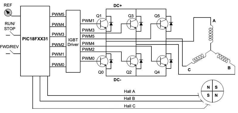
Fig 9 (Ref : http://electrathonoftampabay.org/)
Hall sensors are used to locate the position of rotor and accordingly correct the excitation sequence of the stator windings. For every 60 degree, the same set of switches are turned on. The seqeunce is shown in Fig 10. For each sequence, two switches are turned on. Accordingly DC current flows in the respective phase windings. The sequence can be reversed to change the direction of rotation.
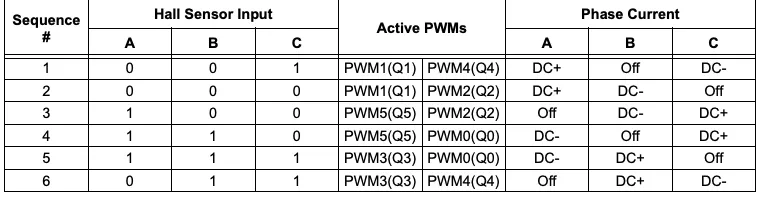
Fig 10 (Ref : http://electrathonoftampabay.org/)