Powertrain Design for Aircraft in Runways
Part 1:
Q1. Search and list out the total weight of various types of aircrafts.
Ans:
Weight class is based are assigned by APO130 based on the TFMS observed aircraft codes. There are 6 categories -- (A) Heavy, (B) B757, (C) Large Jet, (D) Large Commuter, (E) Medium, (F) Small.
(A) Heavy: Any aircraft weighing more than 255,000 lb such as the Boeing 747 or the Airbus A340;
(B) B757: Boeing 757 all series;
(C) Large Jet: Large jet aircraft weighing more than 41,000 and up to 255,000 lbs such as the Boeing 737 or the Airbus A320;
(D) Large Commuter: Large non-jet aircraft (such as the Aerospatiale/Alenia ATR-42 and the Saab SF 340), and small regional jets (such as the Bombardier Canadair Regional Jet), weighing more than 41,000 and up to 255,000 lbs;
(E) Medium: Small commuter aircraft including business jets weighing more than 12,500 up to 41,000 lbs such as the Embraer 120 or the Learjet 35; and
(F) Small: Small, single, or twin engine aircraft weighing 12,500 lbs or less such as the Beech 90 or the Cessna Caravan.
Q2: Is there any difference between ground speed and air speed?
Ans:
Yes, the ground speed is the relative speed of the plane with respect to the ground. Higher ground speed will result in the plane reaching its destination faster.
Air speed is the relative speed between the plane and the air around it or the speed at which air is flowing around the wings of the aircraft.
Q3. Why is it not recommended to use aircraft engine power to move it on the ground at Airport?
Ans:
The aircraft engine is very loud and it becomes unsafe for passengers or crew to be near the ingine when it is running. So, a towing vehicle is used to push the aircraft out of parking and move it on the ground. This needs less trained personnel and is also economical.
Q4. How an aircraft is pushed to runway when its ready to take off?
Ans:
A tug is used to push the aircraft untill it is ready to take to off. Tug is a IC engine or battery operated vehicle. Once the aircraft is ready to move, it is provided with low thust power of the aircraft engine to go along the taxiway. At the runway, full thrust is given.
Q5. Learn about take off power, tyre design, rolling resistance, tyre pressure, brake forces when landing.
Ans:
Engine Take Off Power
Say we consider a Boeing 777 for the question.
MTOW (Max Take Off Weight) = 350,000 kg
Take Off Speed = 74 - 96 m/sec
Take off time (On Runway) = 10 - 30 sec
For the peak power requirement, we take the maximum speed and minimum time.
Power = Energy / Time
Energy = (1/2)*m*v^2
= 0.5*(350,000)*(96^2)
Time = 10 sec
No of engines = 2
Take off Power Required from each Engine = 80,640 kW
Tyre Design / Tyre pressure
Aircraft tyres are re-inforced with Kevlar. They are filled with Nitrogen. They have three layers of rubber laid down in different directions. Moreover, they have 6 times more pressure than normal car tyres.
Rolling Resistance
Rolling Resistance / Rolling Force = Coefficient of friction * mass * g
= 0.02*350,000*9.8
= 68,600 N
Brake forces when landing
Hydraulic brakes are used. Electrical signals are sent to hydraulic actuators of each wheel. Hydraulic force of 3000 pounds/inch^2 is used to force the brake units. Wind spoilers are also used. They create drag and this further assists in braking.
Part B:
Q6. A. With necessary assumptions, calculate the force and power required to push / pull an aircraft by a towing vehicle.
The towing vehicle force and power required is calculated to pull/push a boeing 777. The following assumptions are taken :
1. Coefficient of rolling resistance = 0.02
2. Weight of tow truck = 1000 Kg
3. Weight of Aircraft = 350,000 Kg
4. Maximum Speed of tow truck = 32 Kmph
5. Time to reach peak speed = 10 min
6. Gear Ratio = 1:20
7. Wheel diameter = 0.6468 m
8. Gradeability = 0
The excel file is attached for the calculation.
| Tow Truck Motor Power Calculations | Boeing 777 Tow Truck | ||||
| Rolling Resistance | |||||
| Curb Weight (Kg) | 1000 | ||||
| Payload(Kg) | 350000 | Tyre | |||
| Coefficient of Rolling Resistance (urr) | 0.02 | ||||
| Rolling Resistance Force (N) | 68796 | Tow Truck Tyre | |||
| Dia | 646.8*2 | mm | |||
| Air Drag Calculation | Radius | 0.6468 | m | ||
| Air Density (Kg/m3) | 1.25 | ||||
| Width (m) | 2 | Total Traction Force | 74056.83951 | N | |
| Height (m) | 2 | ||||
| Frontal Area (m2) | 4 | Gear | 20 | (1:20 Gear Ratio) | |
| Drag Coefficient | 0.308 | ||||
| Top Speed(kmph) | 32 | Wheel Torque (Nm) | 47899.96379 | (Maximum) | |
| Air Drag(N) | 60.83950617 | ||||
| Motor Torque (Nm) | 2394.99819 | (Maximum) | |||
| Total Power at given speed (kW) Air Drag + Rolling Resistance | 612.0607956 | kW | |||
| Speed of axel | 13.74287089 | rad/s | |||
| Hill Climbing | |||||
| Angle (Degree) | 0 | Speed of shaft | 274.8574177 | rad/s | |
| Speed during hill climbing (kmph) | 0 | ||||
| Force(N) | 0 | Power (Rated) | 658.2830178 | kW | |
| Hill Climbing Power (kW) | 0 | kW | |||
| Power (Rated) Each Motor | 164.5707545 | kW | |||
| Acceleration Calculation | |||||
| Final Speed (0 to x kmph) | 32 | ||||
| Acceleration Time (sec) | 600 | ||||
| Acceleration (m/s2) | 0.014814815 | ||||
| Acceleration (N) | 5200 | ||||
| Acceleration Power(kW) |
Q6. B. Develop the model for the calculated force and power using Simulink.
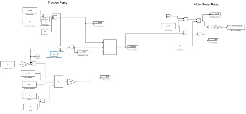
Q7 A. Design an electric powertrain with type of motor, it’s power rating, and energy requirement to fulfill aircraft towing application in Simulink. Estimate the duty cycle range to control the aircraft speed from zero to highest. Make all required assumptions. Prepare a table of assumed parameters. Draw a block diagram of powertrain.
(Hint :DC7 Block)
Ans:
We consider the towing vehicle of part A. Since the power requirement is very large, we assume there are 4 DC motor drives on each wheel pulling the tow truck.
Battery Voltage (4 packs) : 500 V (Li Ion)
Speed = 10 Kmph
Time of towing = 10 min
Total Power = 658 kW
Power output from each DC motor = 164 kW
Rating of each DC motor = 225 HP
Peak Armature Current = 338 A
Battery Capacity (Individual pack) = 28 kWh
Total Battery Capacity = 112 kWh
Shaft speed at 10 Kmph = 822 RPM
Torque output of each DC motor = 600 Nm
We are simulating each DC motor drive (164 kW)
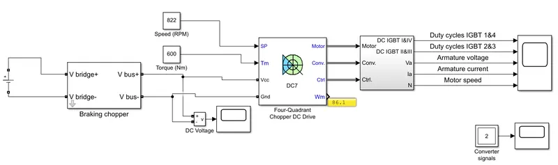
The 4 quadrant chopper can be seen here:
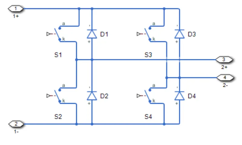
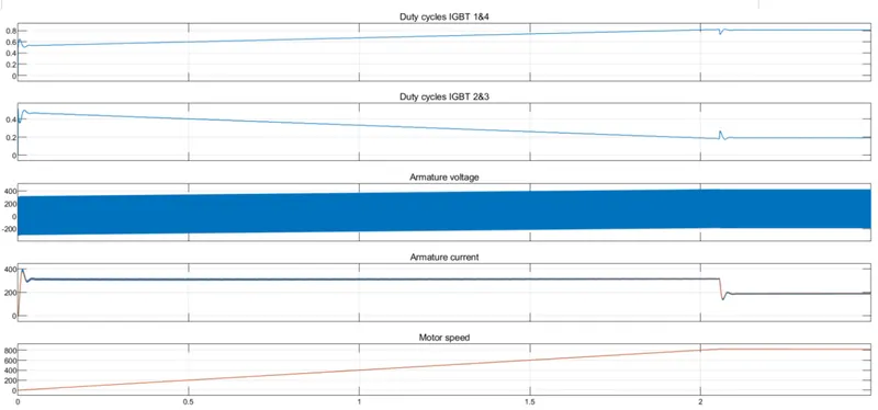
The simulation results and the duty cycle for switch 1 and 4 can be seen here. At the start, the duty ratio of switches 1 and 4 is 0.5 or 50%. The duty ratio for switches 1 and 4 is 0.81 or 81% at the speed of 10 kmph. As the duty ratio of switches 1 and 4 increase, we get a greater average DC voltage at the armature of the DC motor.
Q7 B. Also, Design the parameters in excel sheet.
Parameters are calculated in the excel sheet.