Project 2 Thermal modeling of battery pack
A lithium ion battery uses chemical reactions to produce electricity. The battery is made of many lithium-ion cells. Each cell has two electrodes anode and cathode. Anode is the negative electrode which is a copper foil coated with graphite. Cathode on the other side is the positive electrode which is a metal sheet coated with aluminium. These are also called current collectors. There is electrolyte sandwiched in between with separator on each sides. The electrolyte is made of non-aqueous solution which allow only lithium protons to pass and not the electrons. Separator saves the component isolated with one another and avoids short-circuit. The whole set up in arranged inside the housing to portect it from water, sunlight and other atmospheric substances which may cause corrosion or short-circuit. There more than 1 cell in a battery depending on the performance demand. The cells are connected in series or parallel or may be both again depending on the performance demand.
SERIES CONNECTION
In series, all the cells are connected in such a way that the +ve terminal of cell connects to the -ve terminal of the other cell and so on. In this way, the current remains the same at the output end but voltage adds up as per the no. of the cells. This means that the resistance also adds up in the same manner. The advantage of this connection is that higher voltage levels can be achieved with suc a connection. Drawback of such a connection is that if there is any short circuit in one cell then whole circuit would cut the current supply and there would be no output coming out of such connection.
PARALLEL CONNECTION
The cells are connected in such a way that +ve terminal of one cell is connected to +ve terminal of the next cell and so on. In the same way, -ve terminal of one cell is connected to -ve terminal of the next cell and so on. In this way, the current adds up and the total current output is the adding of current passing through each cell in the order with voltage remaining same. The voltage of 1 cell is what the total output voltage is in this case. The resistance in such a connection is such that resistance offered by each cell is the addition of the reciprocal resistance values. The sum of all resistance is the total resistance output. This connection is useful if higher current values are required. If any cell suffers short-circuit, the current through the remaining cell would continue to flow without any interruption.
When the current is flowing through the circuit, heat is produced due to internal resistance. When the whole circuit is connected with more no. of cells then large amount of heat is generated which has to be controlled in order to keep the battery in safe operating temperatures. The cells have a bandwidth of temperature which is nothing but the temperature range. Lithium ion battery only work well inside this temperature bandwidth. If the temperature goes out of this range, then the battery doesn't give the expected performance output. For, this reason a thermal management system is used to keep the pack temperature inside this range.
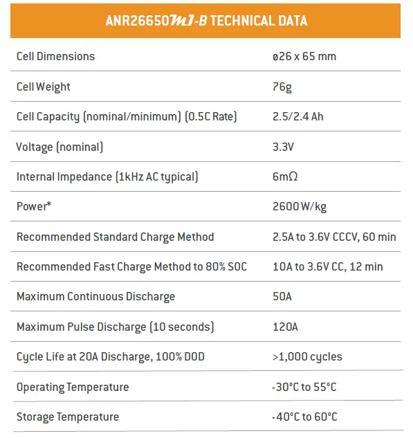
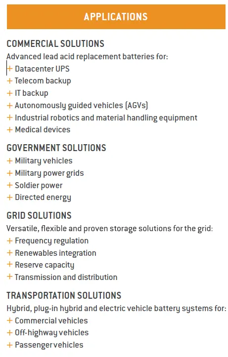
To create a pack of 10 cells in series, cell with following parameter is used.
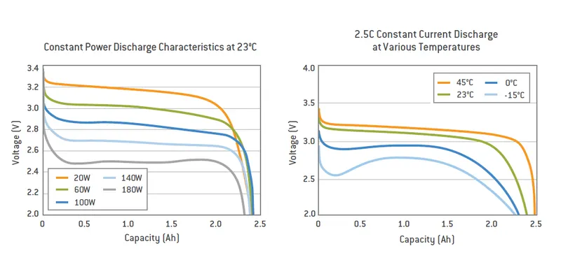
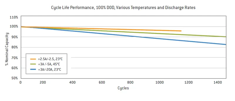
The graphs associated with the cell are as follows:-
Simulink model
The model consists of 6 major subsystem blocks which are connected to each other to complete the circuit.
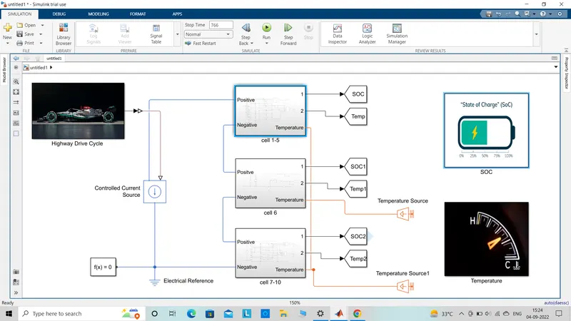
a) Highway drive cycle subsystem block- This susbsytem contains the signal builder and a output of which is connected to the output port. The model consists of a table based battery with electrical and thermal connections as shown below. Signal builder is used to input the data and give the signal to controlled signal source. Signal builder is set with HWFET highway drive cycle to test the battery performance.
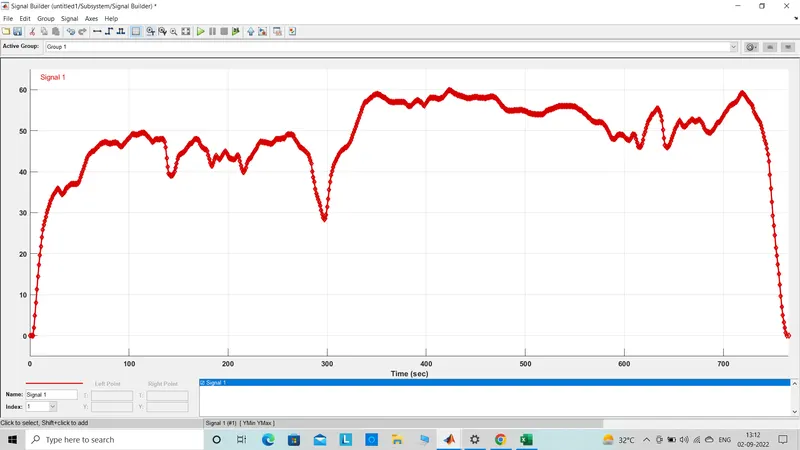
The output of which is connected to a controlled current source block. This block gets one input from highway drive cycle block and other one from the +ve terminal of the cells in series. The output is connected to -ve terminal of the cells in series.
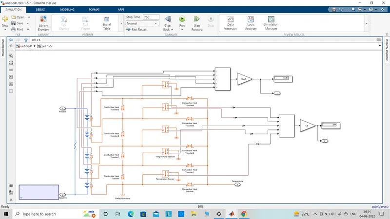
b) Cell 1-5 block- The block contains cells from 1 to 5. Inside the block the whole connection is done. The cells have the connected in series and in between +ve terminal and -ve terminal. The battery used table based and is constructed with soc and temperature outlet port. This completes the electrical connection. Thermal connection is done bt taking temperature source, convection and conduction hat transfer,temperature sensor. Convection heat transfer is used to transfer heat from source to the cells. The conduction heat transfer is used to short the path in between 2 cell.
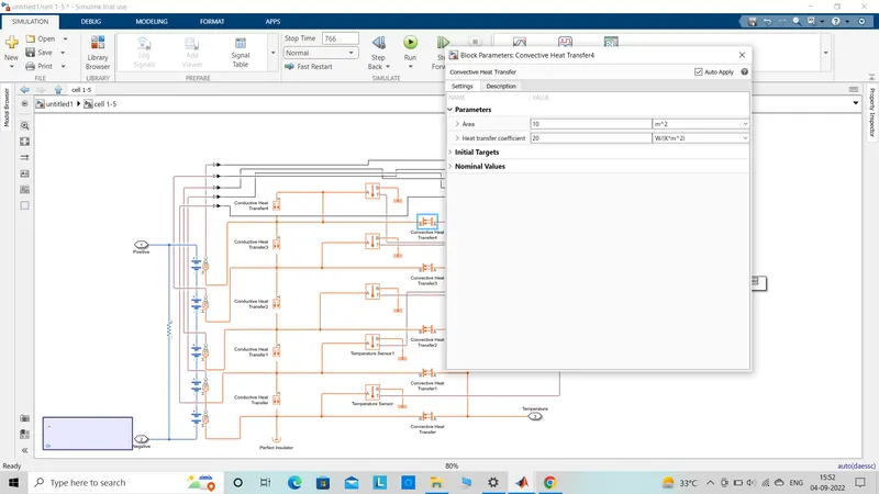
The convection transfer block present in 1-5 cell block and 7-10 cell block is set to contact area of 10m^2.
The output is added and average of soc and temperature of the 5 cell are calculated. Gain block is used to do the same and scope gives the final graph of the temperature variation.
c)Cell 6th block- This block has the primary setup of only 1 cell. Temperature and electrical connections are made and the observation is studied by the display and scope blocks.
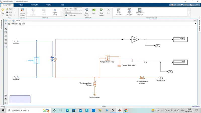
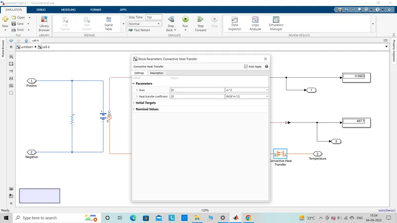
The contact area setting inside the convection heat transfer block is set to 50m^2.
d) Cell 7-10 block - This block is similar to the 1-5 cell block with only difference is the cell numbers i.e 4. The average of soc and temperature is taken for 4 cells.
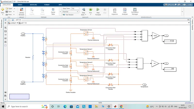
All the 10 cell blocks containing the cells are inputed the temperature value by the temperature source. 1-5 cell and 7-10 cell recieve the same temperture input while cell 6 block receives a another temperature input. All the outputs are connected to a goto block.
The soc block contains the other goto block of the same pair. There are 3 such pairs which are all connected to a scope.
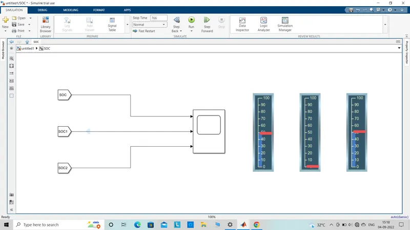
Temperature subsystem block contains all the other unit of the goto pair. There 3 such pair which are connected to the scope.
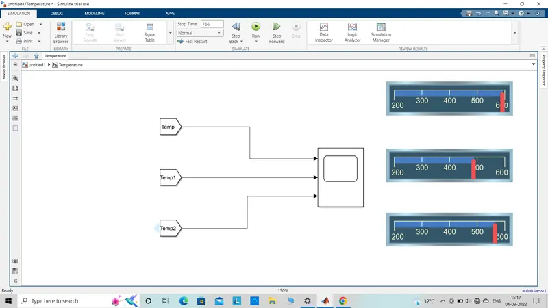
All the goto blocks are connected to horizontal and vertical gauge blocks.
Temperature source of 1-5 cell block and 7-10 cell block is set to 298K
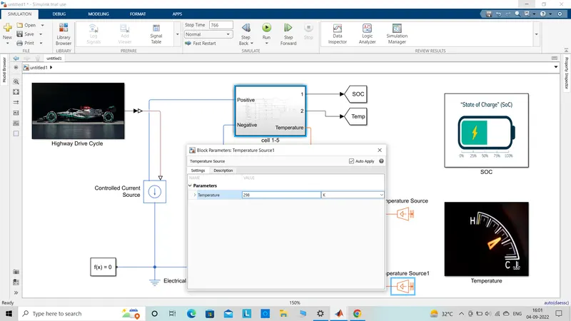
Temperature source of 6th cell block is set to 306K
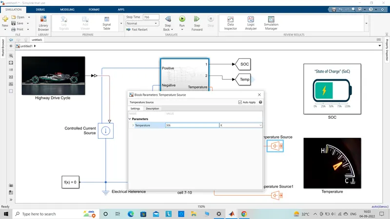
The model is completed by connecting solver configuration and electrical reference. Total simulation time of the model is the total highway drive cycle time which is given as 766 secs.
Output graph
Soc graph of the 2 blocks connecting cells.
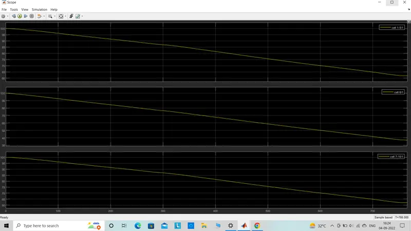
Soc graph obtained states that cell 6 which has the higher amount of contact area has reduced below 40% soc. The remaining 2 blocks have lower contact area in convection heat transfer and it is observed to have reduced to 63% soc.
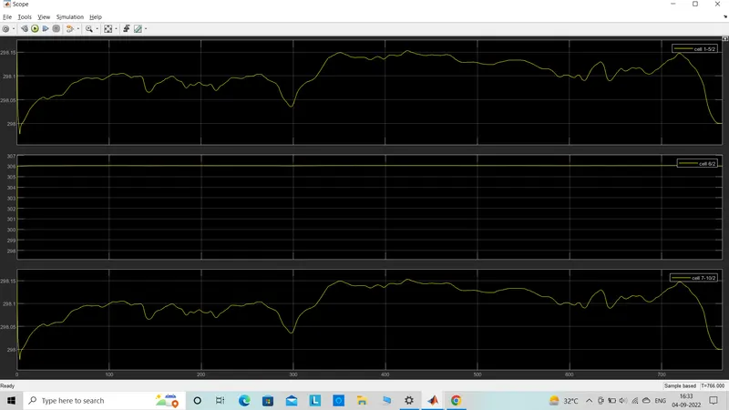
Temperature graph states that if the contact area is increased then the temperature of the same cell is high when compared to the other cells.