Project 2 Thermal modeling of battery pack
AIM:- The aim of the project is to simulate the thermal effects and compare life cycle performance at various temperatures, charge & discharge rates using MATLAB.
PROCEDURE:- In order to do the simulation we need the simulink model for 10 cell that are connected in series as required by the question, for that following blocks are used for building the model
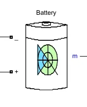
Battery:- The Battery block implements a generic dynamic model that represents most popular types of rechargeable batteries. For this model enable the temperature effects and aging effects options. So cell nominal voltage is 7.2 V, capacity 5.4 Ah, initial SOC 0%, in aging section aging model aging sample time is 1000 sec, aging characteristic at cell ambient temperature of cell 25°C .
Signal generator:- The Signal Generator block can produce one of four different waveforms: sine, square, sawtooth and random. We can express signal parameters in hertz or radians per second. For this model we used square waveform with Discharge & charge Current as amplitude and 1/(3600) Hz frequency. This signal is provided to the current controlled source.
Constant(Ambient Temp):- A constant is used to provide the ambient temperature to the cells.

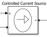
Controlled Current Source:- The Controlled Current Source block converts the Simulink input signal into an equivalent current source. The generated current is driven by the input signal of the block. The positive current direction is as shown by the arrow in the block icon. We can initialize the Controlled Current Source block with a specific AC or DC current.
Voltage Measurement:- The voltage measurement block is used to measure the terminal voltage of the battery pack.
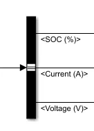
Bus Selector:- Bus selector id used to take 1 input & provide the multiple output that were combined before.
PowerGui:- The powergui solver is used to choose the corrent simulink solver for the model
Final Model:-
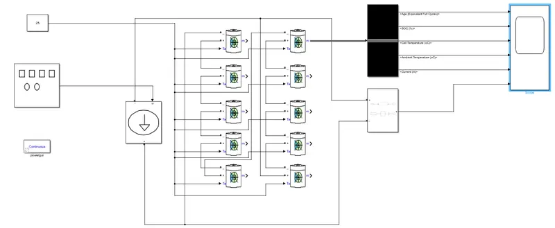
The model is given input by the signal builder(square wave) & a constant for ambient temperature to the battery pack, a Voltage measuring instrument is used to measur the terminal voltage of the battery pack, the bus selector is used to provide the signal to the Scope.
RESULT ANALYSIS:- The Simulation have been done for 2 Cases
1- Variable temperature & Constant charge & discharge current, to show battery pack life thermal performance for various temperature ranges
2- Constant temprature & Variable charge & discharge current, to show battery pack life performance for various charge & discharge rates
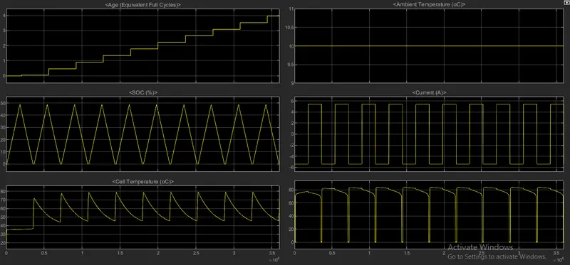
Case 1(a)
Temprature 10C, Current 5.4A:- In this case we can see the fluctuation in the temperature of the battery pack due to significant difference between ambient temperature and cell temperature, which have adverse effect on the battery life & SOC
Case 1(b)
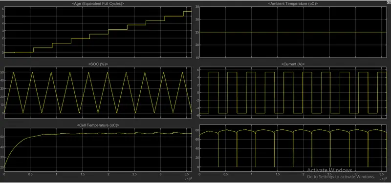
Temprature 25C, Current 5.4A:- In this case we can observe the cell temperature at starting it gradually increases and settles at 52.5°C and fluctuates within the 52-53°C. When the battery starts charging, temperature starts increasing upto 53°C and when battery starts discharging, temperature starts reducing upto 52°C, as the temperature difference between ambient temperature and cell temperature is minimum
Case 1(c)
Temprature 45C, Current 5.4A:- In this case we change the ambient temperature to 45°C and charge-discharge C-rate keeps the same i.e. 1C. Due to this reason battery pack SOC and voltage is same but this ambient temperature adverse effect replicates in the age of cycle and of course cell temperature also increases. In two hours the battery uses 1 life cycle but at the same time the age of the battery increases approximately 1.5 instead of 1. After completing the 5 life cycle, the battery age is approximately 7.5. And the cell temperature reaches 75°C.

Case 2(a)
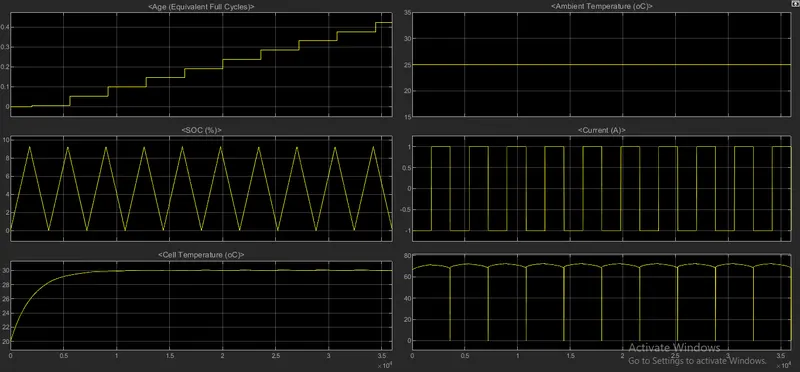
Temprature 25C, Current 1A:- In this case we changed the charge-discharge current to 1A i.e. 0.18C rate. After completing the 2 hours of simulation, the age of the battery only increases to 0.1. In the battery pack voltage plot voltage spike amplitude is increased as compared to the case 4. Because the C-rate is very small, the cell temperature is 49°C and it is stable and does not fluctuate widely.
Case 2(b)
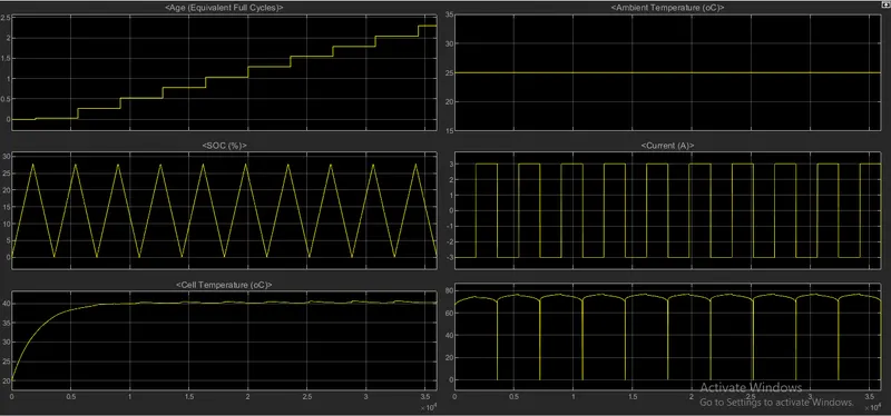
Temprature 25C, Current 3A:- In this case the charge-discharge current is reduced to 3A i.e. 0.56C rate.the voltage of battery pack plots also changes and after completing the two hours simulation, the age of the battery is below 0.5 and reaching one age of the battery requires more than 5 hours. In this case charge-discharge rate decreases, therefore cell temperature is also less i.e. 49°C.
Case 2(c)
Temprature 25C, Current 5.4A:- In this case the, cells charge-discharge at 1C rate. Therefore the battery pack SOC completely reduces or packs full charge within the 1 hour. Thus In 2 hours the battery pack completed 1 life cycle and if we see in the Age plote, the age of the battery pack increases by exactly 1 age
From this different case study we can conclude that:
- When the ambient temperature increases then obviously cell temperature is increased also this ambient temperature adverse effect reflects on the age of the battery pack and vice versa.
- Similarly when we decrease C rate then shows the favorable and unfavorable effects on the age, SOC, temperature and voltage of the battery pack.
- The age of the battery increases slowly, SOC not able to charge or discharge completely, cell temperature is less and in the voltages spikes are present.
Simulink File
https://drive.google.com/file/d/1wrqJoDCqW5KDPUW8h0e6MUPvU0E0e6sP/view?usp=sharing