Project 2 Thermal modeling of battery pack
LITHITUM ION BATTERY
Lithium-ion battery A lithium-ion battery or Li-ion battery is a type of rechargeable battery. Lithium-ion batteries are commonly used for portable electronics and electric vehicles and are growing in popularity for military and aerospace applications. In the batteries, lithium ions move from the negative electrode through an electrolyte to the positive electrode durinc discharge, and back when charging. Li-ion batteries use an intercalated lithium compound as the material at the positive electrode and typically graphite at the negative electrode. The batteries have a high energy density, no memory effect (other than LFP cells), and low self-discharge. They can however be a safety hazard since they contain flammable electrolytes, and if damaged or incorrectly charged can lead to explosions and fires. Samsung was forced to recall Galaxy Note 7 handsets following lithium-ion fires, and there have been several incidents involving batteries on Boeing 787s.
Main Block model working Explanation: Generic battery
Implements a generic battery model for most popular battery types. Temperature and aging (due to cycling) effects can be specified for Lithium-Ion battery type.
Controlled current source:
Converts the Simulink input signal into an equivalent current source. The generated current is driven by the input signal of the block.
Square wave generator:
It generates the frequency wave with respect to time and amplitude.
Simulink model
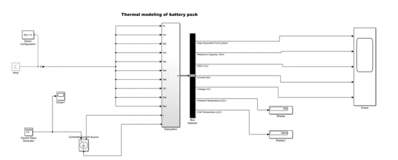
Model Explanation:
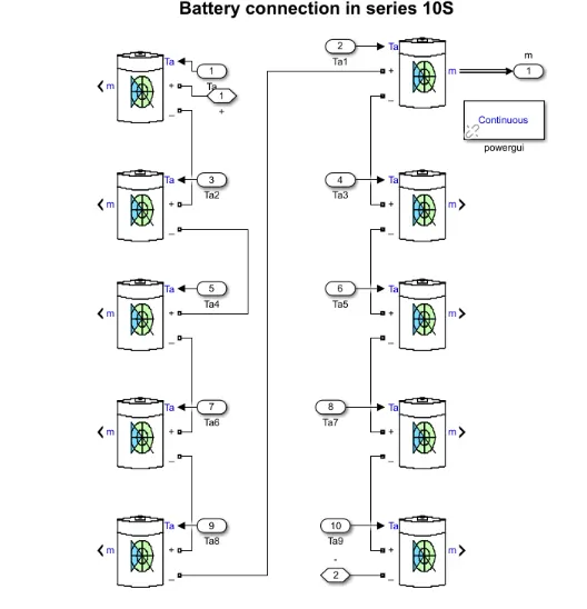
- First, I can use the generic battery and select the battery type of lithium-ion I'll try to connect the l0 batteries as a series connection model for the series connection model to connect the positive terminal to the negative and select all blocks and create the subsystem for that.
- When the battery model I can select the temperature and aging option so my battery wants inputs as so, that's why I can connect the PS constant block to the battery temp input, and give the temp for 298k to heat up the battery.
- When the positive and negative terminal of the battery can be connected to the controlled voltage source it's used to control the charge and discharge the current with respect to the demand. here I can use the square wave generator is used for the load condition of the battery.
- For the result analysis, I can use the bus selector can analyze the multiple outputs of SOC%, current, voltage, max capacity, and displayed in scope.
- The display block is used to show the final value temp of the battery pack.
Scope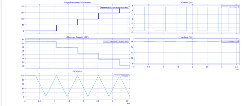
Result Explanation: When the simulation time is run for 3600s*10 cycles at 1 C-rate at the temp at 298 kelvin.
- Plot-1 shows the life cycle of the battery pack which is around 190.
- Plot-2, We can see the current is fluctuating between +5.5 A to -5.5 A which indicates the charging and discharging of the battery.
- Plot-3 shows the max capacity of the battery, As we can see the capacity falls at almost 5.7 A W.R.T during the life cycle.
- Plot-4, Shows the voltage of the battery is around 16 volts as we can notice there is a slight fall for that condition voltage gets discharging.
- Plot-5, Shows the % of SOC initially the battery is fully charged and discharged almost 5%, and again it starts charging up to 100% depending on the given input.
- When the display we can see that the ambient temp we can give is 298 K but the cell temp is 356 which is around 2% increase of ambient temp.
45 days program EV batch 20