Project 2 Thermal modeling of battery pack
Obhective :
To create a model for a 10 cell series lithium ion battery model, simulate the thermal effects and compare life cycle performance at various temperatures, charge & discharge rates using MATLAB.
The standard rating for batteries is at room temperature 25 degrees C (about 77 F). At approximately -22 degrees F (-30 C), battery Ah capacity drops to 50%. At freezing, capacity is reduced by 20%. Capacity is increased at higher temperatures – at 122 degrees F, battery capacity would be about 12% higher.
Battery capacity (how many amp-hours it can hold) is reduced as temperature goes down, and increased as temperature goes up. This is why your car battery dies on a cold winter morning, even though it worked fine the previous afternoon. If your batteries spend part of the year shivering in the cold, the reduced capacity has to be taken into account when sizing the system batteries.
Internal temperature of a battery
Thermal mass means that because they have so much mass, they will change internal temperature much slower than the surrounding air temperature. A large insulated battery bank may vary as little as 10 degrees over 24 hours internally, even though the air temperature varies from 20 to 70 degrees. For this reason, external (add-on) temperature sensors should be attached to one of the POSITIVE plate terminals, and bundled up a little with some type of insulation on the terminal. The sensor will then read very close to the actual internal battery temperature.
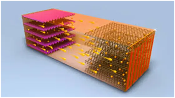
Battery life reduces at higher temperatures
Even though battery capacity at high temperatures is higher, battery life is shortened. Battery capacity is reduced by 50% at -22 degrees F – but battery LIFE increases by about 60%. Battery life is reduced at higher temperatures – for every 15 degrees F over 77, battery life is cut in half. This holds true for ANY type of lead-acid battery, whether sealed, Gel, AGM, industrial or whatever. This is actually not as bad as it seems, as the battery will tend to average out the good and bad times.
An EV battery works best at temperatures between 20 and 25°C.
Outside temperatures affect electric car batteries. In the winter months when temperatures fall below 20 degrees, electric car batteries take a major hit. A study by AAA found that if you use your electric car's heater while driving in cold temperatures, your range can be temporarily cut by as much as 41 percent.
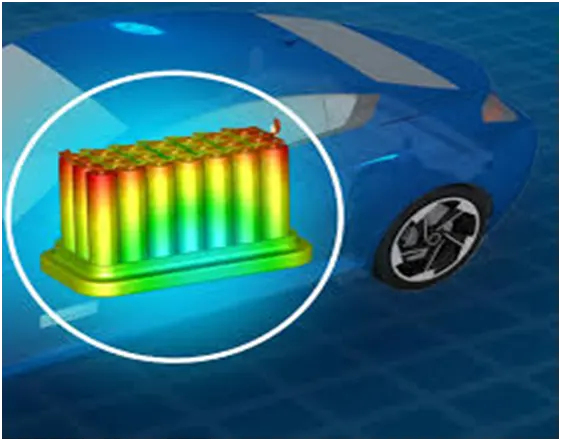
Temperature is known to have a big influence on the rate of Li battery degradation. One of the main reasons that it is so critical is because temperature affects the rate and efficiency of chemical reactions inside a battery. Higher temperatures, (or higher voltages - but that’s another article), generally lead to faster reactions. This often means that the “unwanted” chemical reactions that make batteries degrade happen faster at higher temps.
SIMULINK Modeling of the 10 cell series lithium ion battery :
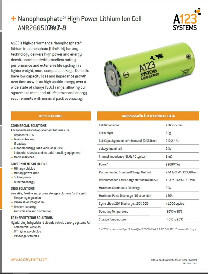
* here the battery considered is ANR26650m1-B model and the battery parameters are also considered accordingly
* now lets get into the SIMULINK page and design the model according to the given condition
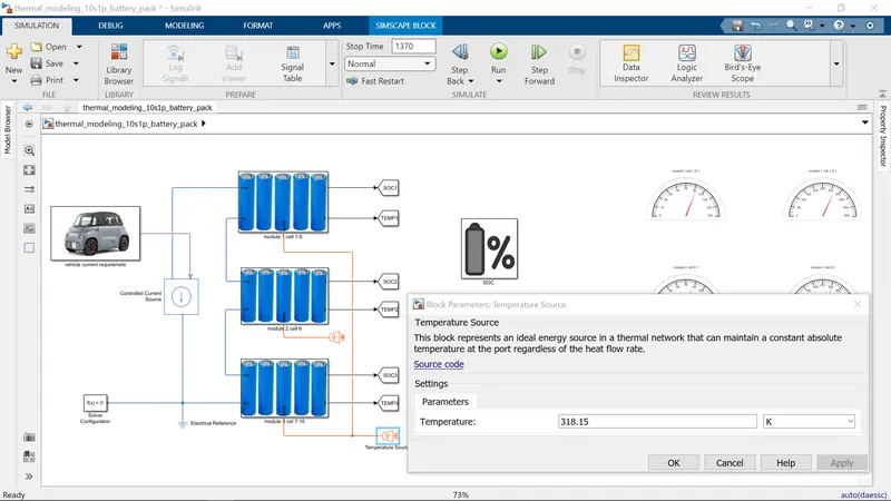
below i am attaching the model which is created in SIMULINK acording to the specifications
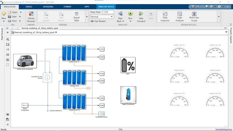
* here i had tahen a simple subsystem as a vehicle current requirement as the input to the controlled current source and the below image
* here we can see the data adding to the signal builder from the drive cycle
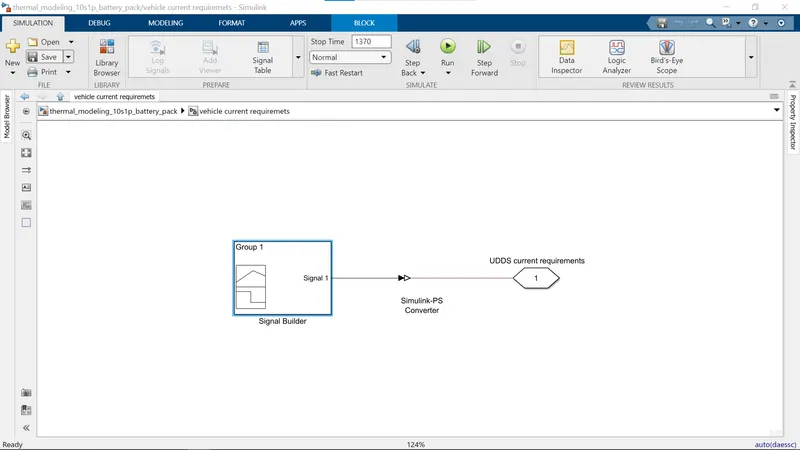
* if we observe the signal builder block is connected to the outport of the UDDS current requirements as shown in the above image
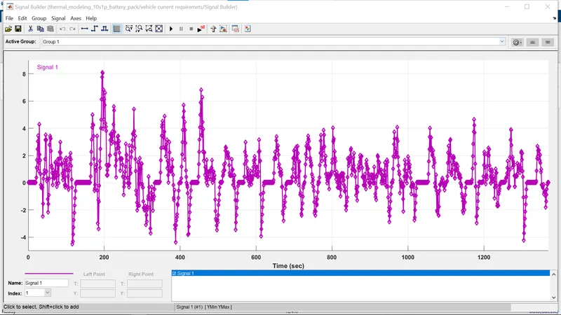
* as we observe the above picture the UDDS cycle data is given as input to the model and the signal is created in the signal builder according to the data in the UDDS file
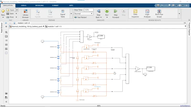
* if we observe the below image the subsystem is created with a five battery pack and connected with five temparature sensore and convective heat transfer and conductive heat transfer blocks and the whole thing is connected to ADD blocks and from it to gain. by here the first battery module modeling is completed
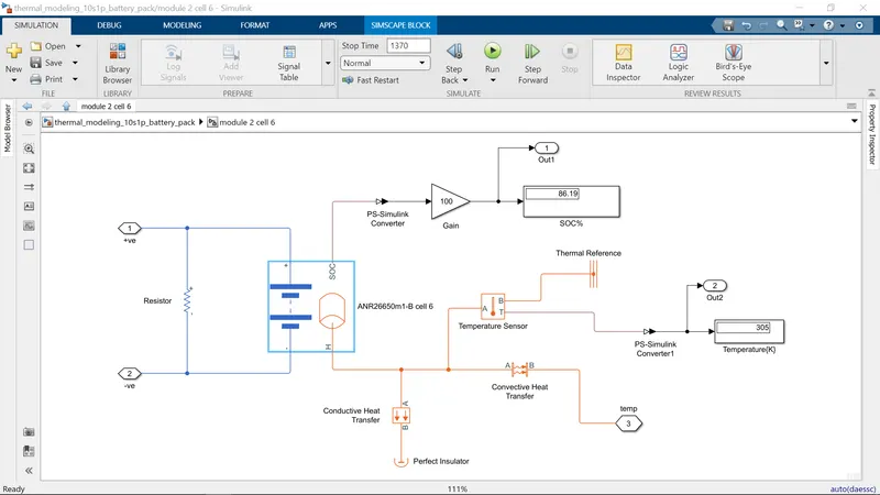
* here if we observe the model the resistor is connected in the first of in between the inport 1 and 2 and remaining connections as ususal as the connections of the five battery pack but only the change in this model is only one battery is connected to find the battery status of unhealty battery.
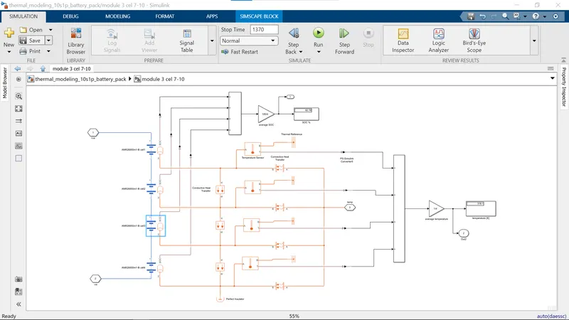
* so if we observe this model the number of batteries taken are four cells and rest of the connections are same as the remaining battery modules and make sure to connect the perferct insulator block at the bottom of the model in each module to avoid the errors
* so, by here the 10 battery cells are connected as 10S1P and the sequence is 5 battery module, single battery module and 4 battery module
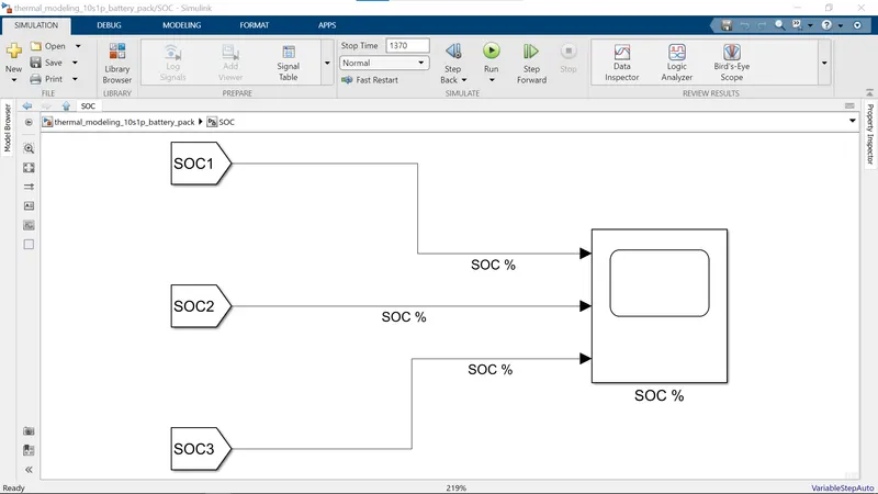
* if we observe the model the output ports of the all battery module subsystem are connected to the GOTO block so the SOC ports are also connected to the GOTO block so the new subsystem is taken and the FROM block is taken and connected with the GOTO block and the outputs are connected to the scope
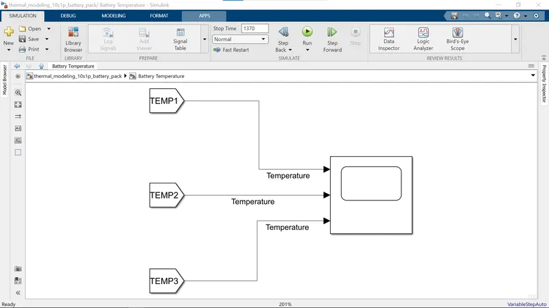
* as the temparature output ports are also connected to the GOTO ports the new subsystem is taken and in that the FROM blocks are taken and are connected with GOTO ports of temparature of the battery modules and the outputs are connected to the scopes
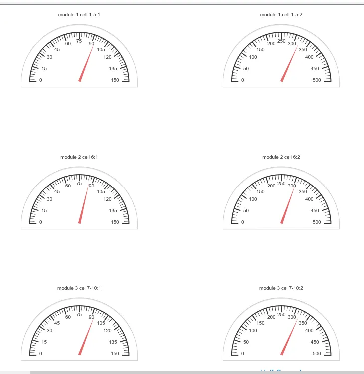
* and now lets perform this test at 250c and run the simulation and lets see the results and we can also see the SOC and temparature values on the gauge block which is provided at the right side of the model and those gauges are connected to SOC signals and Temparature signals
* and here the input temparature value is given as kelvin value (298)
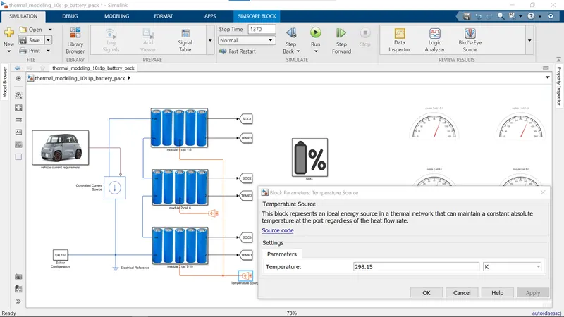
* gauge values of SOC and Temparature at 298 kelvin teparature

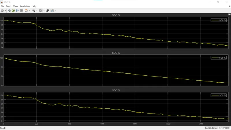
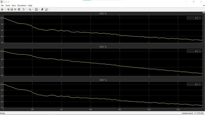
* if we observe the SOC graph outputs the single cell moduile SOC is some clear compare to the five battery module SOC and four battery module SOC because of number of batteris are connected in the module
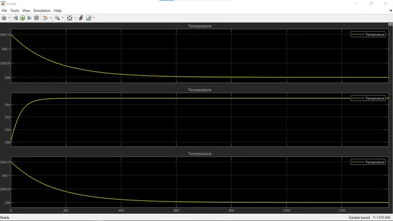
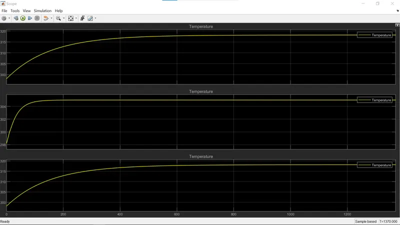
* and if we see the output graph of the Temparature scope the five module battery pack temparature is slightly decreasing and the four cell battery pack module temparature is also gradually decreasing and the temparature of the single cell battery module is increasing because the energy outgoing is shared between the remianing cells in five cell module and four cell module but in single cell the burden is on that cell only so the temparature is increasing
* and now lets perform this test at 450c and run the simulation and lets see the results and we can also see the SOC and temparature values on the gauge block which is provided at the right side of the model and those gauges are connected to SOC signals and Temparature signals
* and here the input temparature value is given as kelvin value (318)
* gauge values of SOC and Temparature at 318 kelvin teparature
* if we observe the SOC graph outputs the single cell moduile SOC is some clear compare to the five battery module SOC and four battery module SOC because of number of batteris are connected in the module
* if we observe the initial temparature of the three modules is at 298k temparature and then the five cell battery moule temparature and thye four cell battery module temparature is more rised to 318k temparature and the single cell temparature value is at 305k temparature because of the adding of 5ohm resistor also.
Note :
below i am attaching the model SIMULINK (.SLX) file for the reference. please consider it.
Thank you ;
B. V. N. SANDEEP.