Project 2 Thermal modeling of battery pack
AIM:
For a 10 cell series lithium ion battery model, simulate the thermal effects and compare life cycle performance at various temperatures, charge & discharge rates using MATLAB.
Introduction:
EVs, HEVs and PHEVs are powerd by lithium ion cells which are fitted together in a battery pack with particular series and parallel arrangements. The Lithium-ion batteries are widely used as energy sources in different hybrid and electric vehicle, however, the operation characteristics of the battery in such vehicle are strongly dependent on the operation temperature and therefore, with purpose to improve these characteristics a good thermal control system should be utilized.
During the design stage of a battery pack, the cells in the pack are tested to simulate their thermal effects and life cycle performance under various conditions. These conditions are real life situations that the battery pack may operate at when in use in a vehicle by a user and these tests are performed to observe how the cells behave.
Lithium-Ion Battery Pack with Fault is to simulate a battery pack consisting of multiple series-connected cells in an efficient manner. It also shows how a fault can be introduced into one of the cells to see the impact on battery performance and cell temperatures.
SIMULINK MODEL:
For this, we are going to use MATLAB-Simulink Model, instead of using direct battery model we are using equivalent circuit 1RC model for Lithium Mode. In this we are characterizing Battery model using Capacitor and resistor in parallel. The characteristic equations are made using Lookup table.
The fault model is used a variety of thermal related blocks to modify and measure the thermal effects of this system. For instance, it uses a temperature source block which allows us to change and set the ambient temperature. It also uses conductive and convective heat transfer blocks to simulate the heat transfer from the ambient temperature to the battery pack as well as the same between the packs. The second and third packs are connected to their own subsystem to measure the temperature across them. This subsystem uses a temperature sensor block and thermal reference block. These temperature readings are sent to from blocks from GOTO Blocks. These readings from the block are fed in to a Mux block which will take these input signals and output them to a scope so we can see the temperatures of the packs
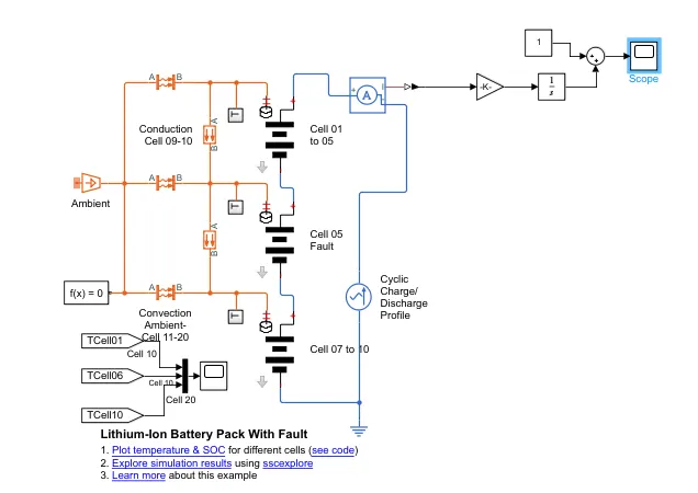
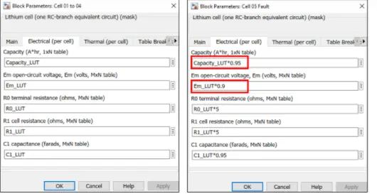
The first and third packs contains 4 and 5 cells respectively whereas the second pack contains 1 cell as the model name suggest, the second pack is designed to be at fault causing undesirable thermal effects from the system by default, the electrical parameters of the normal and faulty packs have the setting for the capacity, open circuit voltage terminal and cell resistance and capacitance as shown below-
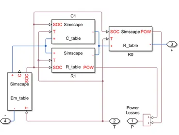
Lithium Cell 1RC Subsystem
This is equivalent circuit of Lithium Iron battery represent by the parallel RC network. As we can see in the model itself there are various block for operation, basically these all blocks are run by the MATLAB script, by which they define the variable.
This block basically consists of capacitance value table which depends on an external physical signal inputs SOC and T. It is assumed that the capacitance value is slowly varying with time, and hence the equation i = C*dv/dt holds.
Resistance value (R) table which depends on an external physical signal inputs SOC and T.
Voltage value (EM) which implements the cell's main branch voltage source, and determines values for capacity (C) and state of charge (SOC). The defining equations depend on cell temperature, T.
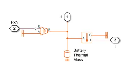
Thermal Model Subsystem
The important block which is inside the thermal model subsystem are:
- Thermal Reference: This block represents a reference point in a thermal network where the temperature is equal to absolute zero.
- Controlled heat flow rate source: This block represents an ideal energy source in a thermal network that can maintain a controlled heat flow rate regardless of the temperature difference. The heat flow rate is set by the physical signal port S. A positive heat flow rate flows from port A to port B.
- Thermal Mass: This block models internal energy storage in a thermal network. The rate of temperature increase is proportional to the heat flow rate into the material and inversely proportional to the mass and specific heat of the material.
- Temperature Sensor: This block measures temperature in a thermal network. There is no heat flow through the sensor. The physical signal port T reports the temperature difference across the sensor. The measurement is positive when the temperature at port A is greater than the temperature at port B
Simulation results:(Faulty cell temp = normal temp)
First ambient temperature is set to 20 C, and temperature of all cell is set to be increment with Time, and at same rate at other.
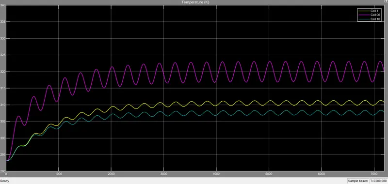
The pink color line represents the cell 6 temp. we can see the increase in temperature and more variation as cell 6 parameters are different than others. The faulty cell temperature rises to 325 Kelvin as other cell temperature is in line with each other.
Heat transfer by conduction
Conduction is basically here Heat Flow rate (Q) and Temperature Difference (T) Vs Time.
From Cell 5 to 6 From Cell 6 to 7
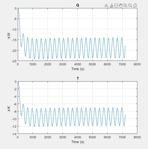
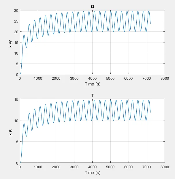
We can see clearly, as cell no. 6 is faulty, the heat is transfer by conduction to neighboring cell as it have more heat. The positive & negative temperature represent the direction o heat transfer
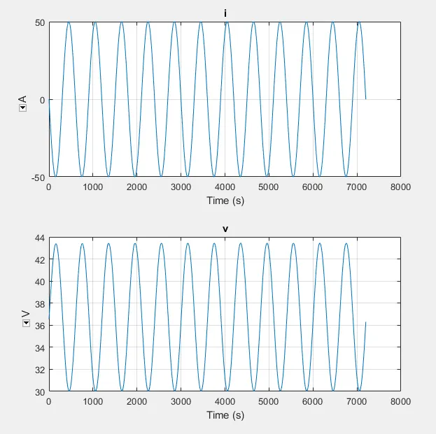
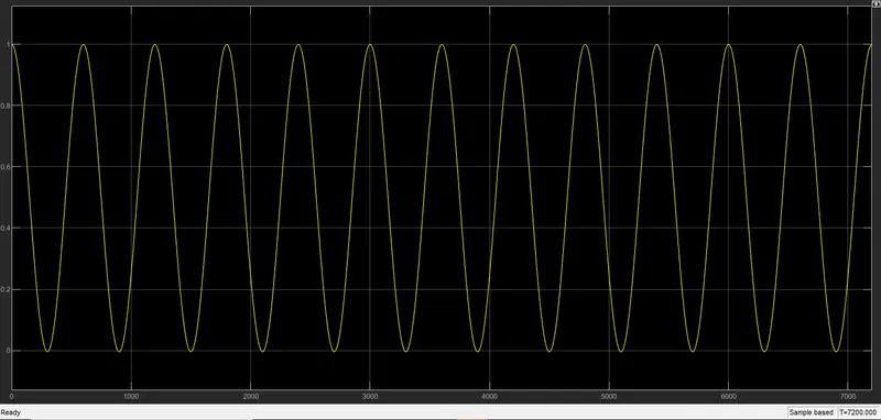
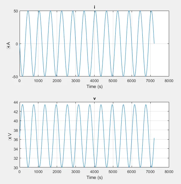
Voltage and Current of Cyclic Charger:
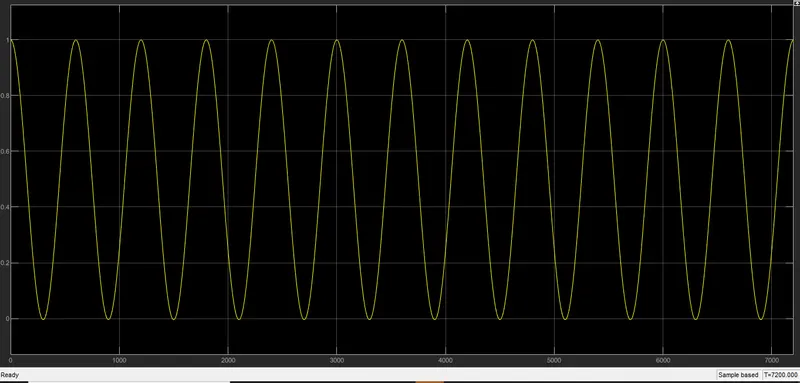
SOC Calculation:
Simulation results:(Faulty cell temp > normal temp)
Ambient temperature is set to 20 C Normal cell temp= 293k, Faulty cell temp=353
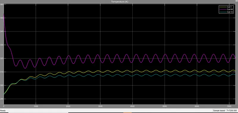
The initial temperature we set to the 353 K and gradualy decreases as heat of faulty cell is transfer to neighboring cell.
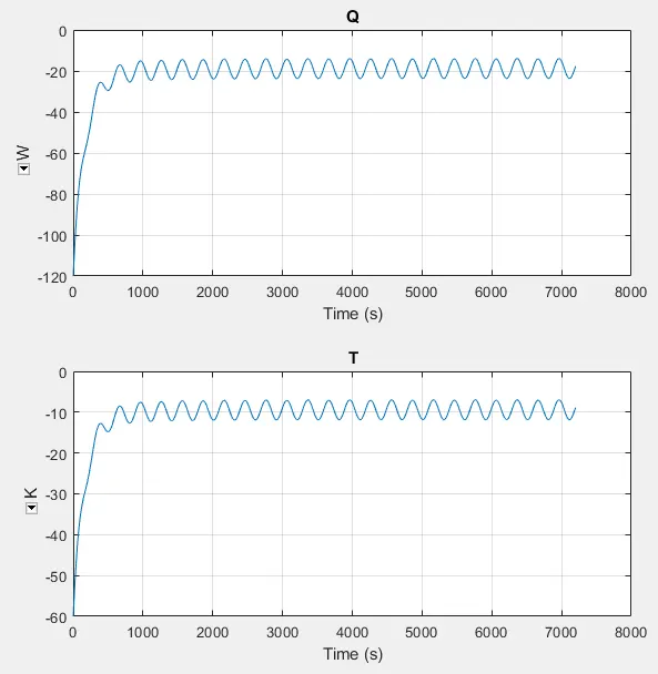
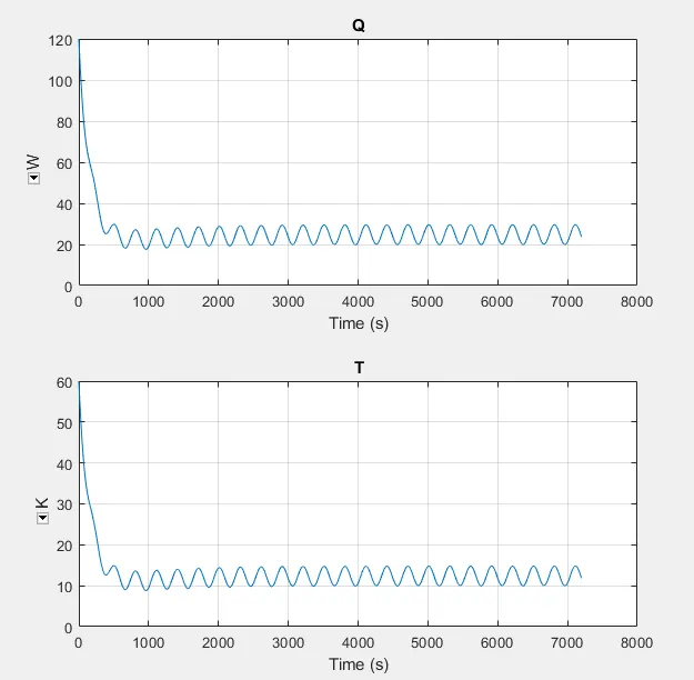
Heat transfer by conduction
Conduction is basically here Heat Flow rate (Q) and Temperature Difference (T) Vs Time.
Voltage and Current of Cyclic Charger:
SOC Calculation:
Conclusion:
- Based on different temperature we will see changes in conduction and convection.
- As I set fault in cell-5 and we can see that there is lots of fluctuation and temperature rise in cell-5 as compared with other cells connected in series.
- SOC for all different temperature are same, there is no changes in SOC.