Project 2 - MODELLING, ANALYSIS & DESIGN OF COMPOSITE STUCTURES IN COMFLOR & ETABS
ETABS
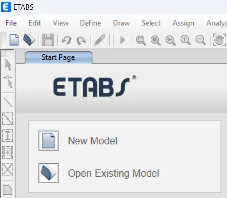
Initially,we open the software where we then continue with the option of New Model.
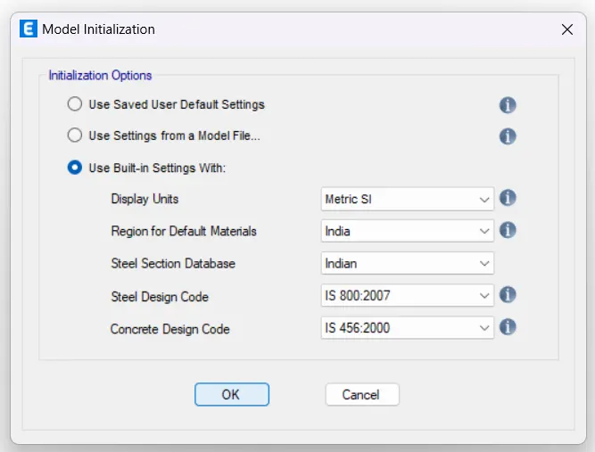
We then initialize the model in the Model Intialization Tab by providing the relevant details.
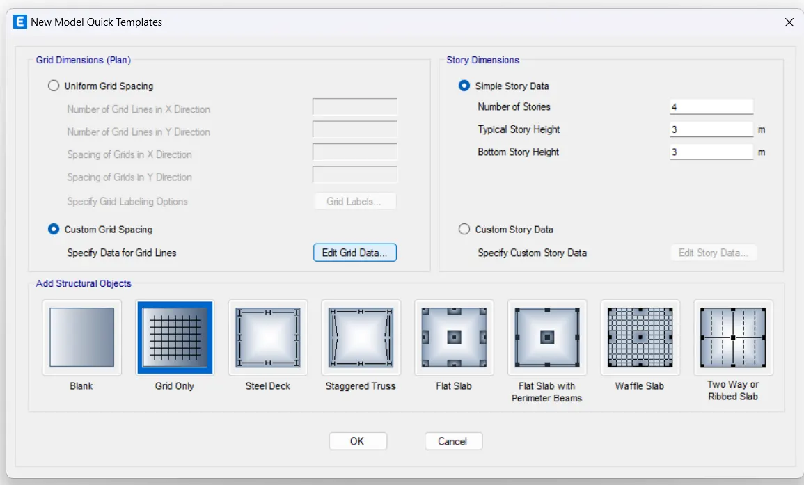
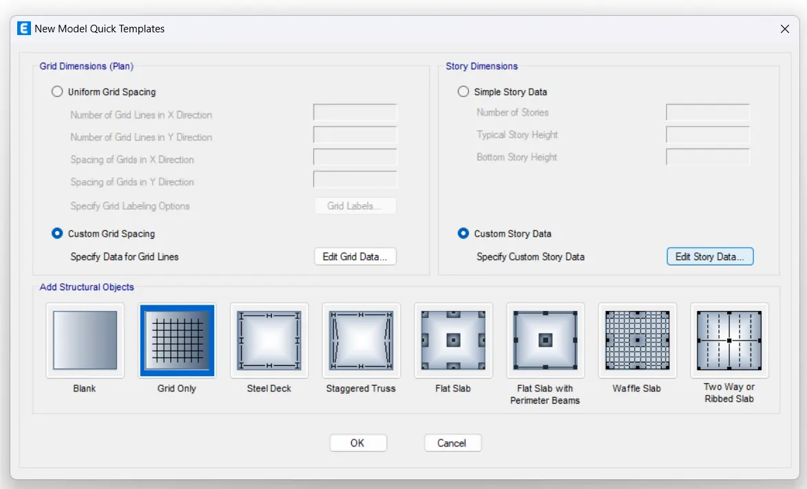
We then edit the default grid data in New Model Quick Template Tab>Edit Grid Data...
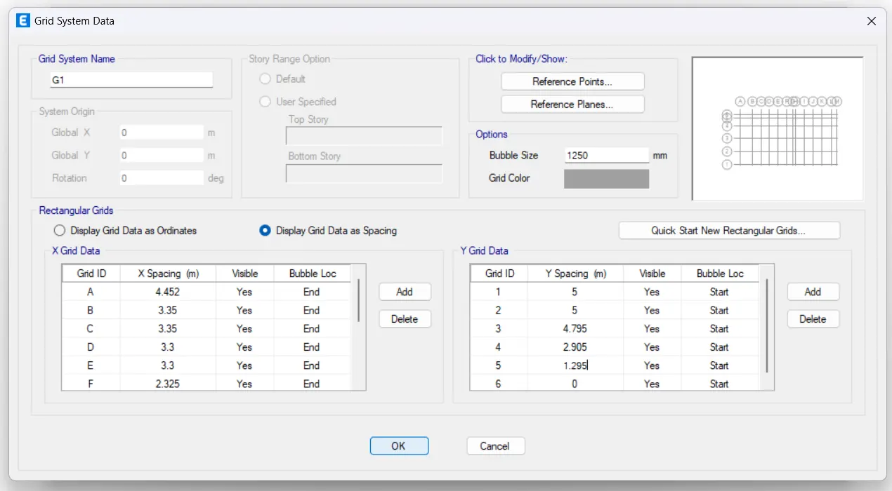
We then provide the relevant spacings to form the grids as required.
In the similar manner,we even form the stories.
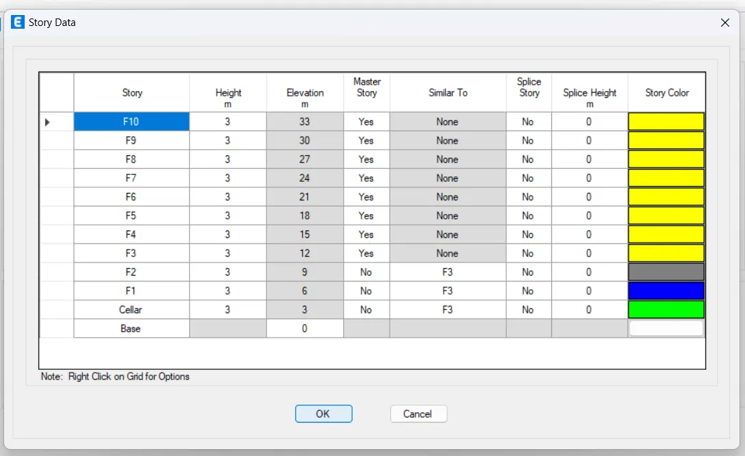
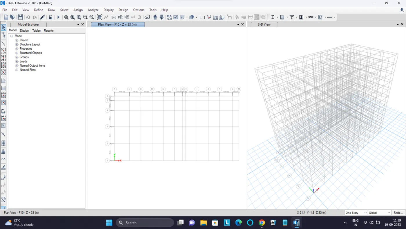
After the provision of the relevant grid and storey data,we can find the 3D model.
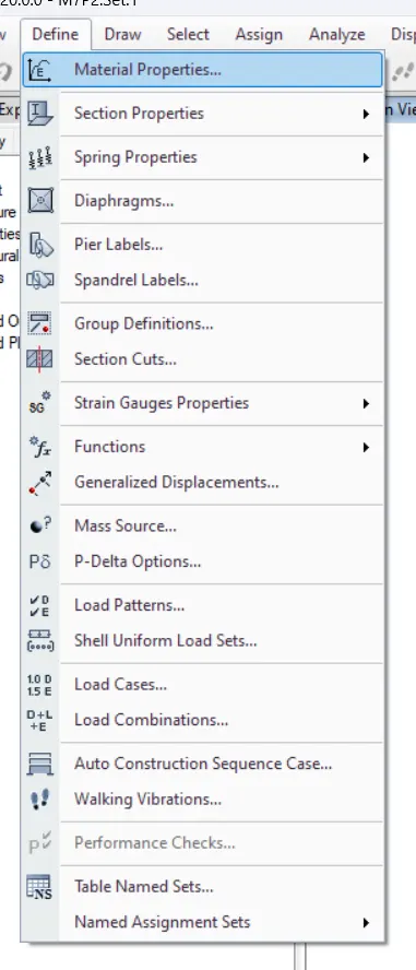
Then,we continue with the definition of the materials.Then we go to Define Tab>Material Properties...
We then continue with the option of Add New Material... in the Define Materials Tab.
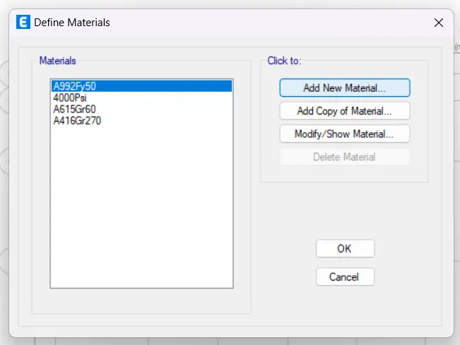
We then add the require materials.
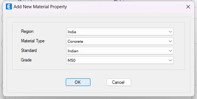
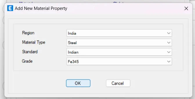
Where this time we add Fe345 Steel along with M50 Concrete.We then continue with the addition of the sections to be used as members.So,we go to Define Tab>Section Properties>Frame Sections...
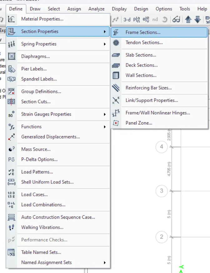
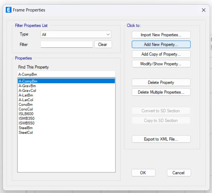
Then in the Frame Properties Tab,we go with Add New Property...
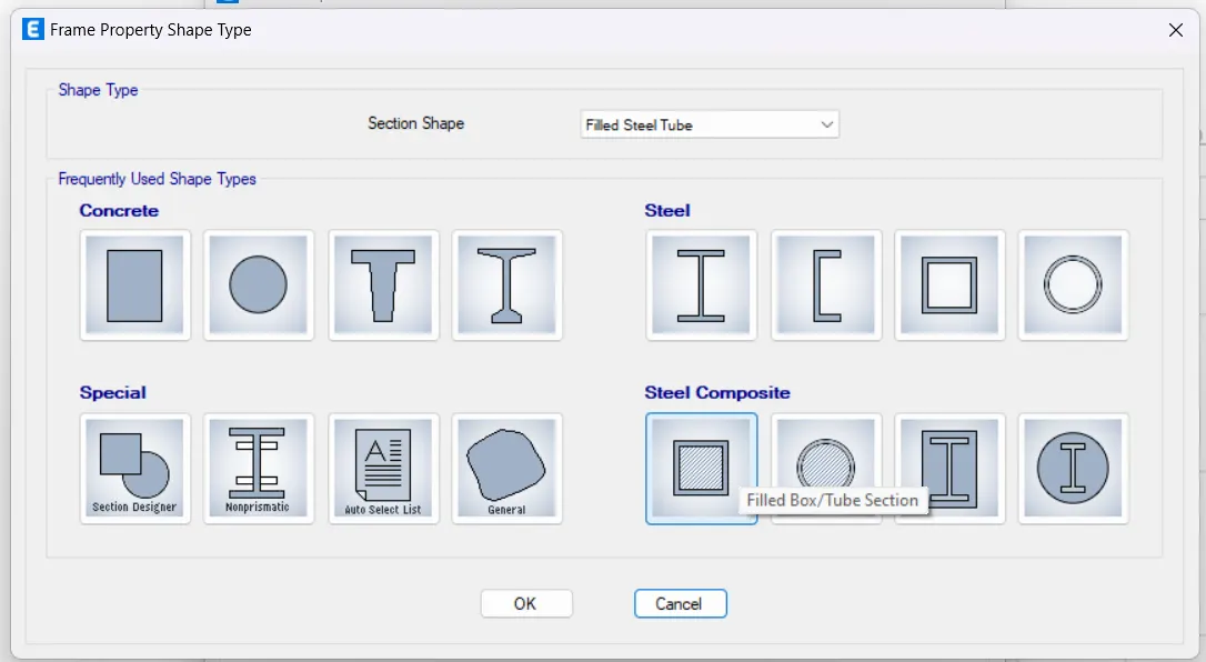
And we select the require shape in Frame Property Shape Type Tab.
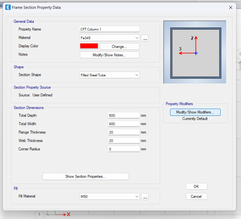
Where we select the Filled Tube/Tube Section and then we provide the other require data in the Frame Section Property Data Tab.
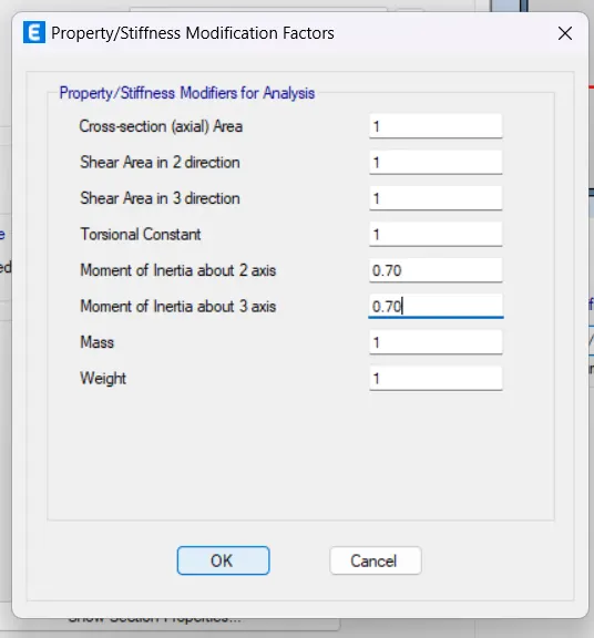
As the above member will be a column,we provide the values for Moment of Inertia about 2 axis and Moment of Inertia about 3 axis as 0.70.
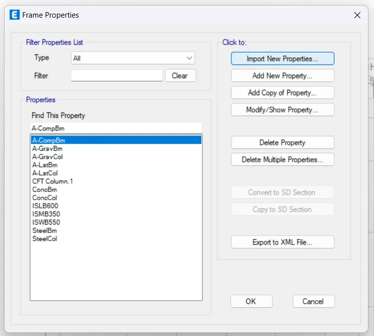
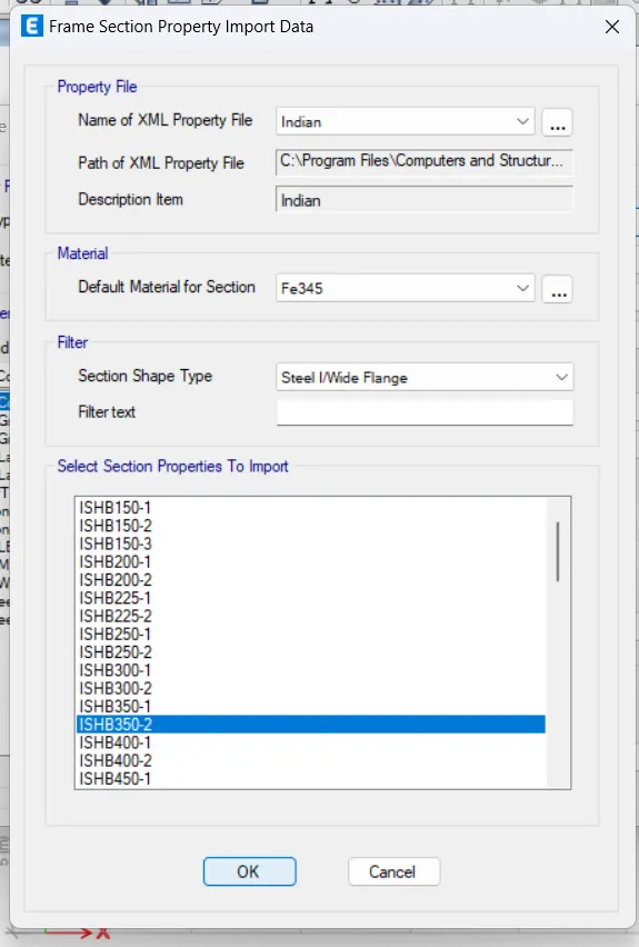
Now,we continue with the creation of a section for the beam.Actually,we have to create a composite beam but due to unavailability of the composite members for the beam,we just go with the normal I section which will be placed as a beam.So,we have to import the I sections as they will be unavailable for the normal use.So,wuse the option of Import New Properties... in Frame Properties Tab.
And give the required data in Frame Section Property Import Data Tab.
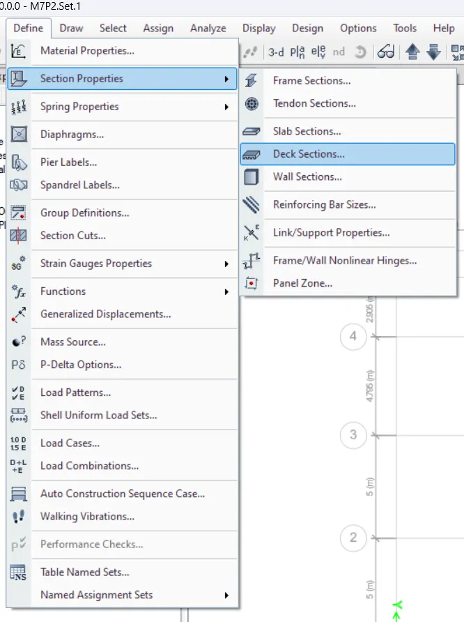
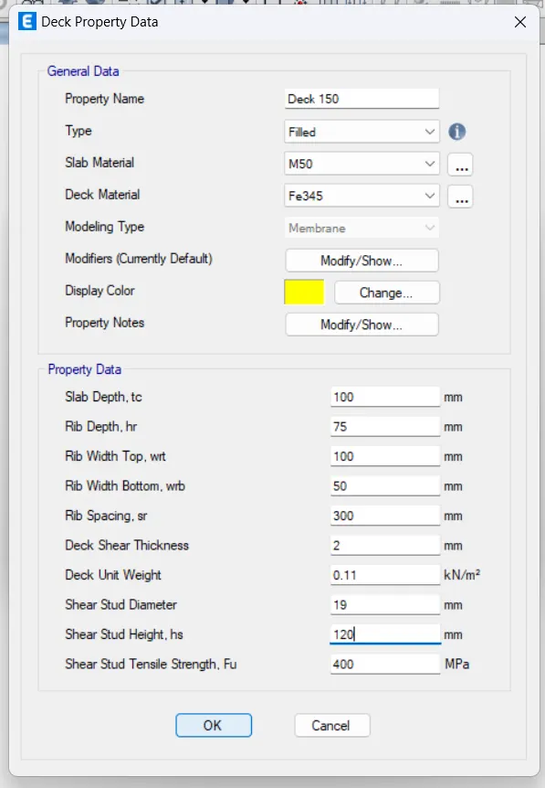
Similarily,we even add a deck slab section for this model.
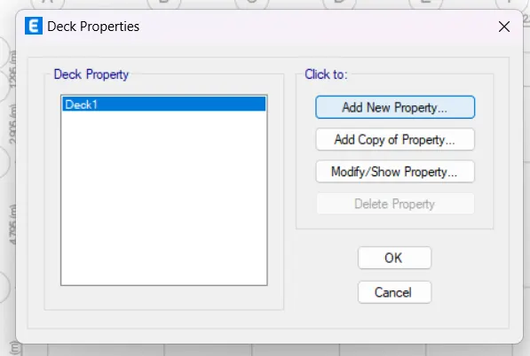
Where give the details of the steel deck too.
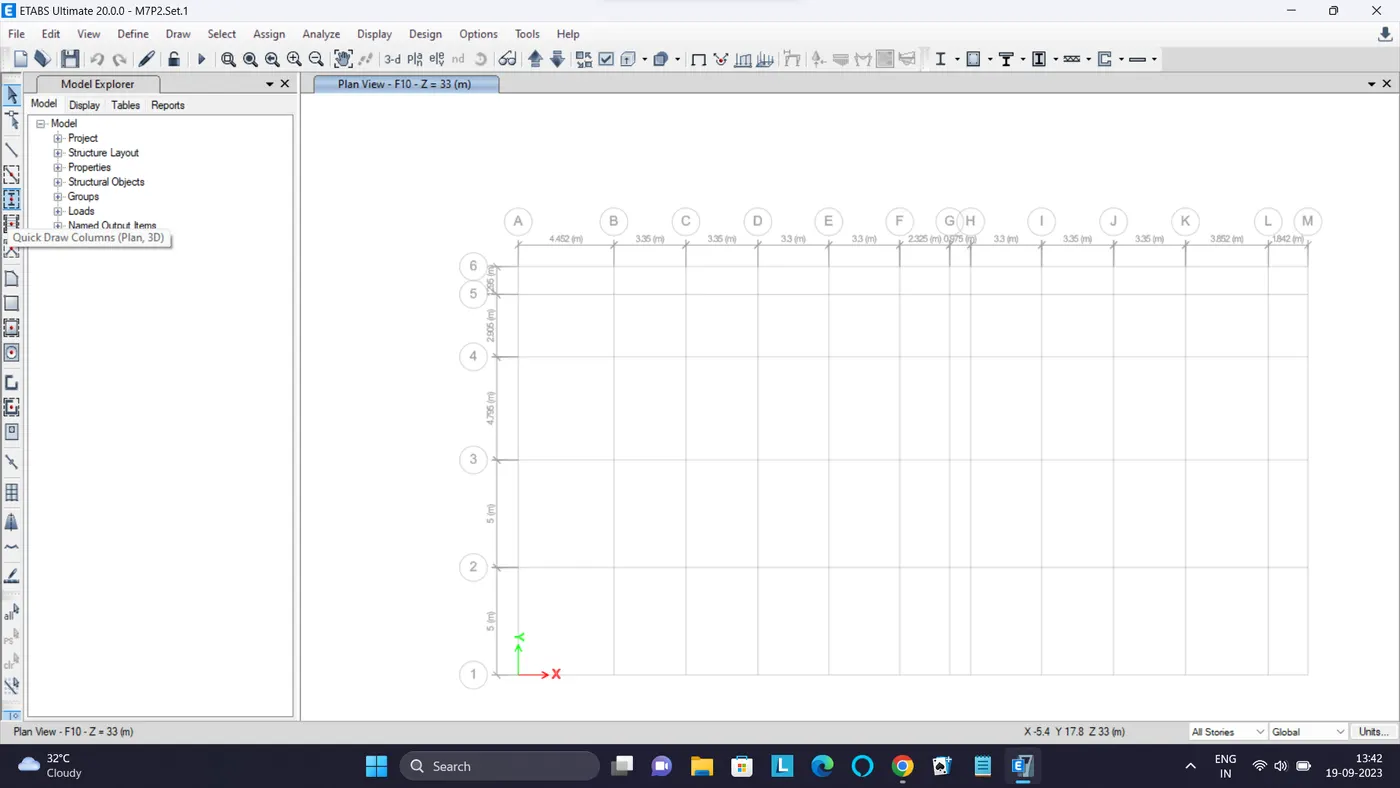
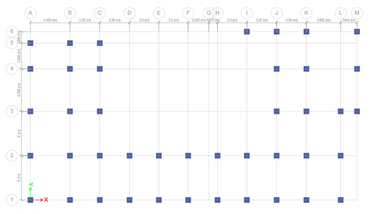
With this,we complete the creation of materials as well as the sections which are to be used for the model.Then using the option of Quick Draw Column,we place the columns in All Stories mode.
Where we create the shear wall sections to be used around the lift core and stair way.
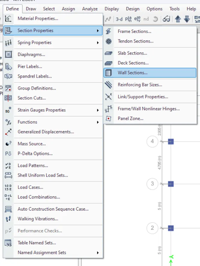
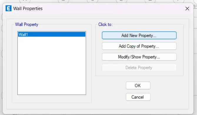
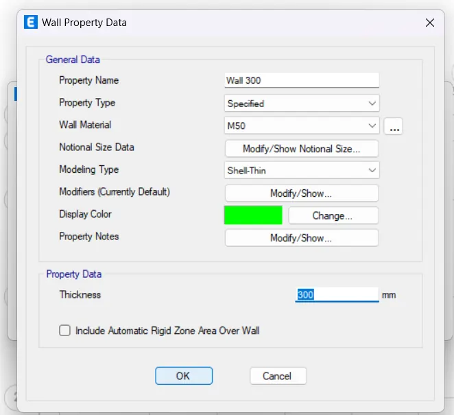
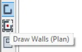
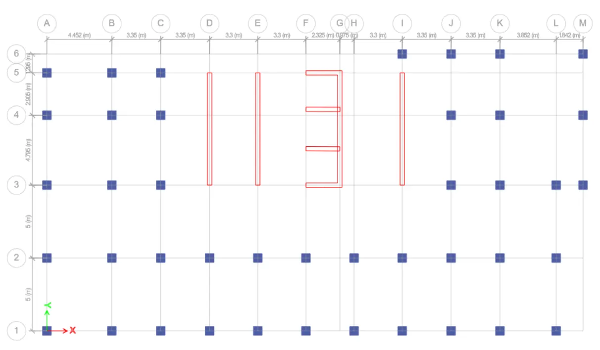
So,after the creation of the shear walls,we place them in the model.
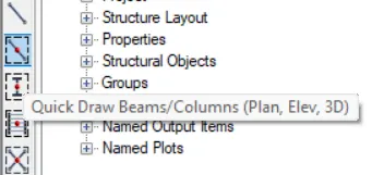
We then place the primary beams using the option of Quick Draw Beams/Columns and place the beams at required places.
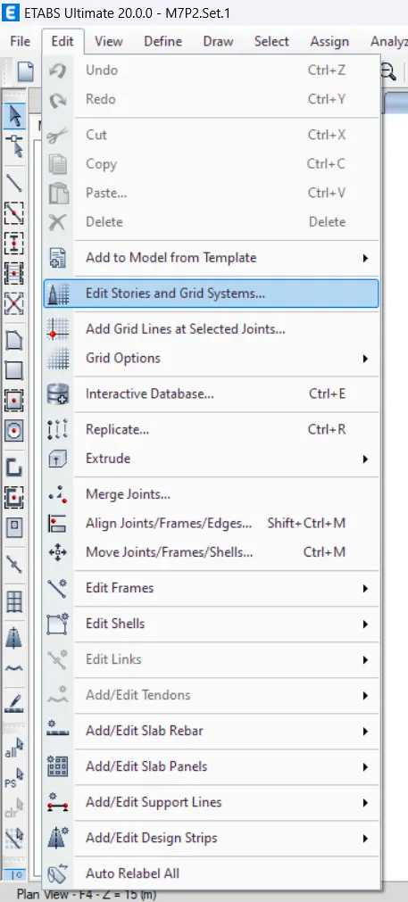
Now,we have to place the secondary beams where so as to make the placing easy,we edit the grid system.So,we go to Edit Tab>Edit Stories and Grid Systems...
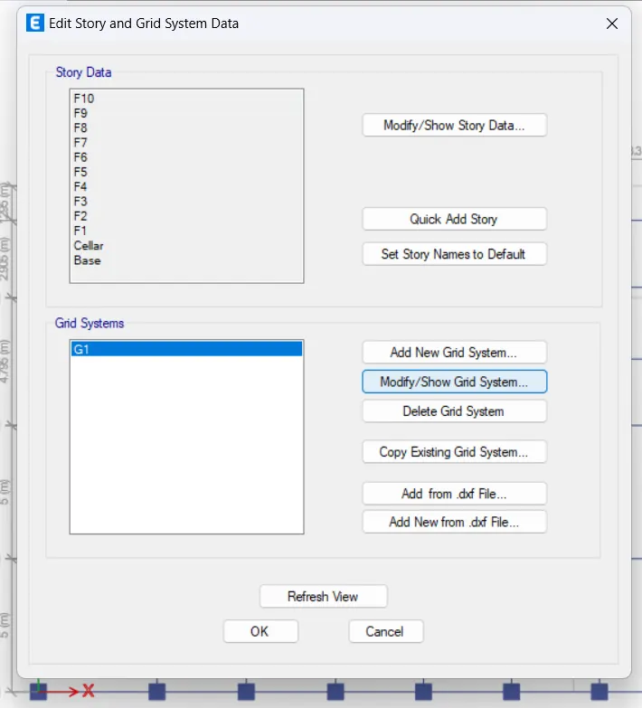
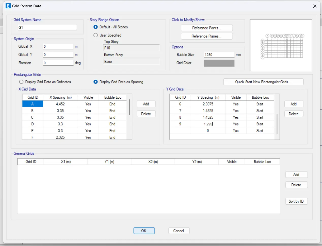
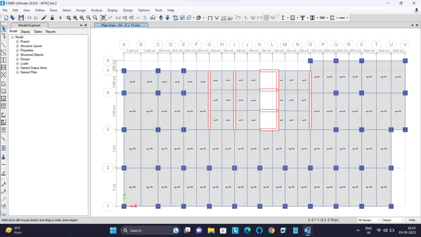
So,we change the spacings in one direction only.
And then ultimately,we place the secondary beams but we use the same primary beam section for this secondary beams too.Where then use the option of Quick Draw Floor/Wall to place the deck slab where ever possible.
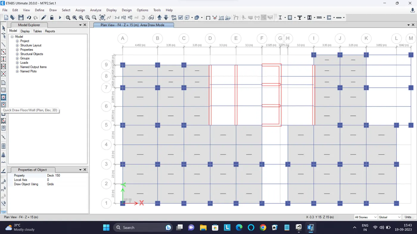
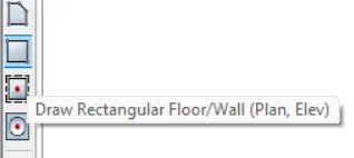
And we use the option of Draw Rectangular Floor/Wall to place the deck slab in the remaining places.
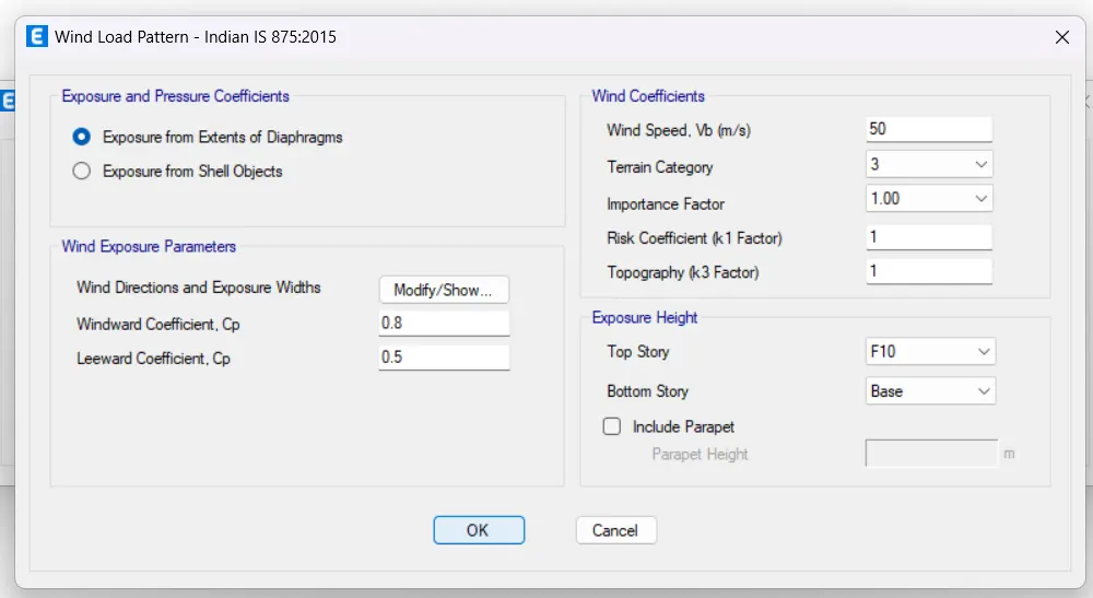
Now,we continue with assigning the load patterns.
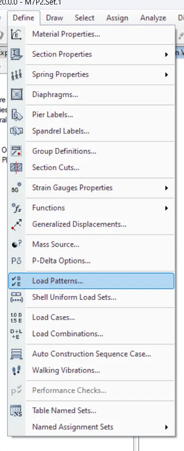
So,we go to Define Tab>Load Patterns...>Add New Load.
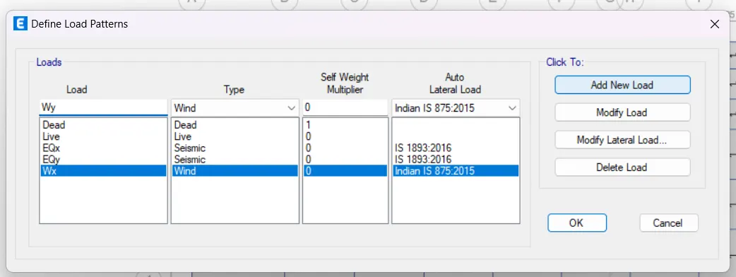
Where we add all the required load patterns but we have to modify the load patterns to suit the required consditions,so,we use the option of Modify Lateral Load... to do this.
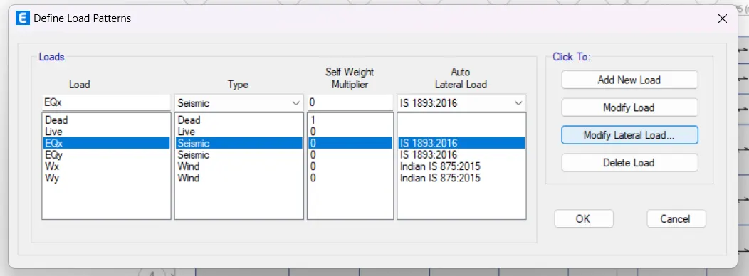
We give the relevant details for each load pattern.
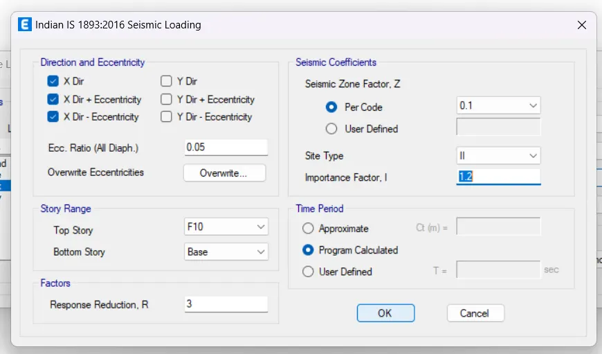
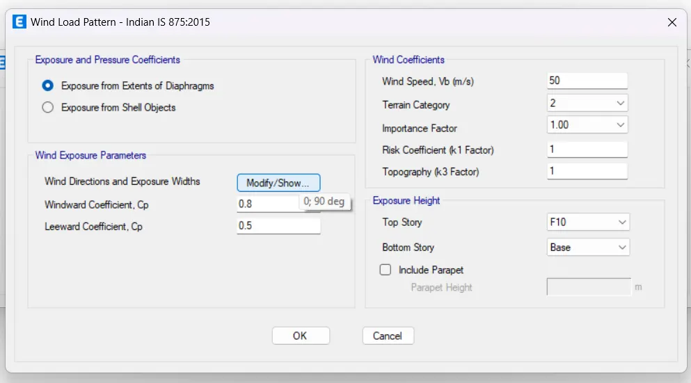
Generally,we create 2 cases for earthquake loads for the 2 directions but for wind load,we just create onle single load pattern as in this case we give the 2 directions of the wind load acting.
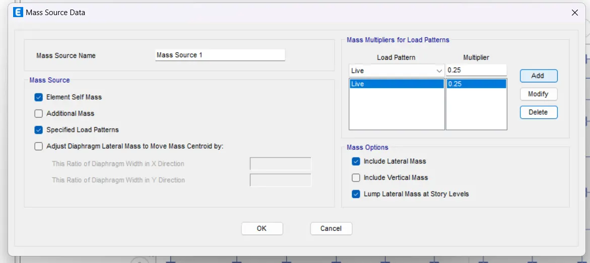
Then we add the mass source for the model.
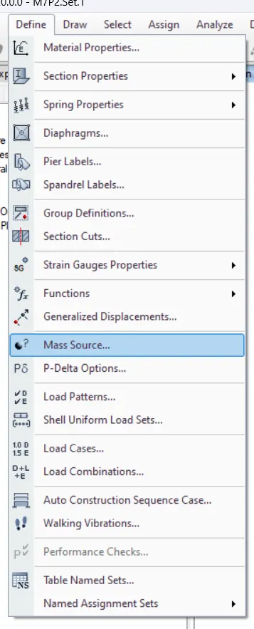
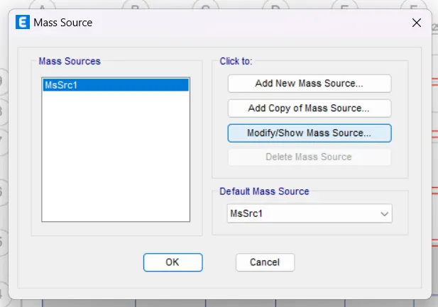
Here,we just add the live load by including the Element Self Mass.
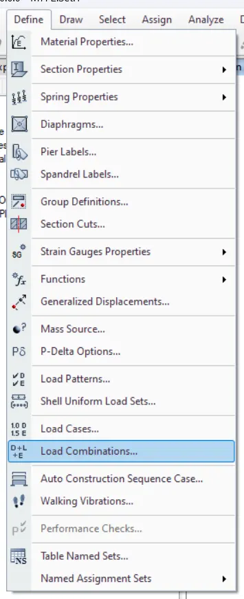
Then,we go to Define Tab>Load Combinations...
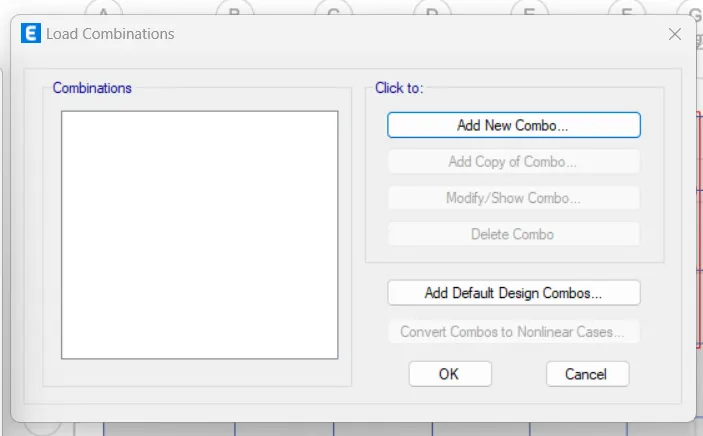
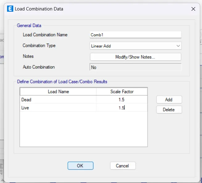
And we add the require load combinatons using the option of Add New Combo...
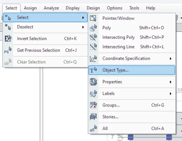
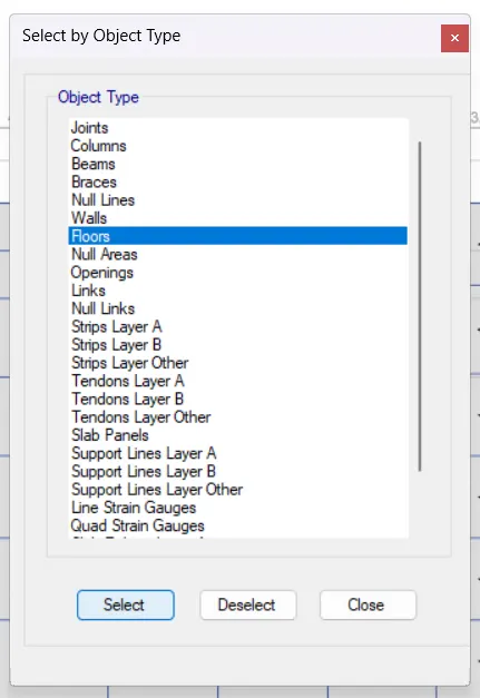
No,we assign the diaphragm by going to Select Tab>Object Type...>Floors>Select.
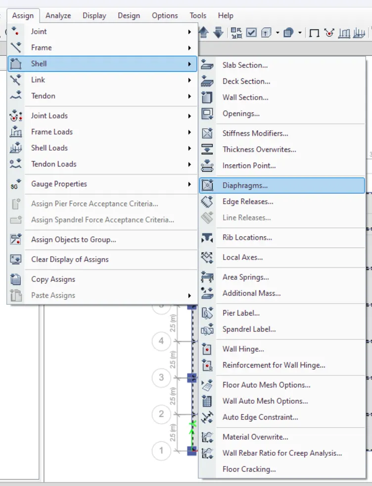
Then,we go to Assign Tab>Shell>Diaphragms...
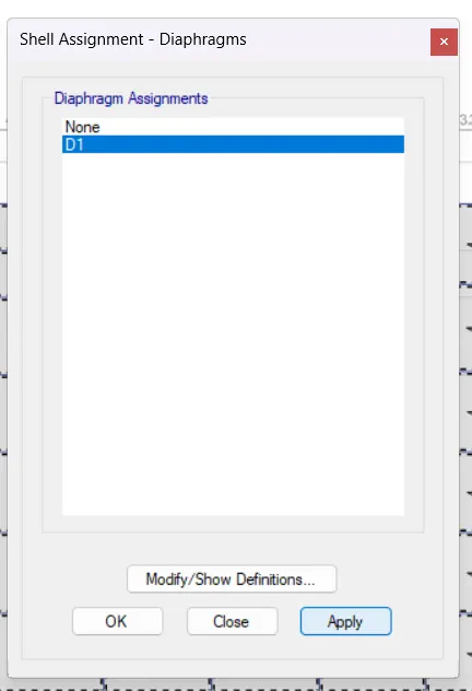
And we assign the required.
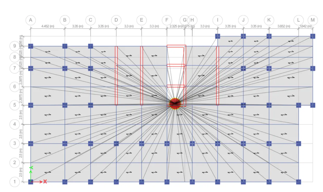
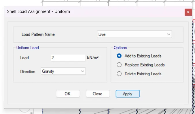
In the similar manner,we apply the live load over the floors.
Then,we run the analysis for the model.
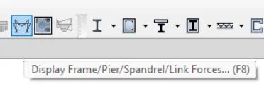
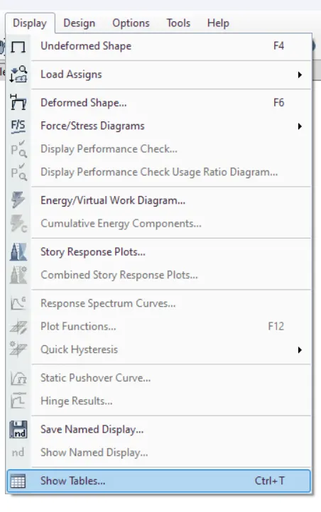
In this similar manner,we even create the other model with the same plan but the secondary beams in this new model will be other direction.We then can find the all the forces to which the members are subjected using the option of Display Frame/Pier/Spandrels/Links...
And we then select the required in the resultant tab.
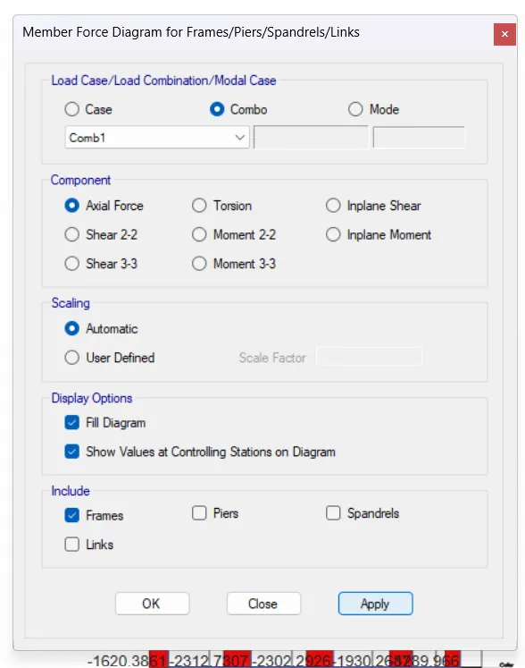
So,in this way,we can get the results and we can evaluate the models created.
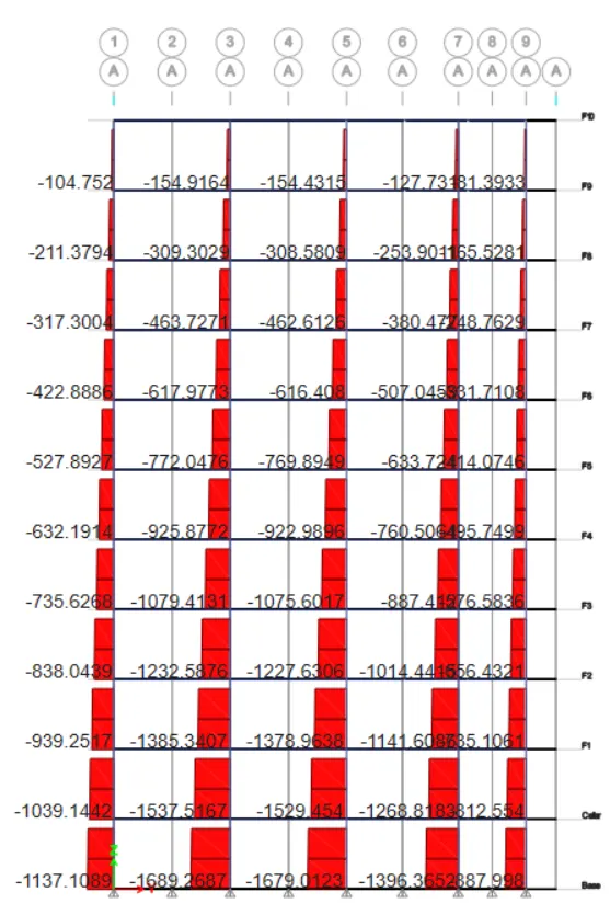
The below be the axial force acting on one set of the columns in one model.
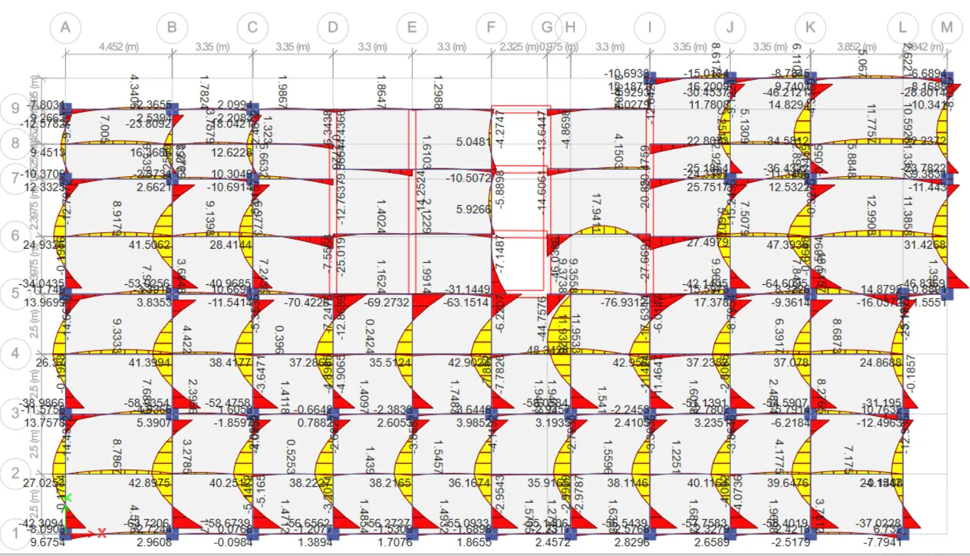
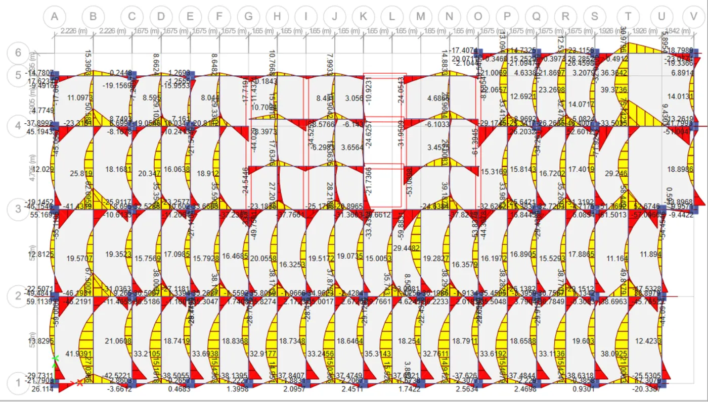
The below be the bending moment acting on the beams of the top floor.
The below be the shear force acting on the same set of beams.
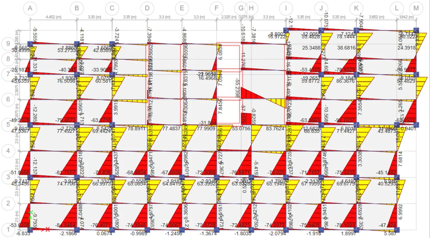
The above all the results obtained when the secondary beams are placed along the longer side of the the building,so,here the no. of secondary beams available are less but they are of more length.
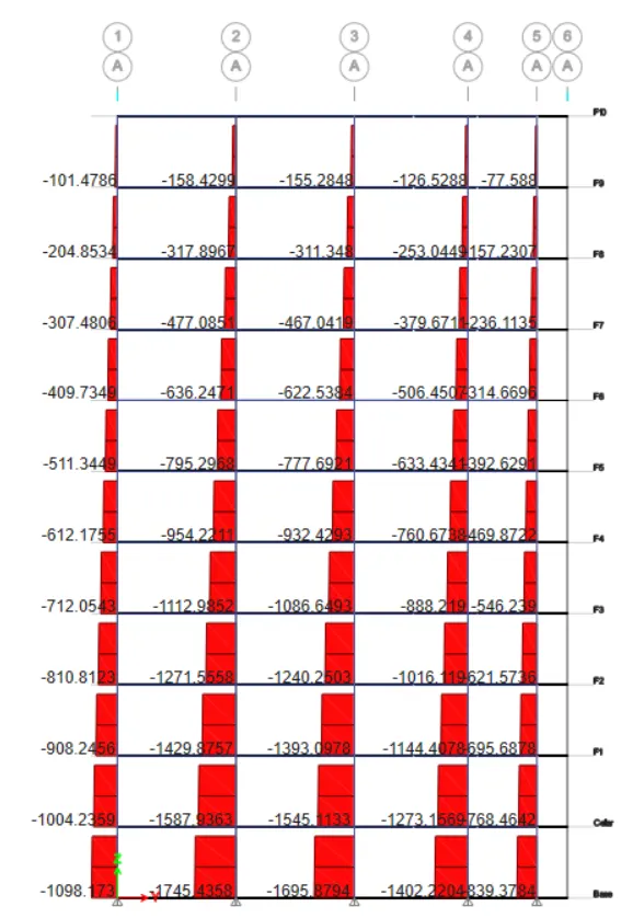
Now,the below be the axial force acting on the same set of columns in a new model.
The below be the bending moment acting on the beams on the same set of the beams in new model.
The below be the shear force acting on the beams on the same set of beams in a new model.
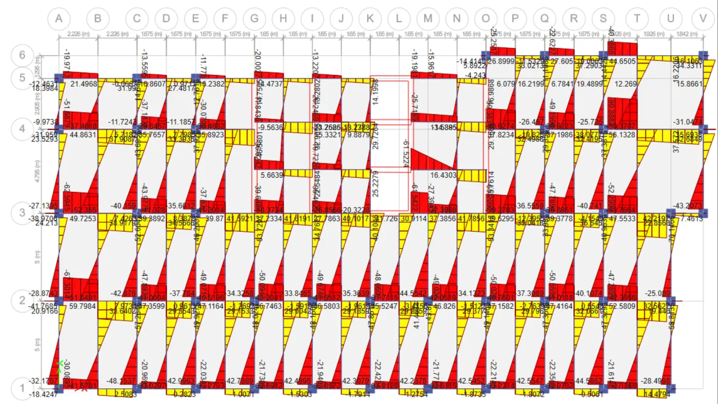
So,the new model above mentioned be the model where the secondary beams are placed along the shorter side of the building,so here more no.of secondary beams are available but these are of shorter length.
By seeing the axial load acting on the columns,both the models are good where the gravity load path is good in both the models.
But while checking the bending moment and shear force acting on the beams,we can find that the model with more no. of secondary beams is good as all the members are subjected to forces and even the forces acting on the beams are mostly uniform and the shape obtained for the both looks good.
But with the first model,we can find that the secondary beams are subjected to very less loads but the primary beams are subject to very high loads,so thus resulting in the unequal carrying of loads thus making the structure uneconomical as it's vain of the provision of the secondary beams in this type.
So,the second model as created above will be the best in load carrying.
Now,we check the base shear for the models.
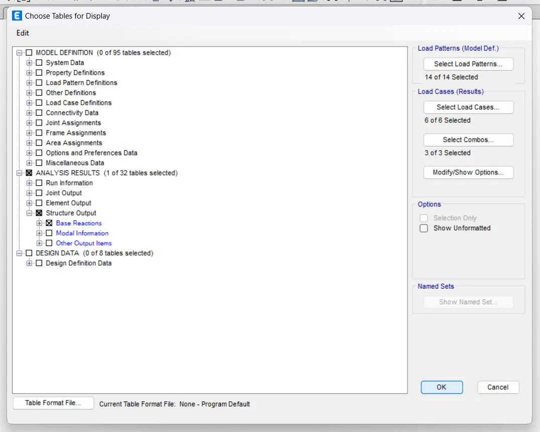
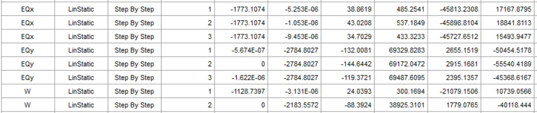
The above is the resultant base shear for the model with less no. of the secondary beams.
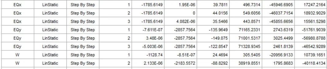
The above be the resultant base shear for the model with more no. of secondary beams.
Here the base shear obtained for the models is almost equal with very less difference.
As we can't design a deck slab using ETABS,we use COMFLOR for designing the deck slab.
COMFLOR
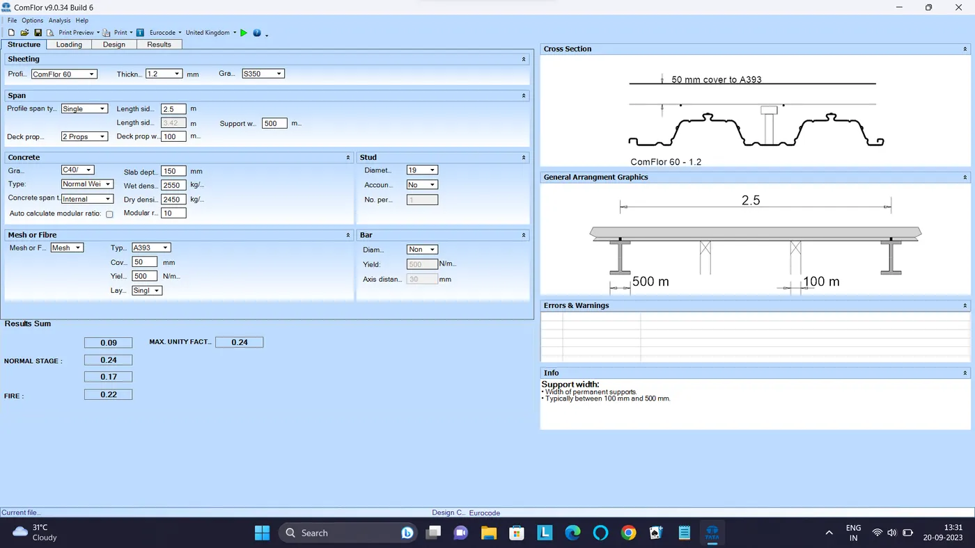
Initially,we open the software,where in the Structure Tab,we select ComFlor 60 type with a thickness of 1.2 mm while the grase of the steel be S350.Where the profile span will be Single as we design a only a bit of the actual slab supported with 2 props where the support width be 500 mm and the prop width be 100 mm and of Internal type.We use studs of diameter of 19 mm along with a mesh of A393 type with a yield strength of 500N/sq.mm with a cover of 50 mm.We then analyze the model.
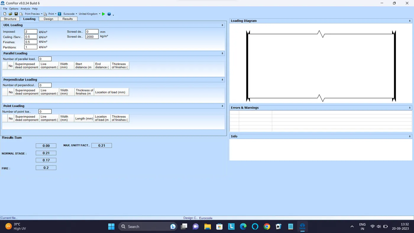
Then,in the Loading Tab,we provide the required loads and then we analyze it again.
In the Design Tab,we provide the other relevant details.We set the Natural Frequency of the deck to 5Hz as given.
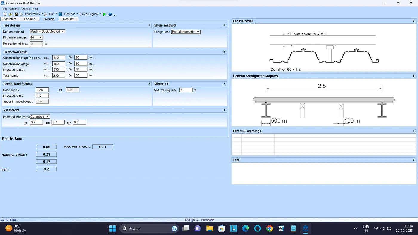
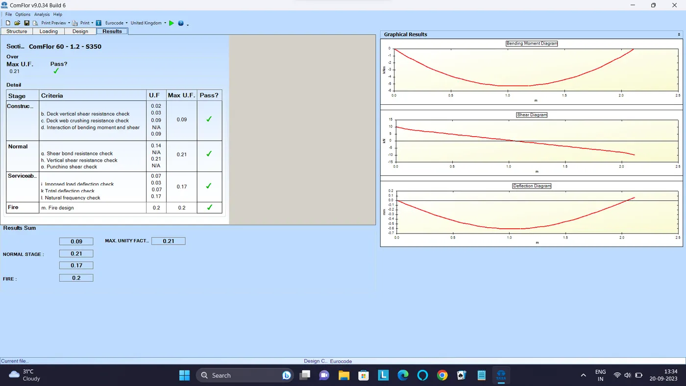
Ultimately in the Results Tab,we could find the overall results in different categories.
To calculate the base shear,we do require the dead load and the live load of the models.Which we drop it from the ETABS.
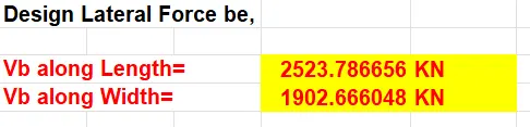
The above be the base shear calculated for the model with less no. of secondary beams.So,though it has some variation but the value is near.
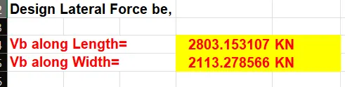
The above be the base shear calculated for the model with more no. of secondary beams.So,though it has some variations but the value is near.