Project 2 - Modeling of 3 phase Induction Motor Drive
Project 2 - Modeling of 3 phase Induction Motor Drive
Part I : Speed Control of Three Phase Induction Motor using V/F Control Method
Question:
This project is focused towards electric vehicle application using an Induction Motor. Student will have to take following steps for a successful model:
- Model 3 Phase Inverter using Simulink (model the parasitic as well) with a switching frequency of 10Khz using 3 phase Squirrel Cage Induction motor, using V/F method, open loop
Design Parameters:
- Power = 100 HP
- DC Voltage = 800 V
- Output Voltage = 460 VRMS – line to line
- Initial Speed = 1500 RPM
- Final Speed = 1000 RPM
- Initial Load Torque = 10 Nm
- Final Torque=20 Nm
- Torque Step Time = 0.1 secs
For Induction Motor model – use Asynchronous Machine from Simulink with Squirrel Cage Preset Model – 05 , for 100HP Motor
For back emf to speed relation, assume a linear rate from 0.25 to 1, with speed changing from 500 RPM to 2000 RPM
Plot speed, stator voltage (line to line) and frequency.
Plot stator line voltage, phase current.
>>> Report:
Abstract:
Three Phase Induction motor was first introduced by Tesla in 1888. He knew that their invention was more efficient and reliable than DC motor. However, the speed control of AC motor is either varying the magnetic flux or changing the number of poles on the motor.Even decades the induction motor gained widespread use, changing the frequency for speed control was remained an extremely difficult task. By 1980s, AC motor drive technology become reliable and inexpensive enough to complete with traditional DC motor control. There are different types of large electric motors used in industries that have very high power consumption. To increase the efficiency of AC electric motor and also provide speed control, these motors are equiped with VFD (Variable Frequency Drive). In addition to speed control, they also provide phase protection, Over-voltage protection and Over-current protection. These VFD's accurately control the speed of standard AC induction or synchronous motors. With VFD's,speed control with full torque is achieved from 0 RPM through maximum rated speed and if required above rated rated speed at reduced torque.
Keywords: Three Phase Pulse Generator, Three phase Inverter, Three Phase Induction motor (Squirrel Cage type) and Matlab/Simulink Software.
Introduction:
Induction motors have been used in the past mainly in applications requiring a constant speed because conventional methods of their speed control have either been expensive or highly inefficient. Variable speed applications have been dominated by dc drives. Availability of thyristors, power transistors, IGBT and GTO have allowed the developement of variable speed induction motor drives. The main drawback of dc motor is the presence of commutator and brushes which require frequenct maintenance & make them unsuitable for explosive and dirty environment. On the other hand, Induction motors particularly Squirrel Cage are rugged, cheaper, lighter, smaller, more efficient, require less maintenance and can operate in dirty and explosive environments.Although the variable speed Induction motor drives are generally expensive than dc motor drives, they are used in number of applications such as fans, blowers, mill run out tables, cranes, conveyers, traction, etc. because of the advantage of Induction Motor. Other dominant applications are underground and underwater installations, explosive and dirty environments.The three phase induction motors are of two types: Squirrel cage and Wound rotor. In squirrel cage, the rotor consists of lomgitudinal conductor bars shorted by circular connectors at the two ends while in wound rotor motor, the rotor also has a balanced three phase distributed windings having same poles as a stator winding. However, in both, stator carries a three phase balanced distributed winding.
The system employed for the control of motion is called as Drives. The drives employing electric motors are called as electric drives. Motion control is required in large number of industrial and domestic applications like transportation systems, rolling mills, paper machines, textile mills, machine tools, fans, pumps, washing machines, etc. Usually, the load requirements can be specified in terms of Speed and Torque demand. Electrical drives are available in wide range becuase of following advantages:
> They are available in wide range of the torque, speed and power.
> They provide higher efficiency.
> They can adaptable to almost any operating conditions such as explosive and radioactive environment, submerged the liquids, vertical mounting and so on.
> Do not pollute the environment.
> They can operate in all four quadrants of speed torque plane.
> Unlike other prime movers, there is no need to refuel or warm-up the motor. They can be started instantly and can be immediately be fully loaded.
Speed Control Method of Induction Motors:
Following methods are employed for the speed control of induction motors:
1) Pole Changing -----------------------------Applicable to Squirrel Cage motor Only.
2) Stator Voltage Control ------------------------- Applicable to both Squirrel Cage And Wound rotor motors.
3) Supply Frequency Control ----------------------------------- ||-------------------------------------------------------
4) Eddy Current Coupling ----------------------------------------|| ------------------------------------------------------
5) Rotor Resistance Control ----------------------------Applicable to Wound Rotor motors only.
6) Slip Power Recovery. ---------------------------- || ------------------------------------------------------.
.Out of above methods, we want to prefere Supply Frequency Control method for speed control of Three Phase Induction Motor.
What is Variable Frequency Drive (VFD) ?
VFD Stands for Variable Frequency Drive. It is a type of controller that drives an electric motor by varying the frequency and voltage supplied to the electric motor. If we does not require the electric motor to run at full speed, the Variable Frequency Drive can be used to come down the frequency and voltage to meet the requirements of electric motor load. It also enables a motor to run above its rated speed by increasing the frequency.
Variable frequency drive is also called as:-
> Variable Speed Drive
> Adjustable Speed Drive
> Adjustable Frequency Drive
> AC Drive
> Microdrive
> Inverter
The Frequency is directly related to the motor speed and it is expressed from the below equation. The Synchronous speed of induction motor can be controlled by varying supply frequency. The formula for synchronous speed of induction motor is given by:
Ns = (120*F) / P -------------------------------------Synchronous Speed Formula--------------Eq. I
where, Ns :- Synchronous speed of motor in RPM;
F :- Supply Frequency in Hz;;
P :- Number of Poles.
Here, F = 60 Hz ; P= 4: then Ns = (120* 60)/4 = 1800 RPM.
Synchronous Speed (Ns) = 1800 RPM
For Induction motor, the rotor speed is always less than synchronous speed of the motor because rotor speed follows stator speed . The actual speed of motor is calculated by
Rotor Speed = (1 - Slip) * Synchronus Speed
Nr = (1-S) * Ns ----------------------------------Rotor Speed Formula -------------------------Eq.II
Where, Slip is nothing but the difference in the speed between stator magnetic field and rotor magnetic field.
The working of three phase induction motor is similar to transformer but the main difference is that the secondary is not a stationary in motor. It is basically works on the principle of Mutual Inductance Phenomenon. The EMF induced in stator winding is given by the formula :
Vs = 4.44 *f * K * T * Φ -----------------------Stator Voltage Formula --------------------------Eq. III
where,
Vs :- Stator Induced Voltage in volt ;
f :- Supply Frequency in Hertz;
K :- Winding Factor;
T :- Number of Stator Windings in Turns:
Φ :- Air Gap Flux in Weber;
Here winding factor K and number of turns T are constant. Therefore, the Voltage Induced in stator is proportional to the product of supply frequency and air-gap flux. If stator drop is neglected, terminal voltage can be considered to the product of frequency and flux.
Stator Voltage = Frequency * Magnetic Flux
V = F * Φ
Φ = V / F ----------------------------------------------Air Gap Flux Formula------------------------------Eq. IV
Any reduction in the supply frequency , without a change in terminal voltage causes an increase in the air-gap flux. Induction motors are designed to operate at the knee point of the magnetization characteristics to make full use of the magnetic material. Therefore, increase in Flux Φ will saturate the motor.
>This will increase the magnetizing current,
>distort the line voltage and current,
>increase the core loss and stator copper loss,
>produce high pitch achostic noise.
While an increase in flux beyond the rated value is undesirable from the consideration of saturation effects.
A decrease in the flux is alos avoided to retain the torque capability of motor. Therefore, the variable frequency control below the rated frequency is generally carried out at rated air gap flux by varying terminal voltage with frequency so as to maintain (V/f) ratio constant at the rated value.
Types of Variable Frequency Drive :
There are three types of variable speed drive and they are as :
1) Voltage Source Inverter Variable Frequency Drive (VSI-VFD) :- This is a simple and cheap drive. It gives a smooth output voltage waveform. But this type of drive has poor power factor, can cause motor cogging below 6 Hz and are non-regenerative.
2) Current Source Inverter Variable Frequency Drive (CSI-VFD) :- CSI has been successfully used in signal processing and industrial power applications. CSI-VFD has only a type that has regerative capability. In other words, they can absorb the power flow back from motor into the power supply. . This type of drive give a very clean current waveform but it requires a large, expensive inductors in their construction and causes Cogging ( Pulsating movement during rotation) below 6 Hz.
3) Pulse Width Modulation Variable Frequency Drive (PWM-VFD) :- Pulse Width Modulation VFD's are most commonly used in industry because of excellent input power factor due to fixed DC bus voltage, no motor cogging, higher efficiencies and lower cost. PWM-VFD uses a series of voltage pulses of different lengths to simulate a sinusoidal wave. Ideally, the pulses are timed so that the time average integral of the drive yields a perfect sinusoidal.
Simulink Model of PWM-VFD induction motor
We want to develope a simulink model of PWM-VFD for three phase Induction Motor with the help of simulink software. The basic design parameter are as follows:
> switching frequency = 10Khz
> Power = 100 HP;
> DC Voltage = 800 V;
> Voltage = 460 VRMS – line to line;
> Initial Speed = 1500 RPM;
> Final Speed = 1000 RPM;
> Initial Load Torque = 10 Nm;
> Final Torque=20 Nm;
> Torque Step Time = 0.1 secs.
The figure 1 shows the main simulink diagram of three phase induction motor drive as follows:
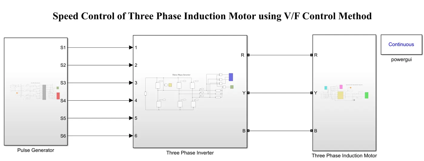
Figure 1. Simulink model of three phase induction motor using V/F method
The main simulink model is divided into three subsystem and they are :
- Subsystem for Three Phase Pulse Generator.
- Subsystem for Three Phase Inverter.
- Subsystem for Three Phase Induction Motor.
>>>Subsystem for Three Phase Pulse Generator :-
In this subsystem we want to generate a three phase sinusoidal voltage waveform and from that we want to generate a three phase gate pulse for six swithces of three phase inverter, as intervetr consists of power electronic switches and it requires a switching pulse for its operation. The following figure 2 shows the subsystem of simulink model of three phase pulse generator.
Simulink model of Three Phase Pulse Generator Subsystem
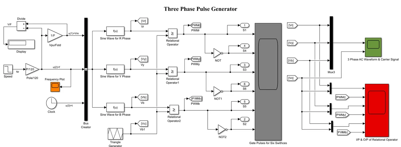
Figure 2. Simulink model of three phase pulse generator subsystem
Before generating a three phase pulse waveform, it is necessary to create a three phase sinusoidal waveform and it is obtained by the simulink function block. This simulink function (fcn) block produces a three phase sinusoidal voltage waveform from three phase voltage equation. The three phase voltage equation are as follows:
Vr = Vm * Sin(2*pi*f *t) -------------------------------------------------For R Phase
Vy = Vm * Sin((2*pi*f*t) - (2*pi/3)) ----------------------------------For Y Phase
Vb = Vm * Sin((2*pi*f*t) + (2*pi/3)) ----------------------------------For B Phase
In the above voltage equation, there are three input function and they are :
> Input function 1 u(1) = Peak voltage (Vm) :
Now we want to maintain the air gap flux (Φ ) remains constant. Therefore,
Air Gap Flux = Peak voltage / Frequency = Per Unit Voltage / Supply Frequency
Φ = Vm / f = 1 / F ----------------------------------From Eq. IV
Therefore, Peak Voltage Vm is given by,
Peak voltage = frequency * Per Unit Voltage / Supply Frequency.
Here, Per Unit Voltage = 1 pu; & Supply Frequency = 60 Hz.
u(1)= Vm = f * 1/ F
This input function u(1) is obtained by multiplying the gain block of 1/ F to the frequency.
> Input function u(2) = Frequency (f) :
Here, we want to change the speed of three phase induction motor in two steps.
The Initial speed N(initial) = 1500 RPM & Final Speed N(final) = 1000 RPM.
Therefore, the frequency can be calculated from the equation I.
Frequency (f) = Ns * ( P/120)
The speed level can be shown by unit step block and it is multiplied with gain block of ( P/120) to obtain the input function u(2).
u(2) = f = Ns * ( P/120)
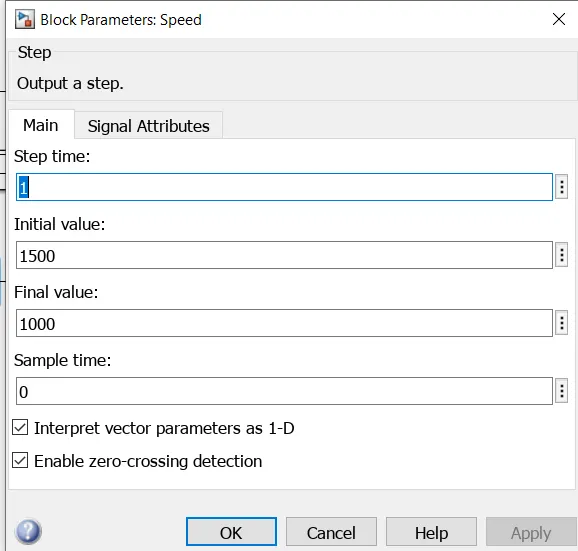
Figure 2. Speed of three Phase Induction Motor set in Unit Step Block
> Input Function u(3) = Instantaneous Time (t):
The magnitude of voltage is changed instantaneously, hence it it is necessary to take the clock signal which acts as a input function u(3).
u(3) = t
This three input functions are given to the three simulink function blocks through a bus creater and produces a three phase pure sinusoidal voltage waveform with per unit voltage. Here we want to generate a three phase pulse waveforms and it is produced from three phase sinusoidal voltages and triangular wave. The switching frequency for triangular generator is 10 kHz.
Simulation Results for Three Phase Generator Subsystem
When we run above subsystem we get following simulation results. Figure 3 shows the three phase sinusoidal voltage waveforms and triangular waveform plotted from three phase AC voltage and carrier signal scope.
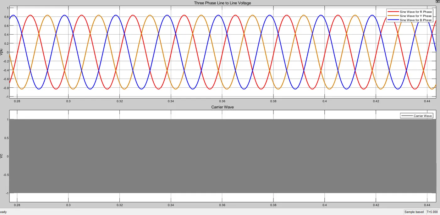
Figure 3. Three Phase Sinusoidal waveform and triangular waveform
How Gate Pulses are formed?
The current method of choice to produce pulse waveform runs a triangular wave and sine wave through a comparator and when a sine wave value is greater than the triangular wave, a voltage output pulse generated. Here, we compare both values of sine wave and triangular wave with the help of relational operator block. If the sine wave value is greater than or equal to carrier wave, the value of pulse is one while if the value is less than carrier wave than the gate pulse value is zero. This is shown in following figure 4. Whether the gate pulses generated by relational operator is right or not which is verified from I/P & O/P relational operator scope.
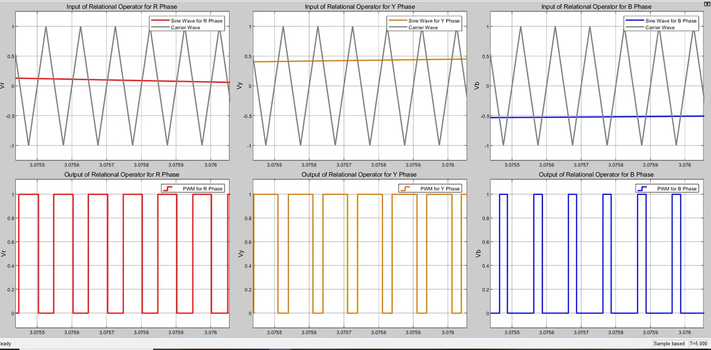
Figure 4. Verification of Gate pulses from Input & Output of relational Operator
These Gate pulses are given to the six switches S1,S2,S3,S4,S5 & S6 of three phase inverter (shown in second subsystem).Out of the six switches, two switches are connected in each phase and both switches are complimentory each other. i.e. if the gate pulse for higher leg swtich is high then at the same time the gate pulse for lower leg switch is low. This is applicable to all phases. Figure 5 shows the generation of gate pulses for the three phase and it is plotted from the scope of generation of gate pulses for six switches.
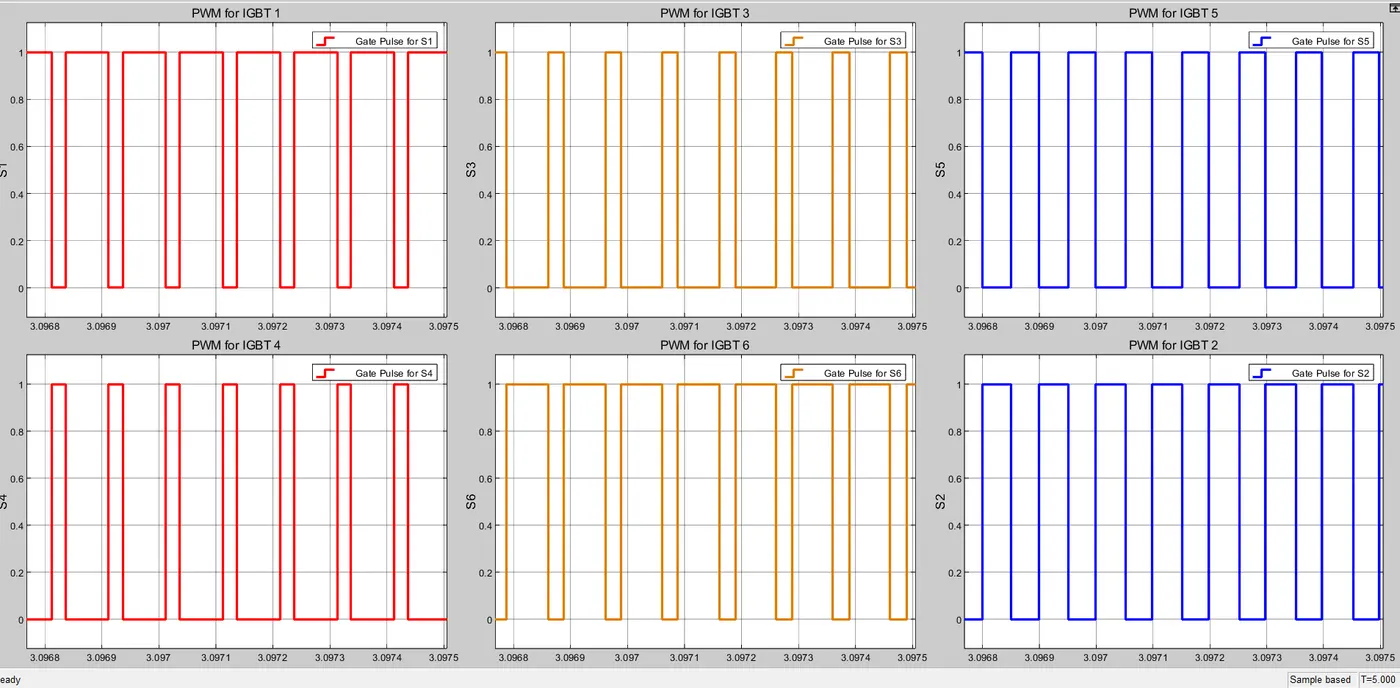
Figure 5. Generation of Gate Pulses for Six Switches
Frequency Plot:
Number of cycles performed in one second is called as frequency. The frequency (Hz) and Speed (RPM) of electric motor is directly proportional to each other and it is expressed from equation I.
Ns = 120 * f /P --------------------------------------------From eq. I
Thus, Frequency (f) = N * P/120
For Speed 1500 RPM, the frequency f1 should be
f1 = 1500 * 4 /120 = 50 Hz.
f1 = 50 Hz.
For Speed 1000 RPM, the frequency f2 should be
f2 =1000 * 4 / 120 = 33.33 Hz.
f2 = 33.33 Hz.
Figure 6 shows the frequency variation of three phase system. This is plotted by the Frequency Plot Scope.
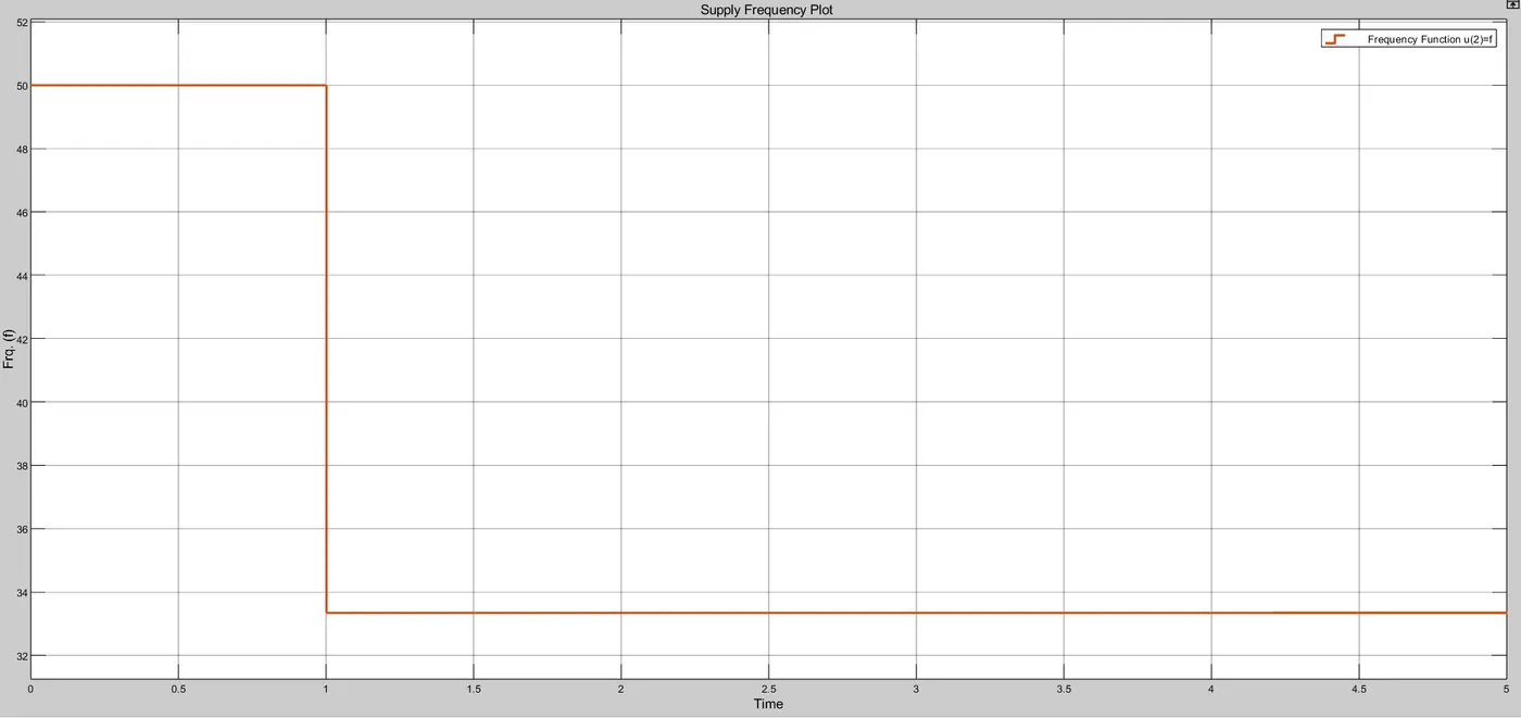
Figure 6. Frequency Plot of three phase System
From the above values of f1 & f2 calculated and in scope are exactly same. Hence, we can say that when we run the three phase induction motor at higher speed , the frequency should be higher and when the speed gets decreases the frequency should be decreases.Means, by changing the frequency value, we can change the speed as well with number of poles kept constant.
>>> Subsystem for Three Phase Inverter :-
We know that inverter is a device which convert the electrical power from direct current to alternating current. Here, we want to control the speed of a three phase induction motor. There are various techniques are available for controlling the speed as mentioned above, but Inverter fed induction motor is a one of the most advantageous method, because
> It is a simple circuit and there is no moving parts in it. hence the friction loss, windage loss and wear and tear are not happened in it.
> By varying the switching states of inverter, we can easily control the speed and torque of electric motor.
> It also improves the power factor.
> It gives higher efficiency.
Figure 7 shows the simulink model of three phase inverter subsystem.
Simulink model of Three Phase Inverter Subsystem
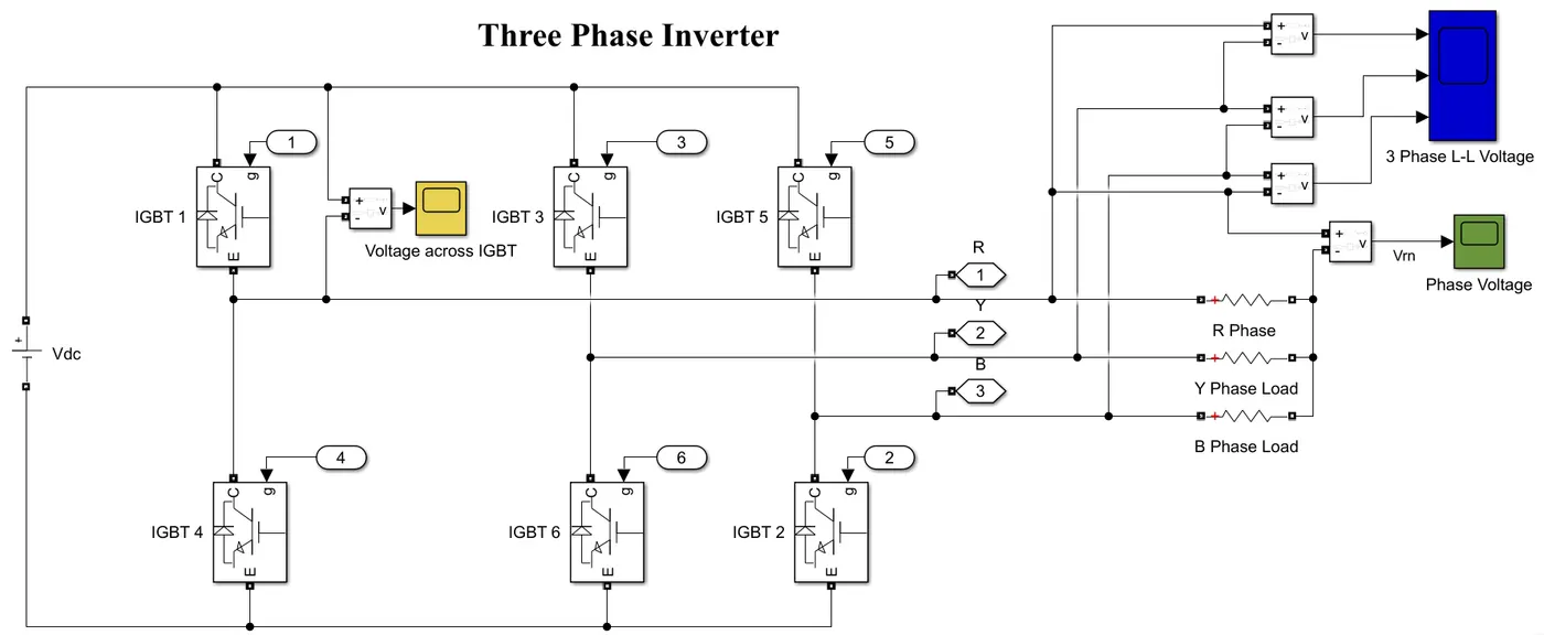
Figuree 7. SImulink model of three phase inverter subsystem
Here, three phase induction motor is fed from three phase inverter and hence this three phase inverter is also called as Variable Frequency Drive. Because we can control the speed of induction motor by changing the frequency and voltage level of this inverter. It consistes of six switches S1,S2,S3,S4,S5 & S6. The current electric component of choice to generate the voltage pulse is either Insulated Gate Bipolar Transistor (IGBT) or Metal Oxide Semiconductor Field Effect Transistor (MOSFET), Silicon Controlled Rectifier (SCR). Depending upon the power demand at load side and switching frequency, it should be selected. If the power demand is high and switching frequency is low, IGBT is preferred for this and when the power demand is low and switching frequency is high, MOSFET is preffered for this application. Here, we want to fed the three phase induction motor from three phase inverter, and the power rating is high i.e. 100 HP.
1 HP = 746 Watt
100 HP = 74600 Watt = 74.6 kW = 75 kilo-Watt
Therefore, the power demand is high and switching frequency is low i.e. 10 kHz. Hence, we preferd the IGBT acts as a switch. There are six IGBT switches are connected. Each phase consists of two switches and they are complimentory to each other. In other words, when the upper switch is turn ON, the lower switch must be turn OFF and vice versa. This takes the precausion for avoiding the short circuit condition across the input supply. Here the input voltage is 800 Volt DC and this value is taken from call back function.
Let us assume that the three output terminals of the inverter is given to three phase resistive load whose load resistance is 1 ohm and they are connected in star. It is only shown in simulink model to fetch the input terminals i.e. connection port for three phase induction motor in subsystem 3. IGBT 1 and IGBT 4 are connected in R-phase, IGBT 3 and IGBT 6 are connected in Y-phase, IGBT 5 and IGBT 2 are connected in B-phase. Both the switches are complimentory to each other. This is shown by gate pulses from figure 5.
When we run above subsystem, we obtained following simulation results like voltage across IGBT switch, line to line voltage and phase voltage of three phase inverter.
Simulation Results for Three Phase Inverter Subsystem
Voltage Across each IGBT Switch :
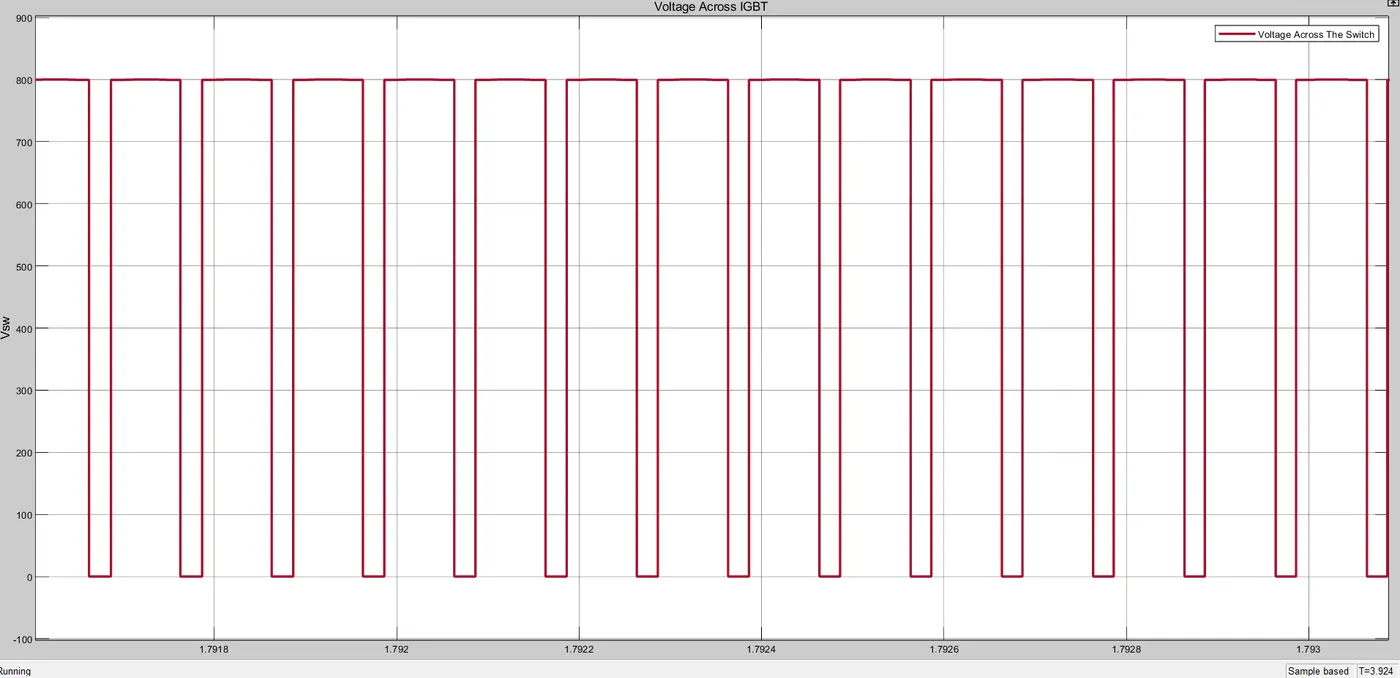
Figure 8. Voltage across each IGBT Switch
From figure 8, we can say that the voltage across each IGBT switch is same as that of inputt dc voltage. we have shown only for first IGBT switch, but voltage remains same across each switch. As the switch is ideal, hence there is no voltage drop across the switch but practically there is some voltage drop across each switch due to conduction and switching losses.
When we run above subsystem of three phase inverter, we obtained three phase line to line voltage in figure 9 and phase voltage in figure 10 shown by 3 phase L-L voltage scope and phase voltage scope respectively.
Three Phase Inverter Output Voltage (Line-LIne) :
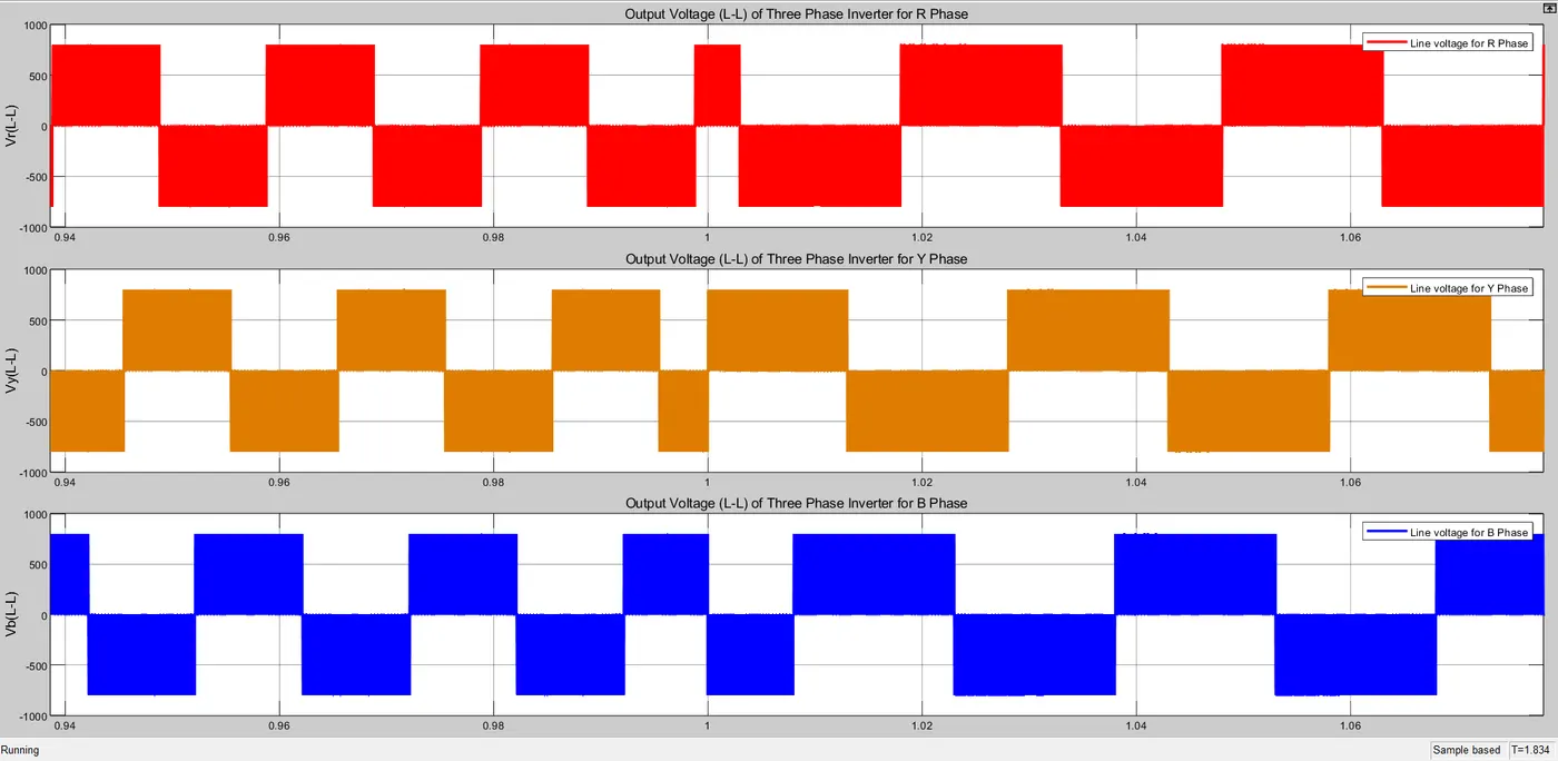
Figure 9. Three Phase (L-L) voltage of three phase inverter
From above graph, we observed that the output voltage (line to line) of three phase inverter is "Rectangular" waveform. Variable Frequency Drive (VFD) does not produce a Sinusoidal Output. The magnitude of output voltage is 800 volt line to line which is fed to stator of induction motor. This rectangular waveform would not be good choice for a general purpose distribution system, but it is perfectly adequate for a motor. We also observed that when the speed of motor is high, the frequency is also high and vice versa.
Three Phase Inverter Output Voltage (Line-neutral) :
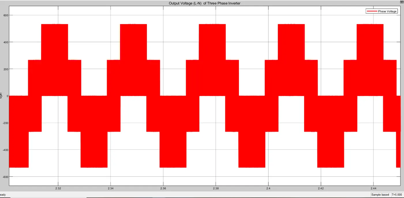
Figure 10. Three Phase (L-N) voltage of three phase inverter
Figure 10 shows the output phase voltage of Variable Frequency Drive in which the magnitude is 530 volt. So the load resistance or three phase stator winding of induction motor is connected in star configuration, hence the phase voltage is equal to
V(phase) = V(line) / sqrt(3) --------------------------------Formula
V(phase) = 800 / sqrt(3) = 461.88 volt. = 462 volt.
Now the three phase inverter is a two level inverter hence we get two steps in voltage waveform. The line current and phase current should be same for star configuration.
>>> Subsystem for Three Phase Induction Motor :
The output of variable frequency drive i.e. three phase induction motor is supplied to the three phase stator winding of induction motor. We know the working principle of three phase induction motor that when a three phase supply is given to three phase stator winding, the emf gets induced in it due to self inductance. This emf drives the stator current through stator winding. This stator current produces a magnetic flux and complete their path through air-gap, rotor core and stator core also. This magnetic flux rotates at synchronous speed in air gap between stator and rotor. As the magnetic flux is rotating and at starting the rotor conductors are stationaory, the rotor conductors cut the magnetic fielf, the emf gets induced in it also. As the rotor conductors are short circuited by end rings, hence the induced emf drives the rotor current and responsible for generating their own magnetic flux. Now this rotor flux obeys the stator flux and rotate in an air gap also. Due to interaction of two fluxes in air gap, the torque is produced on rotor and hence the motor starts rotate. The rootor speed is always less than stator spped. The simulink model of three phase induction motor subsystem is shown in following figure 11.
Simulink model of Three Phase Induction Motor Subsystem
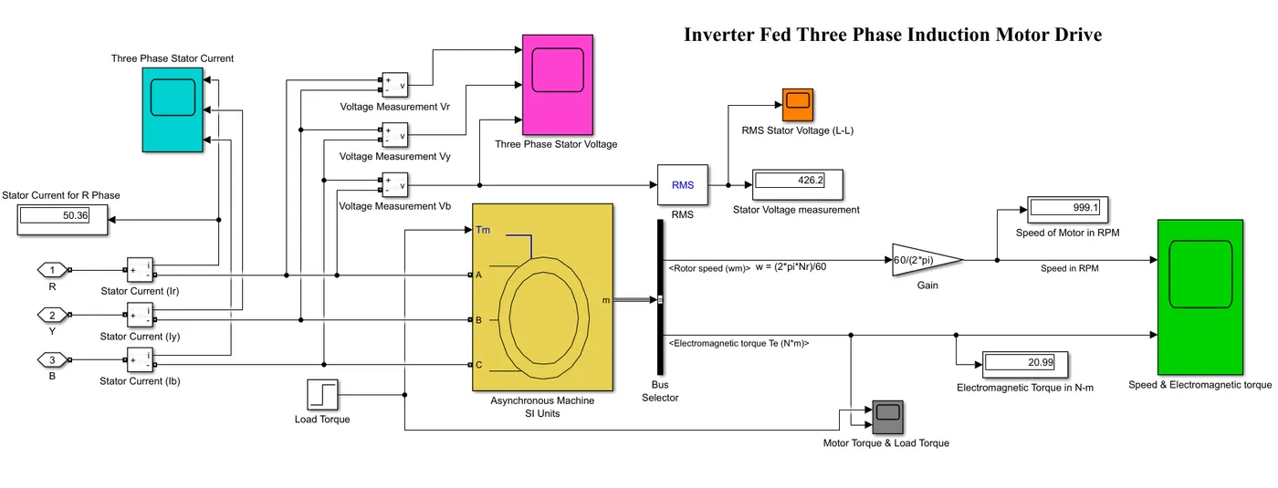
Figure 11. Inverter fed Three Phase Induction Motor Drive Subsystem
We have an 100 HP induction motor, hence we choose a preset model of squirrel cage type in which the motor rating is 100 HP, 460 Volt, 60 Hz, 1780 RPM. This three phase induction motor is also called as asynchronous machine because it always runs below synchronous speed. Here we have provided a load torque in two steps as initial torque is 10 Nm and final torque is 20 Nm. It is given by unit step block and the load torque step time is 0.1 second. Following figure 12 shows the parameter of load torque.
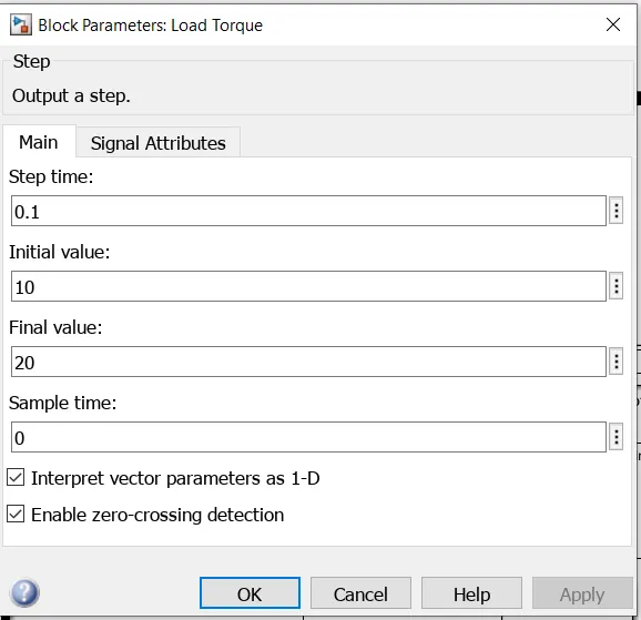
Figure 12. Load Torque Parameter in unit step block
Simulation Results for Three Phase Induction Motor Subsystem
When we run above simulink model substem, we got various waveforms like three phase stator line to line voltage and stator current, electromagnetic torque, speed of motor, stator RMS voltage etc.
Three Phase Stator Voltage (L-L):
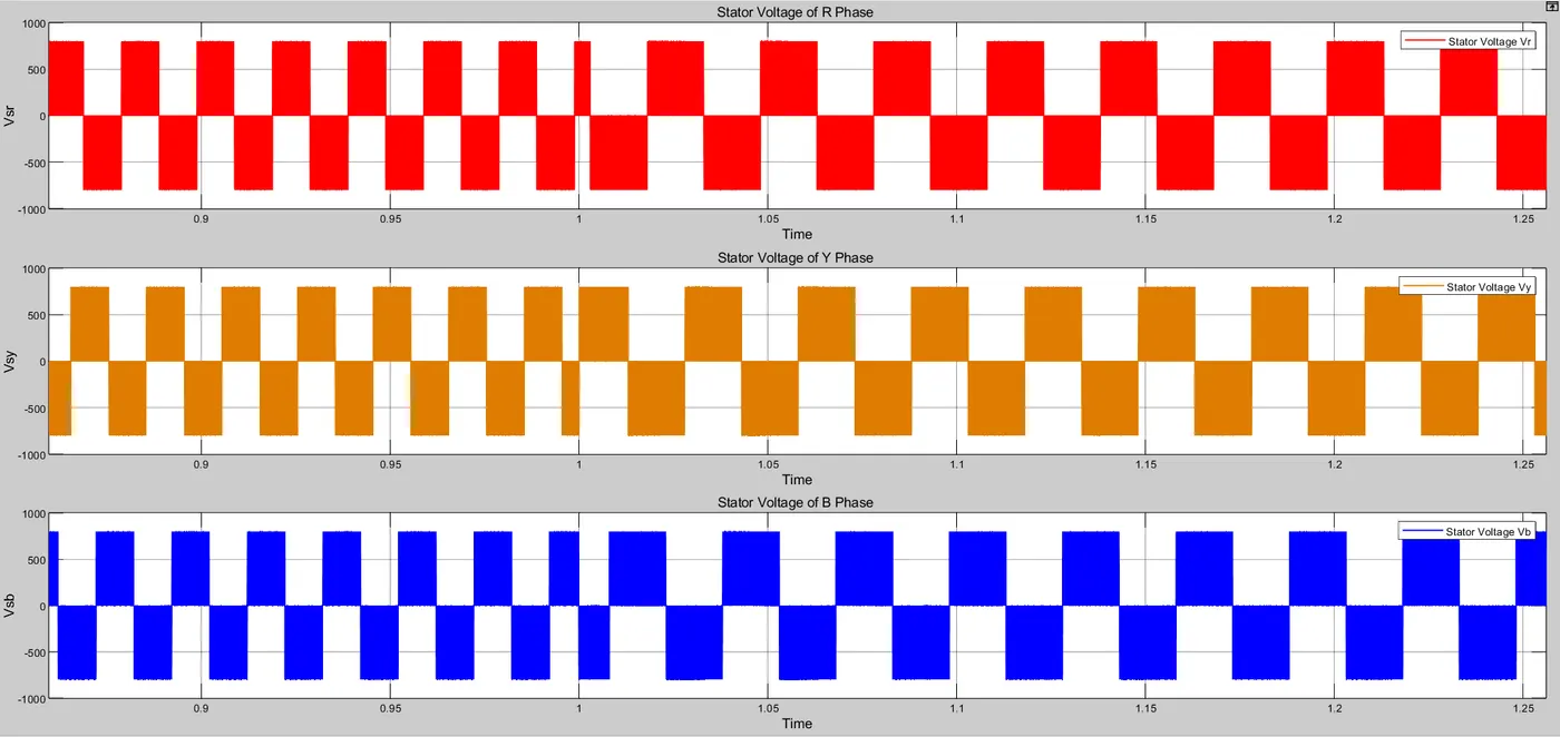
Figure 13. Three Phase (L-L) Stator Voltage of Squirrel Cage Induction Motor
From above graph 13, we can say that when a three phase voltage is supplied by three phase inverter, the voltage waveform must be in a rectangular shape. The stator line voltage is 800 volt. And we also observed that for high speed, the frequency is high and vice versa for low speed.
Three Phase Stator Current:
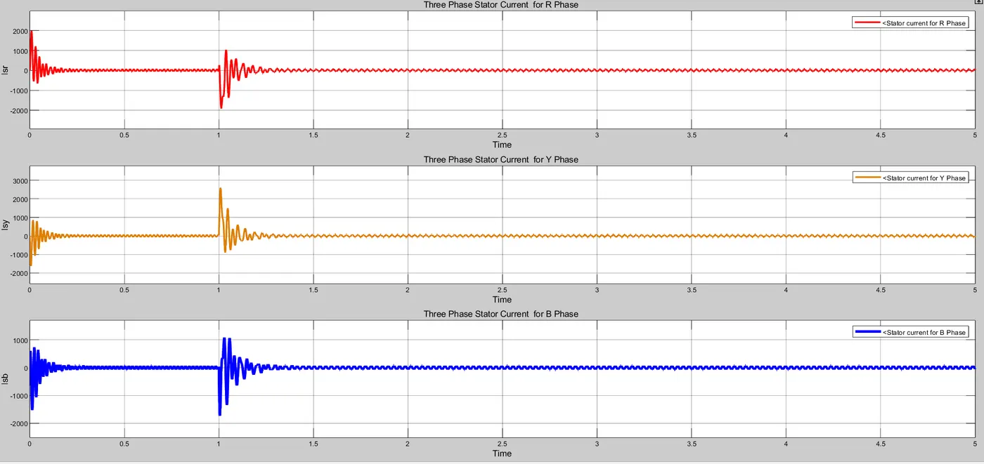
Figure 14. Three Phase Stator Current (Zoom Out) waveform
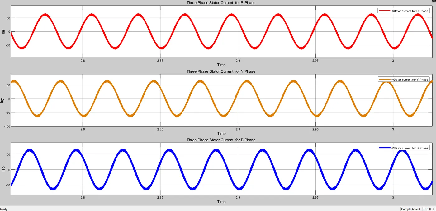
Figure 15. Three Phase Stator Current (Zoom IN) waveform
Figure 14 and 15 shows the three phase stator current in Zoom out & Zoom In version. From above figure 15, we observed that the three phase stator currents are sinusoidal in nature with 120 dagree phase shift.The peak value of stator current is near about 54 ampere.
As the motor power rating is 75 kW and line voltage is 800 volt. Hence, we can calculate the stator current :
Motor input power = Sqrt(3) * Stator Voltage (L) * Stator Current (L or P)
75 *1000 = Sqrt(3) * V(L) * I(L) = Sqrt(3) * 800 * I
Hence, I = 75*1000 / ( Sqrt(3) * 800) = 54.126 Ampere.
Stator Current (I) = 54.126 Ampere.
As the calculated value and plotted value are almost similar. Hence, we can say that the VFD supplies an accurate electric power to the load. i.e. three phase induction motor.
RMS Stator Voltage (L-L) :
We want to obtain the RMS Stator Voltage.So it is obtained by connecting RMS block between any one of the phase voltage terminal and scope. Figure 16 and 17 shows the RMS Stator Voltage shown by RMS Stator Voltage Scope.
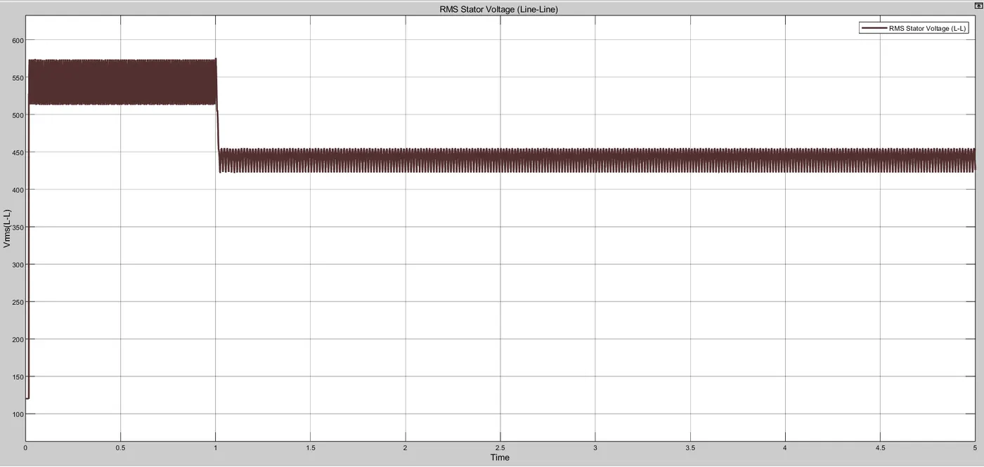
Figure 16. RMS Stator Voltage (Zoom Out)
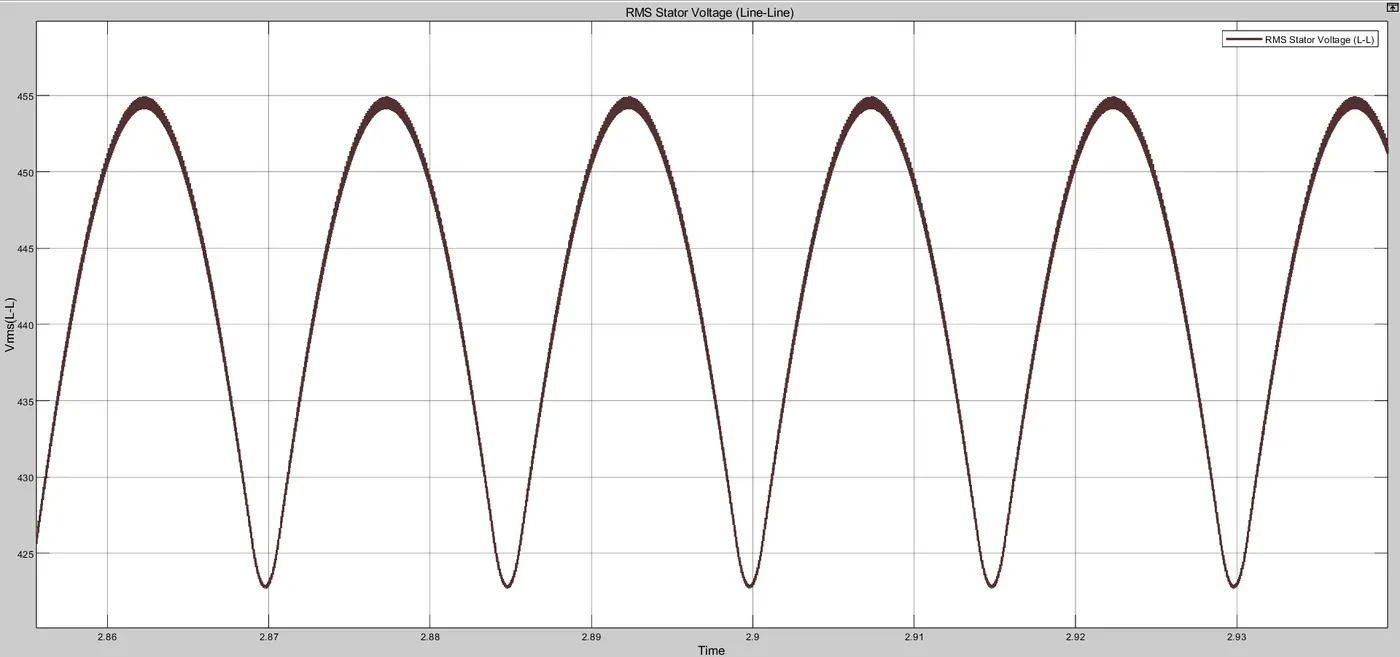
Figure 17. RMS Stator Voltage (Zoom In)
From above figure 17, we observed that the RMS value of Stator Voltage is near about 455 volt for speed 1000 RPM and it is higher i.e. 550 volt for 1500 RPM.
Load Torque & Electromagnetic Torque :
> Torque is defined as a rotational force act on object for a certain distance in circular fashion is called Torque. In short, torque is nothing but the twisting force.
> Electromagnetic torque and load torque are different.
>Electromagnetic torque is the torque that is produced inside the machine which makes the machine rotate while load torque is the torque that is applied externally with brake drum and spring balance.
> Electromagnetic torque can be varied by varying the speed of machine but the load torque is fixed.
> When the electromagnetic torque become higher than load torque, the motor gets accelerate whereas the electromagnetic torque become lower than load torque, the motor gets deaccelerate.
If Te > TL ---------------------------------------------Motor Accelerate
If Te < TL -------------------------------------------- Motor Deaccelerate
There are so many forces act on machine like aerodynamic force, rolling resistance force, gravitational force, etc.Due to this force, the speed of machine get reduces. because these forces opposes the machine to accelerate. Thus, load torque is opposite to electromagnetic torque in direction. We have provided two torque level for this motor by means of step block as shown in figure 2. So we obtained the following torque waveform in figure 18.
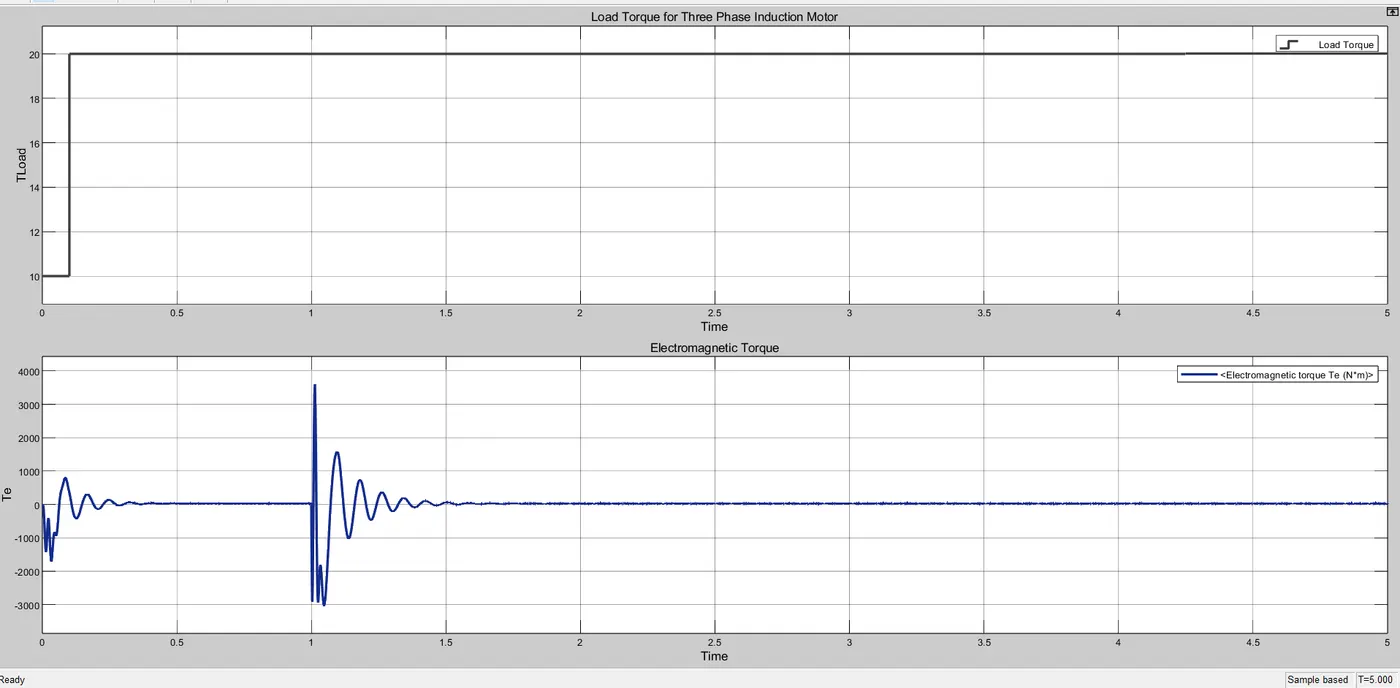
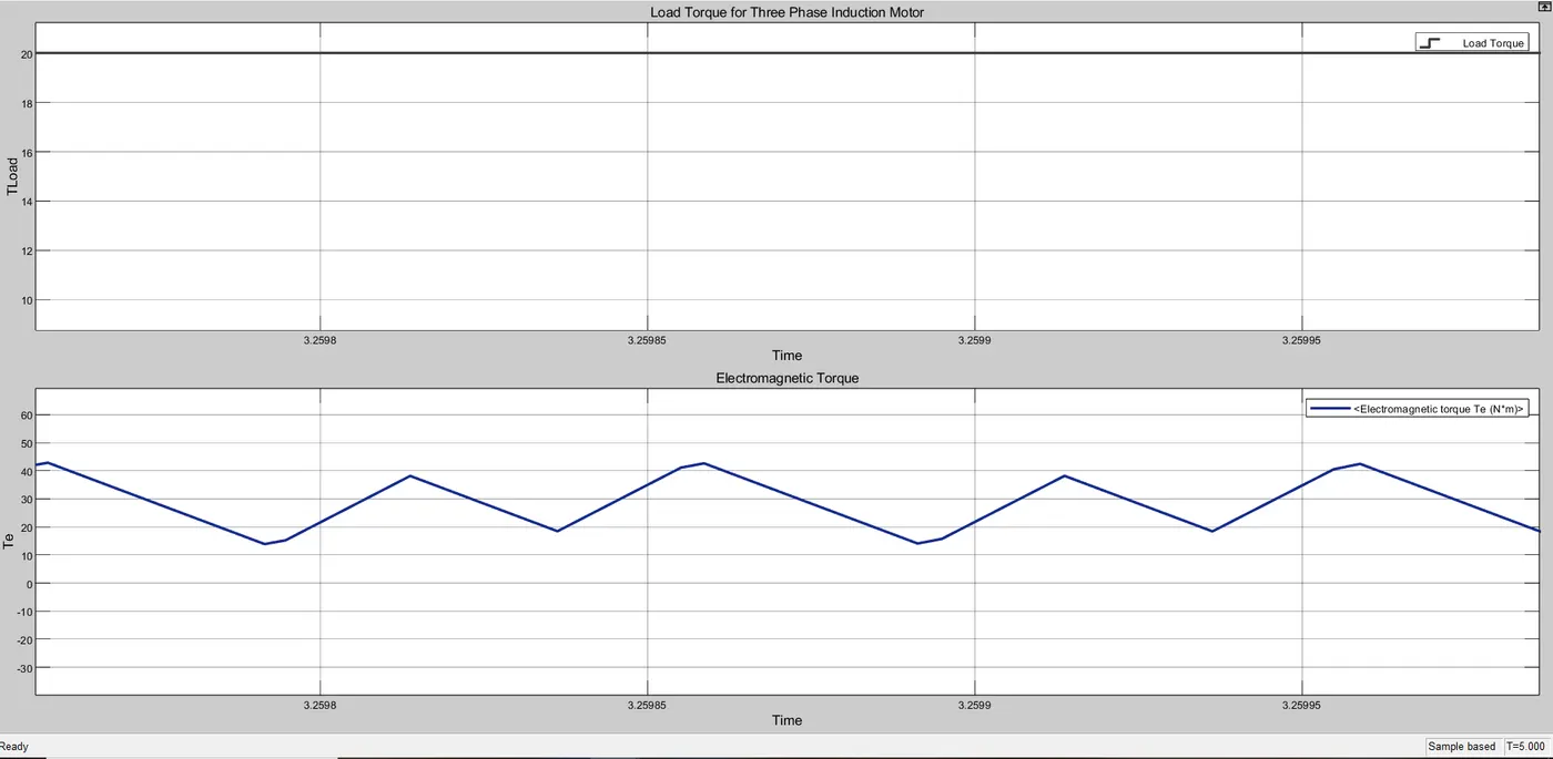
Figure 18. Load Torque and Electromagnetic torque of three phase induction motor
From the above figure, we can say that the load torque is 20 Nm which is almost constant but electromagnetic torque is higher than load torque and is equal to 35 to 40 Nm. Therefore, the motor gets accelerate.
Speed of electric Motor:
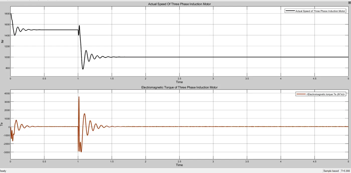
Figure 19. Speed and electromagnetic torque of Induction motor
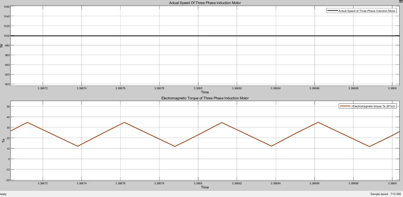
Figure 20. Speed and electromagnetic torque of Induction motor (Zoom In)
From Figure 18, we observed that the initial speed is 1800 RPM, and this speed is synchronous speed.
Here, F = 60 Hz ; P= 4: then Ns = (120* 60)/4 = 1800 RPM.
Synchronous Speed (Ns) = 1800 RPM
We know that the electric motor always run below synchronous speed. Therefore, we have set 1500 RPM and 1000 RPM in unit step block as shown in figure 2. This speed is shown in above graph. When the motor speed changed, there are some transient occure at speed but after few instant, it again back to its normal speed. In figure 20, we also observed that the electromagnetic torque is near by equal to 35 Nm which is higher than load torque. Hence, the motor gets accelerate.
Advantages of V/F Method:
> It is the simplest controller in structure.
> It does not uses any feedback .
> It is also called as scalar control and imposing a constant relation between voltage and frequency.
Disadvantages of V/F Method:
> We cannot change the speed as per the load requirement due to the absense of speed feedback.
> This controller doesn't achieve a good accuracy in both speed and torque responses.
> The stator flux and torque are not controlled directly.
*********************************************************************************************************************************************************************************************************
2. Use the 3 phase inductor motor theory to derive the transfer function of 3 phase Induction Motor.
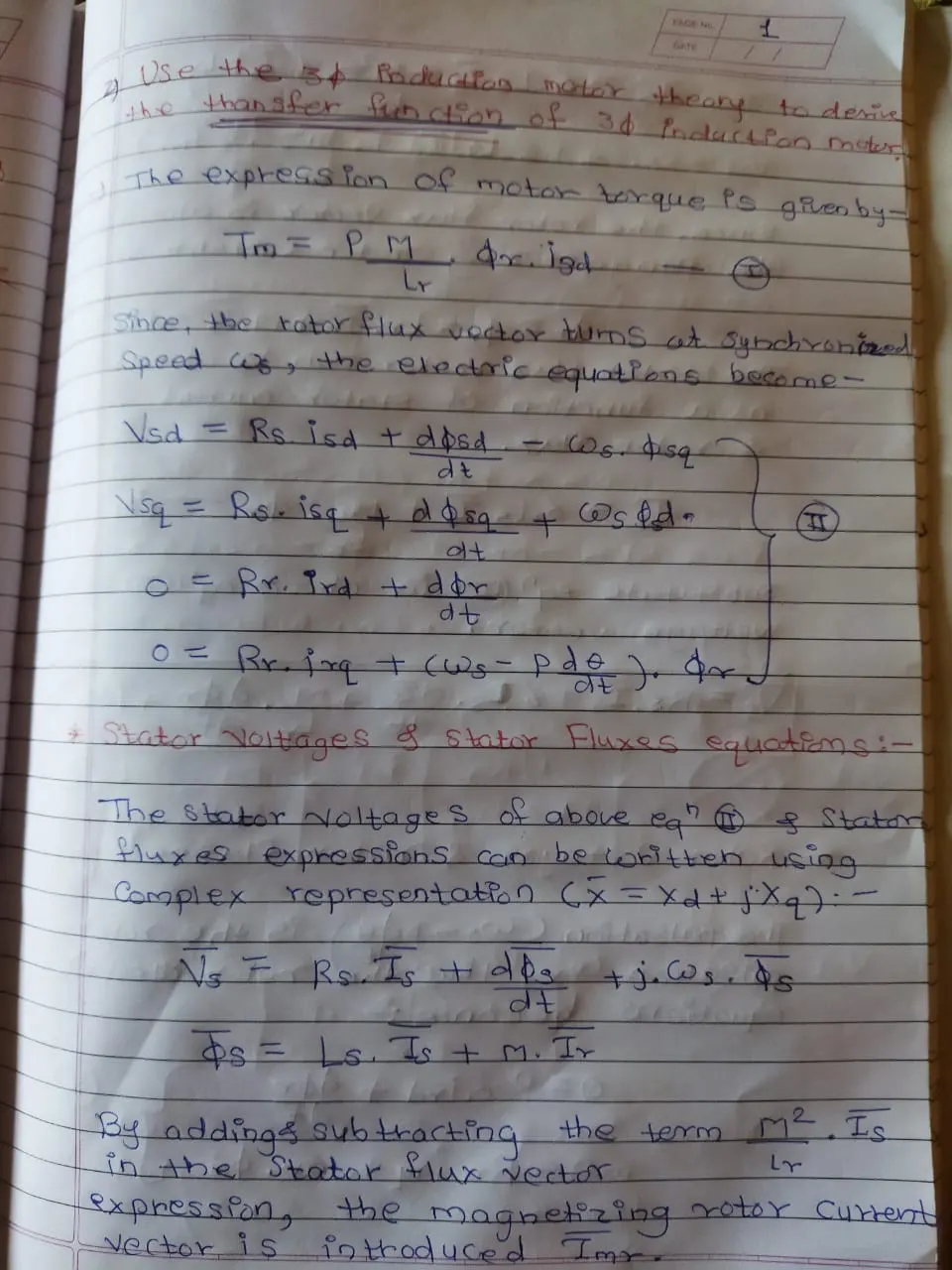
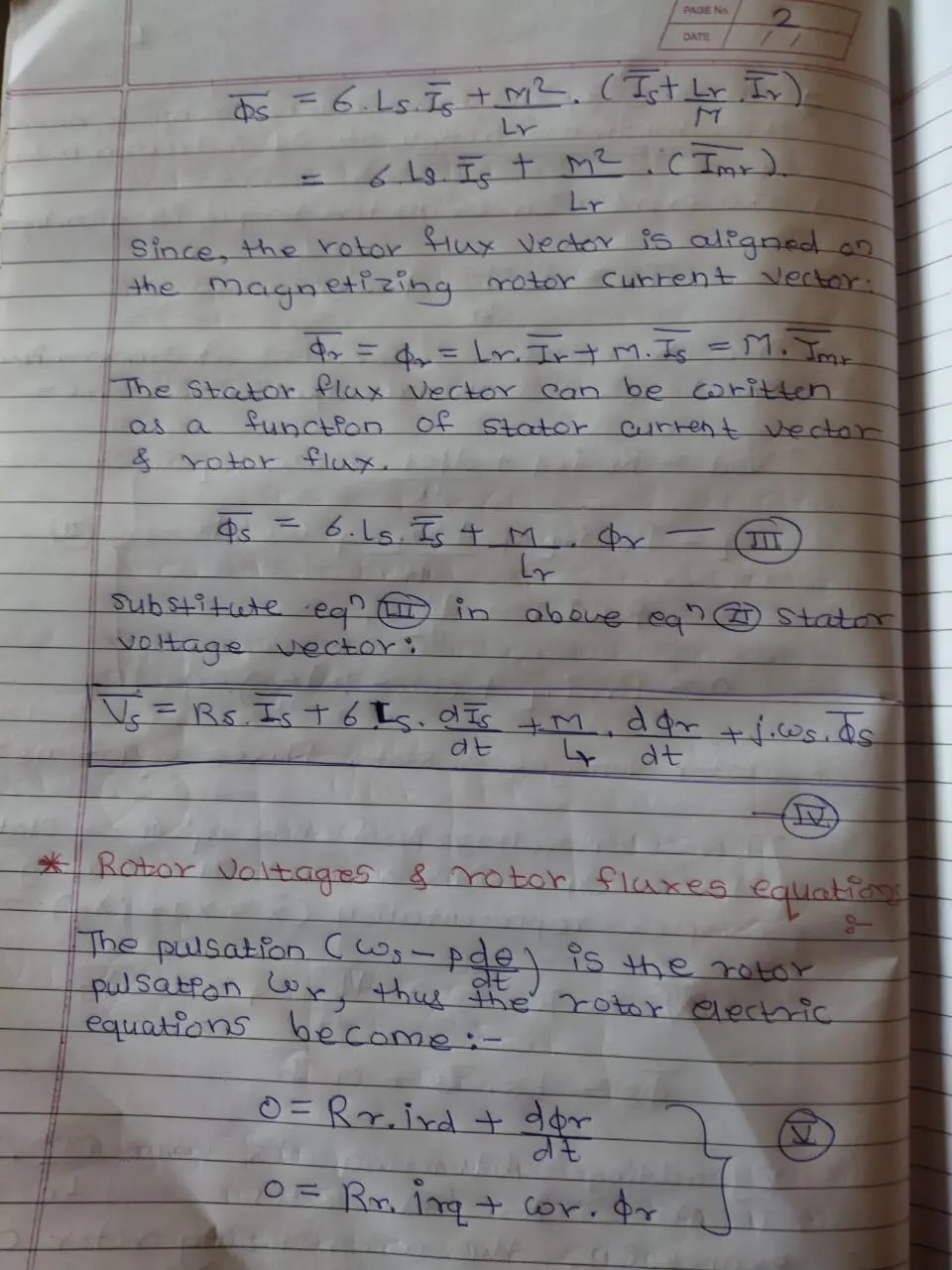
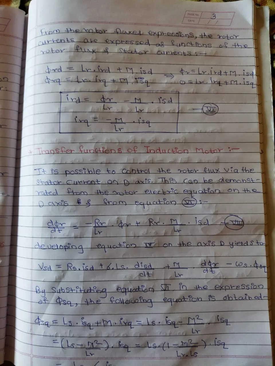
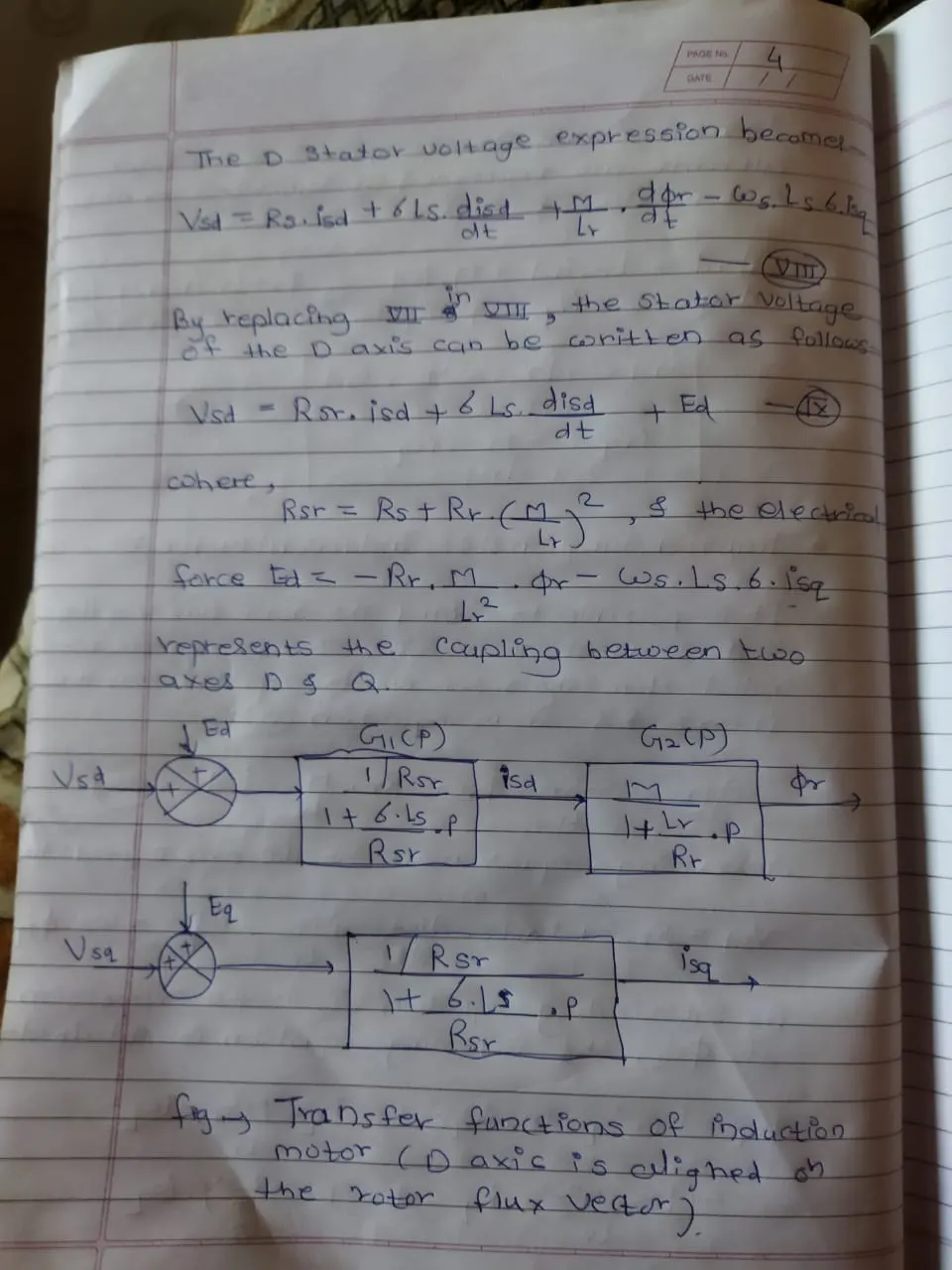
Figure 1. Transfer Function Theory of Three Phase Induction Motor
**************************************************************************************************************
3. Model 3 phase induction motor with a 3 phase inverter using Direct Torque control using an Average Model, Implement both torque and flux control to achieve desired power.
Design Parameters:
- Initial Speed = 0 RPM
- Flux Target = 2.5 webers
- DC Voltage = 500 V;
- Fundamental Frequency = 60 Hz
- Speed Step Time = 0.01 secs
- Determine fundamental speed based upon fundamental frequency
- Determine the switching sequence for direct torque control
- Moment of Inertia = 0.1 Kgm^2
- Load Torque Initial = 0 Nm
- Final Load Torque = 50 Nm
- Torque Step Time = 0.03 secs
Motor Parameters: (Create an Average Model)
- Stator Resistance = 0.5 Ohms
- Rotor Resistance = 0.2 Ohms
- Stator Leakage Inductance = 20 mH
- Rotor Leakage Inductance = 10 mH
- Magnetizing Inductance = 200 mH
- Number of Poles = 4
- Torque to Speed
Introduction:
Induction motor is one of the most important parameter of all industries. It is widely used in various sectors. In Some applications, we want to control the speed of electric motor above its rated speed.Basicaaly there are two types of control mechanism available :
1) Scalar Control 2) Vector Control
1) Scalar Control :
In scalar control mechanism, to maintain the magnetic flux constant, the ratio of Voltage (V) & Frequency (F) is kept constant. In this method, the voltage and frequency of inverter is changed so that the magnetic flux remains constant. This V/F control method is also called as Scalar Control. This V/F control method is open loop control.i.e. there is absence of feedback system in it.
2) Vector Control:
In this type of controller, there are control loops for controlling both torque and flux. There are two types of vector control method:
1) Field Oriented Control
2) Direct Torque Control.
In Direct Torque Control (DTC), it is possible to control directly the stator flux & torque by selecting the appropriate inverter state. Its main features are:
> Direct torque control and direct stator flux control
> Indirect cotrol of stator current and voltage
> Approximately sinusoidal stator fluxes and stator currents.
> High dynamic performance even at locked rotor.
Direct Torque Control :
Direct Torque Control was proposed as an alternative to the field oriented vector control in the middle of 1980s for AC machine control. This strategy based on the direct determination of inverter switching states to control the voltage source inverter (VSI) through a switching look up table. This DTC was proposed by TAKAHASHI and DEPENBROKE in 1980s.
1) Conventional Direct Torque Control (By Using Hysteresis Based)
2) Space Vector Modulation Direct Torque Control (SVM_DTC)
3) Fuzzy-PI Speed Controller Direct Torque Control (Fuzzy-PI DTC).
Here we want to model a three phase induction motor using conventional direct torque control (Hysteresis Based). The simulink model is already inbuild in simulink software but here we want to made some changes in motor parameter and run the simulation.
Simulink Diagram:
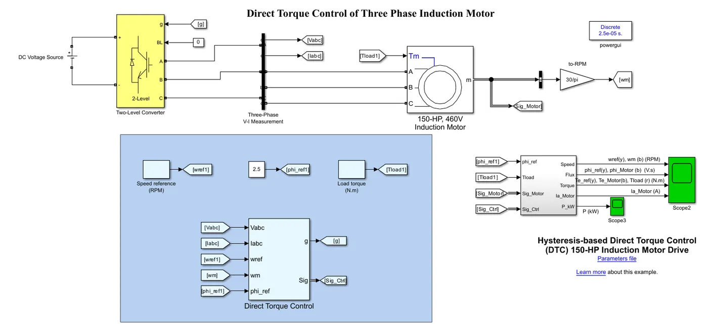
Figure 1. Simulink model of Three Phase Induction motor Drive using Hysteresis Based DTC
A DC voltage Source battery provides a 500 volt dc supply to the two level three phase inverter. A two level Voltage Source Inverter (VSI) is considered as a mature technology and becoming an industrial standard for the demand for energy saving. This 500 volt dc voltage converts into three phase ac voltage signal by means of this inverter with wide range of variable voltage magnitude and frequency. The types of used switches depends on the power of inverter and switching frequency. In the most applications, IGBT transistors with anti parallel diode are so helpful. The model of two level voltage source inverter is shown in figure 2.
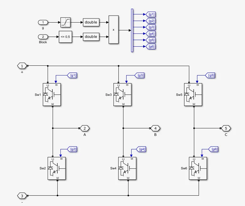
Figure 2. Two Level Three Phase Voltage Source Inverter
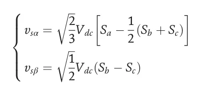
It consists of Six transistor switches S1-S6 and a constant DC Voltage Source Vdc connecting a three phase induction motor. The Voltage vector is generated by following equations:
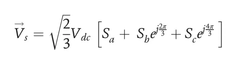
Where, Sa,Sb and Sc are the three phase inverter switching functions which can take a logical value of either 0 or 1.
The output of VSI is given to three phase induction motor with following parameters :
Motor Parameters:
- Stator Resistance = 0.5 Ohms
- Rotor Resistance = 0.2 Ohms
- Stator Leakage Inductance = 20 mH
- Rotor Leakage Inductance = 10 mH
- Magnetizing Inductance = 200 mH
- Number of Poles = 4
Thus, Synchronous Speed of Induction motor is given by
Ns = 120 * F / P
Here, P = Number of poles and equal to 4; F = Standard Frequency and equal to 60 Hz.
Ns = 120 * 60 / 4 = 1800 RPM
Fundamental Frequency (Ns) = 1800 RPM
In this simulation, we select a three phase induction motor of 150 HP, 460 Volt and following figure 3 shows the motor parameter set:
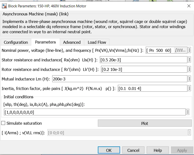
Figure 3. Induction Motor Design Parameter
As the induction motor gives the speed in RPS, we want to plot in RPM by connecting gain block whose value is 30/pi.
Here, we have given that the initial speed of motor is zero RPM. SO, we have added initial speed as zero and final speed is 1800 RPM into it by unit step block.The magnetic flux target is 2.5 Weber. The inital load torque is 0 Nm and final load torque is 50 Nm. This is shown in simulink model.
Principle of Direct Torque Control :
> DTC achieves a decoupled control of the Stator Flux and electromagnetic Torque in stationary reference frame ( alpha and beta) and it allows induction machines to have an accurate and fast electrodynamic torque response.
> It uses a switching table for selection of an appropriate voltage vector.
> The selection of switching states is related directly to the variation of stator flux and torque of the machine.
> Hence, the selection is made by restricting the flux and torque magnitudes within two hysteresis bands.
> Those controllers ensure a seperated regulation of both of these quantities.
> The inputs of hysteresis controller are the flux and torque errors as well as their outputs determine the appropriate voltage vector for each commutation period.
Figure 4 shows the subsystem of Direct Torque Control mechanism :
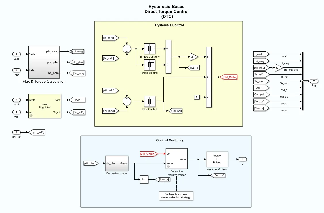
Figure 4. Conventional (Hysteresis Based) Direct Torque Control Subsystem
The main components of DTC subsystem are :
1) Flux & Torque Calculation.
2) Speed Regulation
3) Hysteresis Based DTC
4) Optimal Switching
1) Flux & Torque Calculation:
The stator flux linkage is estimated by the stator voltages & torque is calculated based on the estimated flux and motor currents.
i) Estimation of Stator Flux and Electromagnetic Torque :
The amplitude of stator flux is estimated from its two phase components Φs(Alpha) & Φs(Beta) :
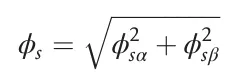 --------------------------------(I)
It requires the knowledge of the components of stator current vector Is(alpha) and Is(Beta) and that of vector stator voltage Vs(alpha) and Vs(Beta).
 ---------------------------------(2)
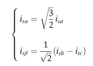 ------------------------------------------(3)
ii) Electromagnetic Torque Estimation:
The produced electromagnetic torque of induction motor can be determined using the cross product of stator quantities. i.e. Stator flux and stator currents. The torque formula is expressed as:
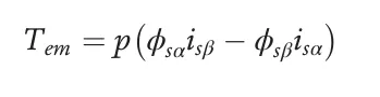 ------------------------(4)
Where, p = Number of pole pairs.
2) Speed Regulation : The regulator compares the actual motor speed with speed reference and generates the torque reference.
3) Hysteresis Based DTC :
The calculated flux magnitude and torque are compared with the reference values. When the resulting flux or torque error crosses either negative or positive hysteresis band values, a control signal is activated in order to correct the error.
i) Control of Stator Flux :
Based on the induction motor model in stationary frame, the stator flux equation can be expressed as follows:
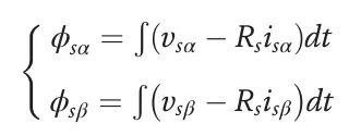 -----------------------------(5)
Considering that the control of switches of the inverter is done by control period or sampling Te and that each of these periods the states Sa, Sb and Sc are kept constant. the method of numerical integration of the rectangles make it possible to obtain expression of the sample K+1 of the stator flux in following form :
 --------------------------------(6)
The above equation 6 means that the stator flux can be changed by the application of stator voltage during a time K. The stator flux vector's extrimity moves in direction given by the voltage vector and making a circular trajectory.
> A two level hysteresis comparator is used for flux regulation. It allows to drop easily the flux vector extrimity within the limits of two concentric circles with close raduis.
> The choice of hysteresis bandwidth depends on the switching frequency of inverter.
Figure 5 shows the two level hysteresis comparator for stator flux control.
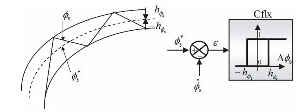
Figure 5. Two Level Hysteresis Comparator for Stator Flux Control
The logical outputs of flux controller are defines as:
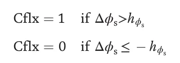 -----------------------------(7)
Where, hΦs = Hysteresis band of stator flux.
The stator flux error is defined by the difference between reference value of flux (Φ*) and actual estimated value (Φs):
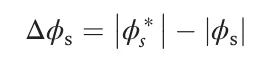 --------------------------------(8)
ii) Control of Electromagnetic Torque :
During one sampling period, the rotor flux vector is supposed invarient. The rotor and stator flux vectors are linked by the following relation:
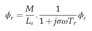 -------------------------(9)
The general expression of electromagnetic torque is given by :
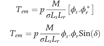 -----------------------(10)
where,
p = Number of pole pairs;
Φs & Φr = Stator and Rotor Flux Vectors respectively;
Del = Angle between stator and rotor flux vector.
From above equation 10, it is cleared that the electromagnetic torque is controlled by the stator and rotor flux amplitudes.
If those quantities are maintaing constant, the torque can be controlled by adjusting the load angle 'Del".
The torque regulation can be realized using three level hysteresis comparator.
Figure 6 shows the three level hysteresis comparator for electromagnetic torque control.
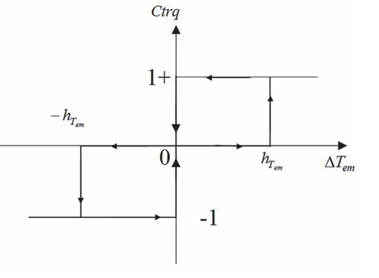
Figure 6. Three Level Hysteresis Comparator for electromagnetic torque control
where,
h(Tem) = Hysteresis band of torque.
The logical outputs of torque controller are defined as :
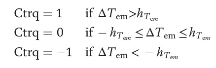 -----------------------------(11)
The torque error is defined as the difference between reference values of the torque and atual estimated values.
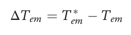 ------------------------------------------------(12)
4) Optimal Switching :
Pulses to motor inverter are produced based on the control signals generated by the hysteresis control and stator flux linkage position. The sectors of stator flux space vectors are denoted from S1 to S6. Stator flux modulus error after the hysteresis block ( Φ) can take just two values. The Torque error after the hysteresis block (Tau) can take three different values. The zero voltage vectors Vo and V7 are selected when the torque error is within the given hysteresis limits and must remain unchanged.
Figure 7 shows the strategy used to determine best voltage vector in each sector.
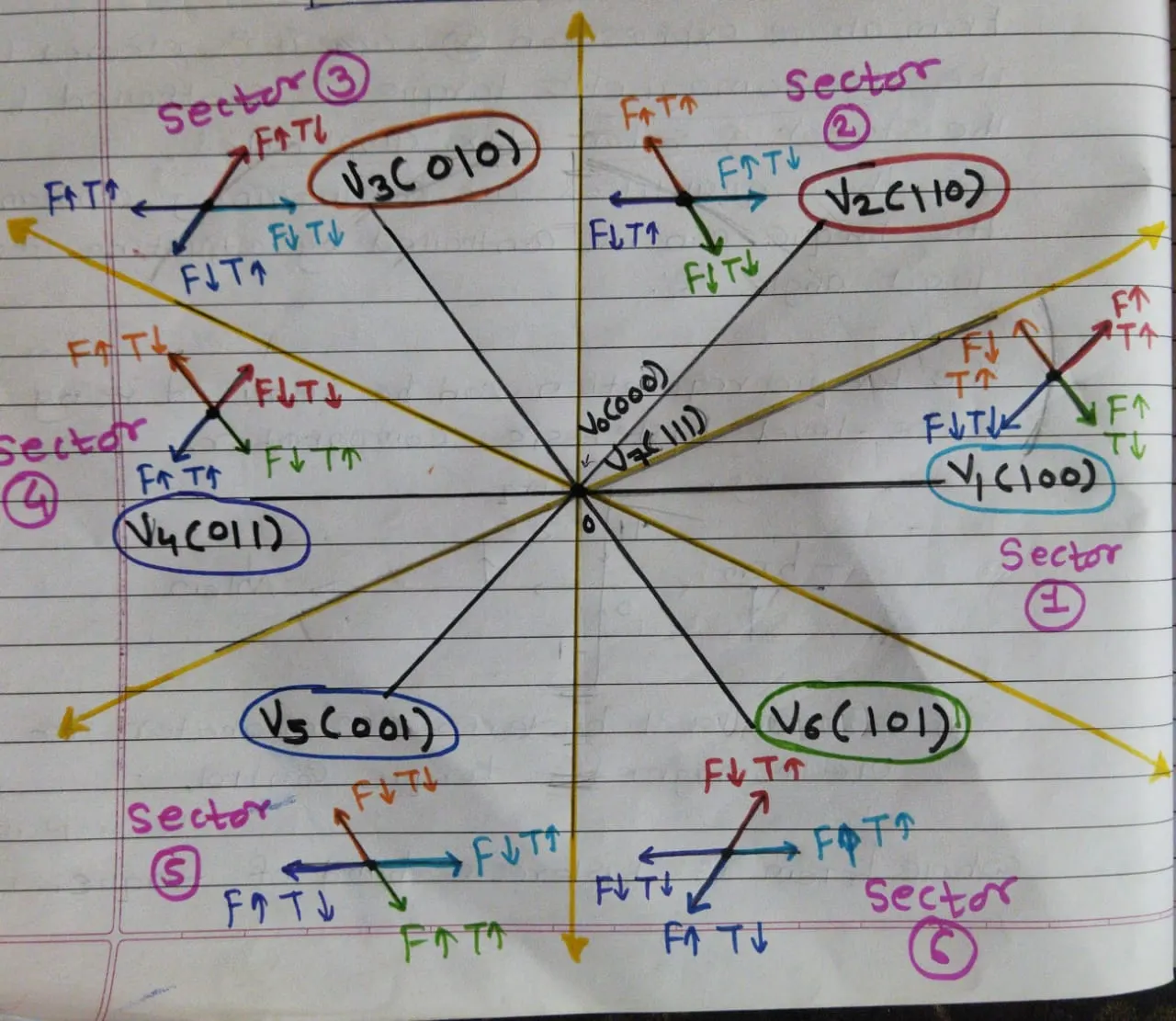
Figure 7. Strategy for voltage vector in each sector for two level Inverter
Figure 8 shows the Look-Up table for DTC of two level Inverter for controlling flux and torque.
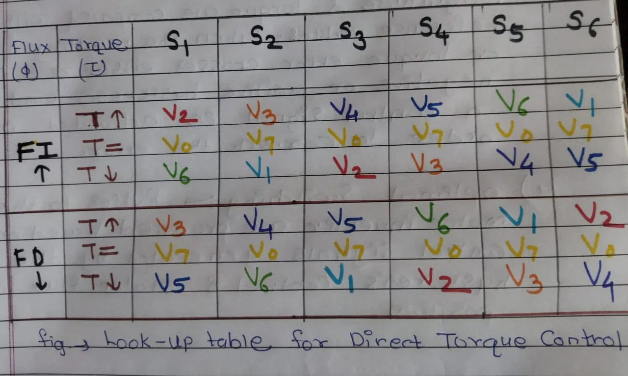
Figure 8. Look-Up Table for DTC of two level Inverter (Voltage Vector Selection Table for each Sector)
When we run above simulink model, we obtained following simulation results:
Simulation Result :
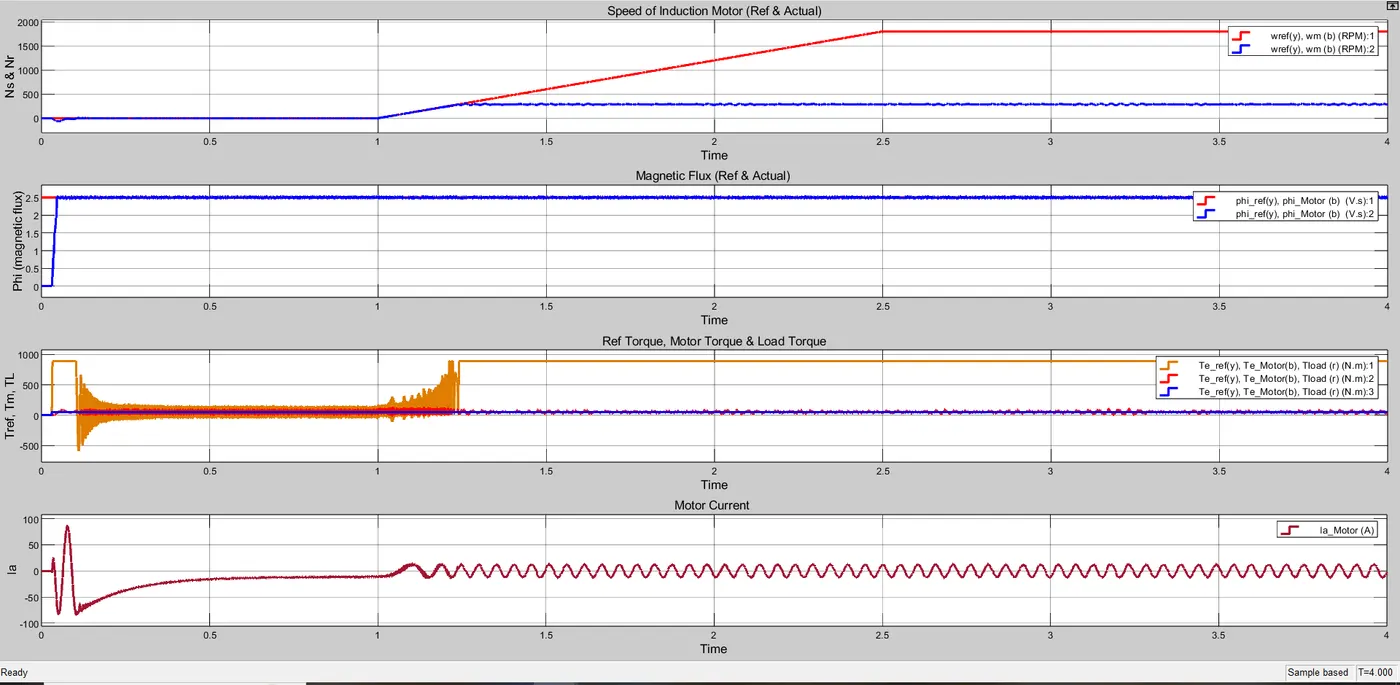
Figure 9. Speed, magnetic flux, torque and motor current waveforms of DTC (Zoom Out)
From figure 9,10 and 11, we observed that the first graph indicate the speed of motor in which two waveforms are present. One waveform indicate the reference speed and other indicate the actual speed of motor. Second graph indicate the magnetic flux which contain two waveforms one is reference and other is actual magnetic flux. Third graph contains three waveforms and it indicates reference torque, motor torque and load torque. Forth graph is about the motor current. The above graph shows the waveform for both initial and final speed of motor.
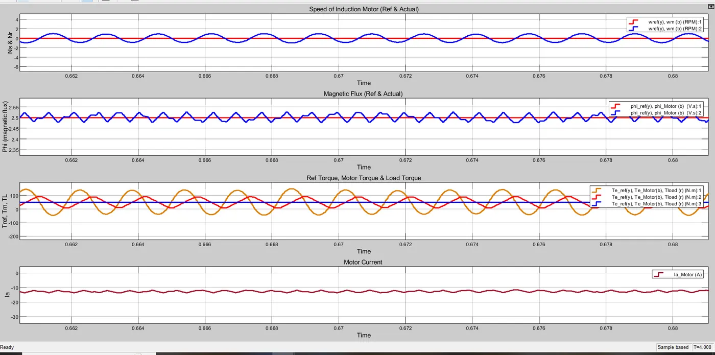
Figure 10. Speed, magnetic flux, torque and motor current waveforms of DTC at zero RPM speed of motor (Zoom In)
Figure 10 shows the zoom waveforms of above graphs for 0 RPM speed. From figure 10, we observed that the actual speed of the motor is zero and reference speed is also zero. In other word, the motor is at standstill condition. In design model, we already set the initital value of speed is zero and it is verified from above graph. The actual magnetic flux also follows the reference magnetic flux. The initial reference torque is set to zero hence the motor torque and load torque also follwos the reference torque. As the motor is at standstill condition, hence the motor current must be zero and fourth graph shown zero motor current.
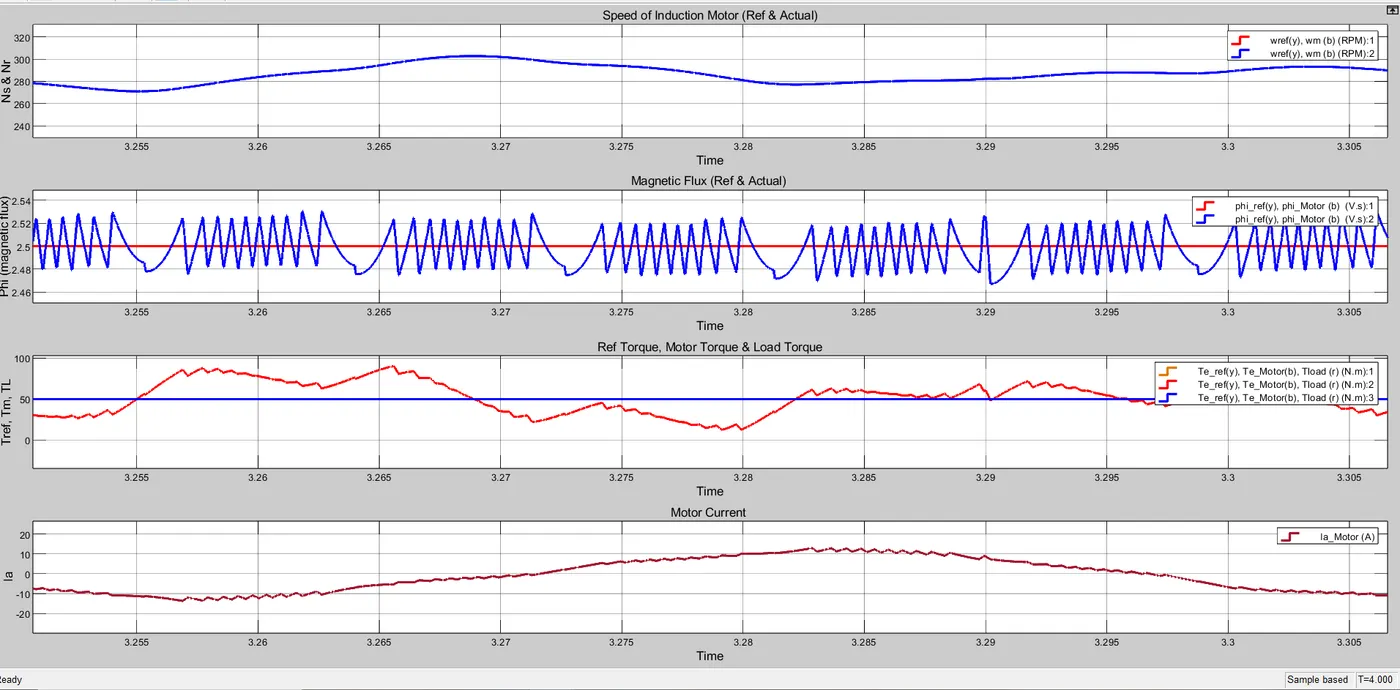
Figure 11. Speed, magnetic flux, torque and motor current waveforms of DTC when motor is running (Zoom In)
Above figure 11 shows the zoom waveforms of figure 9 when motor is running at some RPM value. Now, we have calculated the synchronous speed of motor previously and it is 1800 RPM. In first graph, the refernce speed of motor is 1800 RPM (Not shown in zoom waveform). We know that the motor always run below synchronous speed. Hence, we have seen that the actual speed of motor is near about 280 to 290 RPM. There are some magnetic flux variation in second waveform but it is very small and negligible. The motor torque follows the load torque but there is some variations in motor torque. The motor current is near about 10 ampere when motor is in running condition.
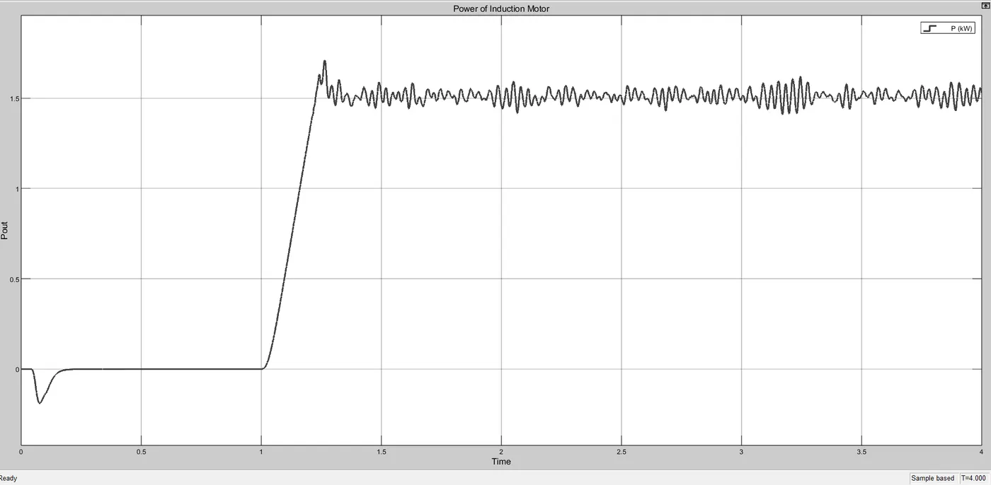
Figure 12. Electric Power (kW) Waveform of three phase induction motor
Figure 12 shows the electric power waveform of three phase induction motor, we observed that when the intital speed of motor is zero, the power consumption of motor is also zero. When the speed of motor increases the power consumption mot motor is also increases. When the motor runs at 290 RPM, the power consumed by the motor is 1.5 kilo-Watt.
Conclusion:
In this way, we have successfully studied and simulate the three phase induction motor drive using V/F control method and DTC control method.