Project 2 - Modeling of 3 phase Induction Motor Drive
| Project 2 - EV Application of Induction Motor |
___Q1___
AIM : Open Loop speed control of 3 phase Induction Motor using V/F method.
THEORY :
- Three phase Induction Motor (IM) produces Rotating Magnetic Field (RMF) rotating at Synchronous Speed (`N_s`).
- `N_s = (120*f)/P`
- EMF induced in IM is given by, `V\ \=\ \4.44*f*phi*K*T`.
- Where f = Fundamental Frequency; P = Number of Poles; T = number of turns per phase;
- Flux induced is given by, `phi\ \=\ \V/(4.44*f*K*T)`
- Now if frequency is changes, synchronous speed also changes; but with decrease in frequency flux will increase .
- This change in flux causes saturation or rotor and stator core which causes increase in NL current of motor.
- So, to maintain the flux constant, applied voltage (V) needs to be changed.
- Thus, decrease in frequency causes flux to increase but at the same time if voltage is decreased flux decreases, causing no change in flux.
- Hence by keeping V/F constant, speed is changed.
DESIGN PARAMETER :
- 3 phase squirrel cage IM.
- Power = 100 HP.
- DC Voltage = 800 V.
- Switching Frequency = 10 kHz.
- Output Voltage = 460 VRMS – line to line.
- Initial Speed = 1500 RPM.
- Final Speed = 1000 RPM.
- Initial Load Torque = 10 Nm.
- Final Torque=20 Nm.
- Torque Step Time = 0.1 secs.
SIMULINK MODEL :
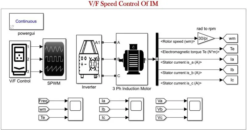 |
Each block is explained below :-
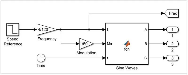
1 - V/F Control :
 |
|
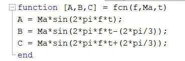
- Matlab Function Block
|
 |
|
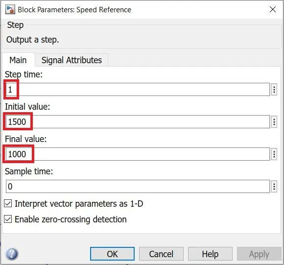
- Frequency input is taken by converting Input Speed - This model uses 4 pole motor. - Speed Reference is simulated by Step block. - Step/speed changes from 1200 to 1000 at 1 second. - Modulation Index represents V/F i.e. 1/F |
|
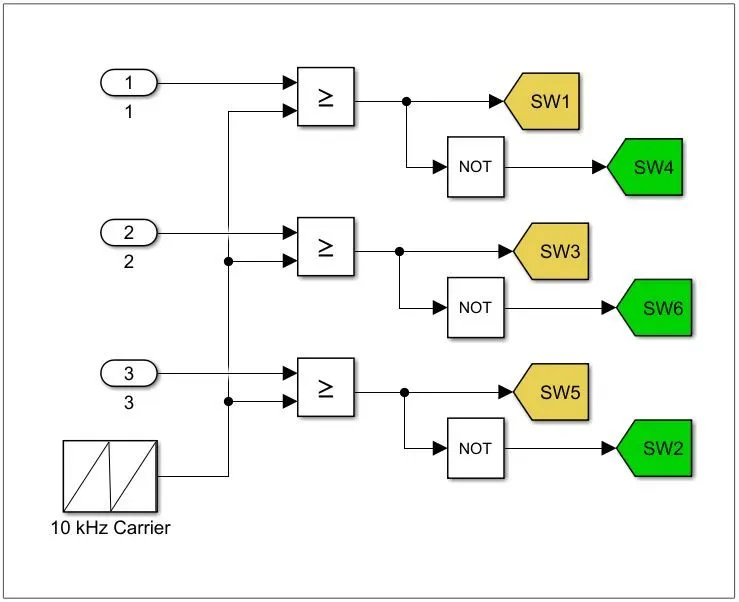
2 - SPWM
|
- Sine Pulse Width Modulation
|
 |
3 - Inverter
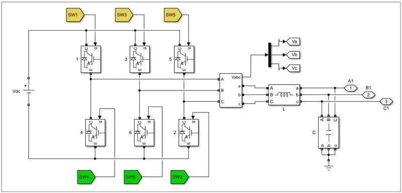 |
| - | DC Voltage Source with 800 V as input is given to Inverter. | |
| - |
6 IGBT switches are used to create a 3 phase inverter. Each is triggered by gate pulses from SPWM taken via from block. |
|
| - |
Three phase VI Measurement block is used to measure inverter phase |
|
| - |
Filter Design : `L < (0.03*V_(i\n))/(2*pi*f*I_(Lmax))` `C = 1/((2*pi*f)^2 *L)` `L = 80\ \muH` `C = 11.9\ \mF` |
4 - Three Phase Induction Motor.
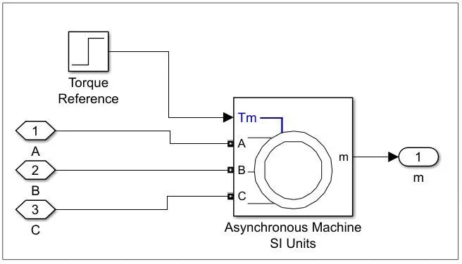 |
- Asynchronous Machine block set as model : 05 100 HP 460V 60Hz 1780 RPM with Squirrel Cage.
- Torque reference is modelled using a step block, wherein at 0.1 second torque changes from 10 Nm to 20 Nm.
RESULTS :
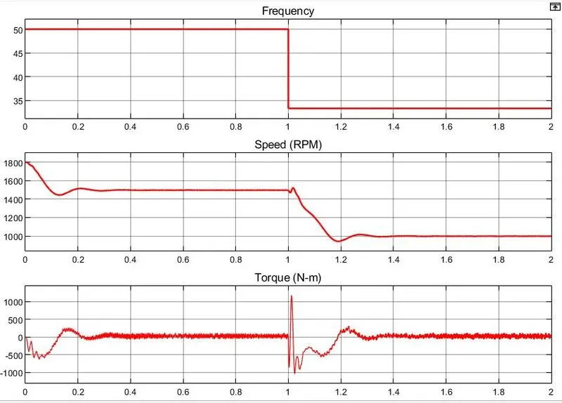
- Plot below shows Frequency, Speed and Torque of the IM.
- As seen frequency changes from 50 Hz to 33 Hz at 1 second.
- Speed first settles at 1500 rpm from 1800 rpm after intial ringing, at 1 second the speed changes to 1000 rpm and thus to keep the flux constant, frequency also steps downs.
 |
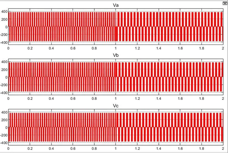
Plot below shows Stator Voltages
 |
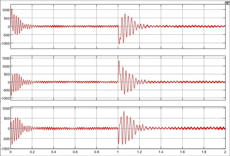
Plot below shows Phase currents.
After initial transients the current settles to nomial value.
 |
___Q2___
AIM : To derive the Transfer Function of 3 phase Induction Motor.
THEORY :
Circuit Diagram below shows the equivalent model of IM where rotor referred to stator side.
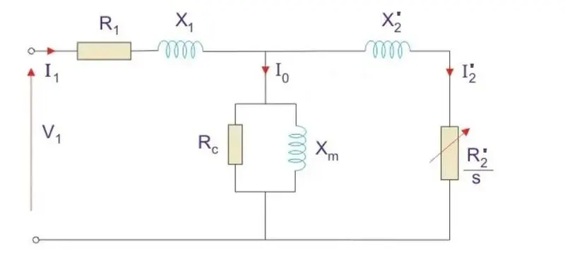 |
where,
`V_1 =`Stator Voltage
`R_1 =`Stator Resistance
`X_1 =`Stator Leakage Reactance
`I_1 =`Stator Current
`R_c =`Shunt Branch Resistance
`X_m =`Magnetising Reactance
`I_o =`Per phase NL current
`R_2' =`Rotor Resistance referred to Stator
`X_2' =`Standstill Rotor Reactance referred to Stator
`I_2' =`Rotor Current per phase referred to Stator
s = Slip
Equation of Electrical Machine is given by,
`V_a = I_aR_a\ \+\ \jX_sI_a\ \+\ \E_b`
Taking Laplace Transform
`V_a(s) = I_a(s)(R_a\ \+\ \jX_s)\ \+\ \E_b(s)`
Back EMF `E_b = K_tstheta(s)`
putting in equation above
`V_a(s) = I_a(s)(R_a\ \+\ \jX_s)\ \+\ \K_tstheta(s)`
rearranging,
`I_a(s) = (V_a(s)\ \-\ \K_tstheta(s)) / (Z(s))`
Electrical Torque is givne by,
`T_e = (KE^2R)/(R^2+X^2)`
Taking Laplace Transform
`T_e = E^2sintheta`
Similarly, Mechanical Torque is given by,
`T_m = Jddottheta\ \+\ \Btheta`
Taking Laplace Transform
`T_m(s) = (Js^2\ \+\ \Bs)theta(s)`
`T_m = T_e`
`E^2theta(s) = Js^2\ \+\ \Bs(theta(s))`
`(Js^2\ \+\ \Bs\ \-\ \E^2)theta(s)\ \=\ \T_m`
rearranging,
`(Js^2\ \+\ \Bs\ \-\ \E^2)\ \=\ \T_m/(theta(s))`
`(theta(s))/T_m = 1/ ((Js^2\ \+\ \Bs\ \-\ \E^2))`
`T\ \prop\ \phiI_acostheta`
putting `theta = 0`
`T = KphiI_a`
Taking Laplace Transform
`T = Kphi(s)I_a(s)`
Equating both T and putting value of `I_a`
`K_aV_a(s) = (Js^2\ \+\ \Bs\ \-\ \E^2)theta(s)Z(s)\ \+\ \K_tstheta(s)`
Rearranging,
`(Output)/(Input) = (theta(s))/(V_a(s)) = (K_a)/((Js^2\ \+\ \Bs\ \-\ \E^2)Z(s)\ \+\ \K_aK_ts)`
Transfer Function = `(Output)/(Input)`
| `(theta(s))/(V_a(s)) = (K_a)/(JL_as^3\ \+\ \(R_aJ\ \+\ \BL_a)s^2\ \+\ \(BR_a\ \+\ \K_aK_t)s)` |
___Q3___
AIM : To Model 3 phase induction motor with a 3 phase inverter using Direct Torque control using an Average Model.
THEORY :
Variable frequency drives control AC induction motors through one of several control schemes. Scalar control (V/f control) varies both the voltage and frequency of power supplied to the motor to maintain a fixed ratio between the two. This keeps the strength of the magnetic field at a constant level so that torque production remains stable. Scalar control is a simple, inexpensive control method, but it doesn’t allow precise control of motor speed.
Vector control (FOC) controls the magnetizing and the torque-producing components of the stator current independently to control both motor speed and torque.
Another control method, known as direct torque control (DTC), is similar to field oriented control, in that it decouples torque and flux and controls them independently. But DTC controls motor torque directly, without a modulator, so torque response is much faster.
The principle of DTC is based on the direct application of a control sequence to the switches of the voltage inverter .
The choice of this sequence is made by the use of a switching table and two hysteresis regulators whose role is to control and regulate the electromagnetic torque and the flux of the machine in a decoupled manner.
The electromagnetic torque is controlled using a three level hysteresis comparator.
While the stator flux is controlled using a two level hysteresis comparator.
The outputs of these comparators, as well as the flux vector information, are used to determine the switching table.
SIMULINK MODEL :
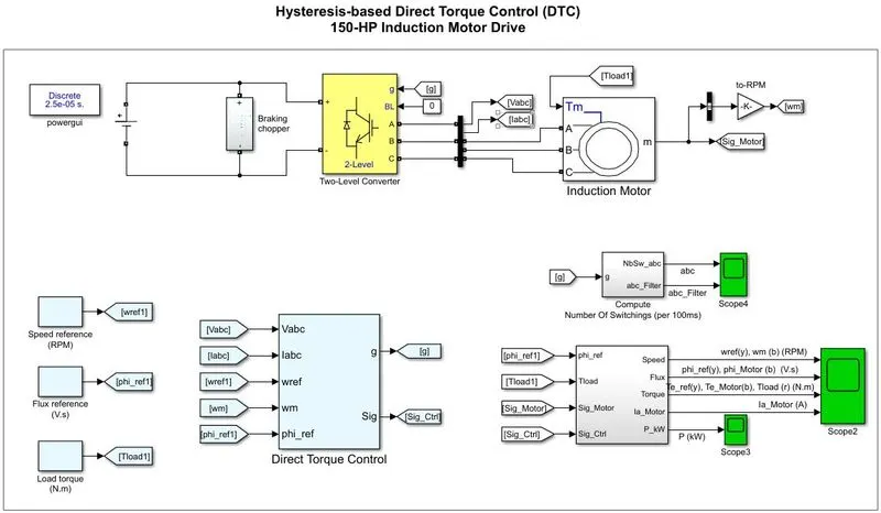 |
Electrical Model
The electrical energy is supplied by DC Voltage Source. In addition, a braking chopper is connected to the DC bus in order to dissipate the kinetic energy of the motor during deceleration.
An inverter-fed induction motor drive can be controlled through various techniques depending on application, desired performance, and controller design complexity. Commonly used schemes are scalar control (V/Hz control or open loop flux control) or vector control (field-oriented control or direct torque control). This example uses a hysteresis-based direct torque control (DTC) technique.
Direct Torque Controller
Direct torque control (DTC) is a technique that allows you to instantaneously control the motor magnetic flux and its electromagnetic torque in a decoupled way. Controlling the torque directly permits accurate static and dynamic speed regulation. The main components of the DTC subsystem are:
-
Flux and Torque Calculation — The stator flux linkage is estimated by integrating the stator voltages, and torque is calculated based on the estimated flux and the motor currents.
-
Speed Regulator — The regulator compares the actual motor speed with the speed reference and generates the torque reference.
-
Hysteresis Control — The calculated flux magnitude and torque are compared with the reference values. When the resulting flux or torque error crosses either the positive or negative hysteresis band value, a control signal is activated in order to correct the error.
-
Optimal Switching — Pulses to the motor inverter are produced based on the control signals generated by the hysteresis control and the stator flux linkage position.
DESIGN PARAMETER :
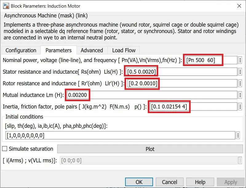
1. Induction Motor.
|
 |
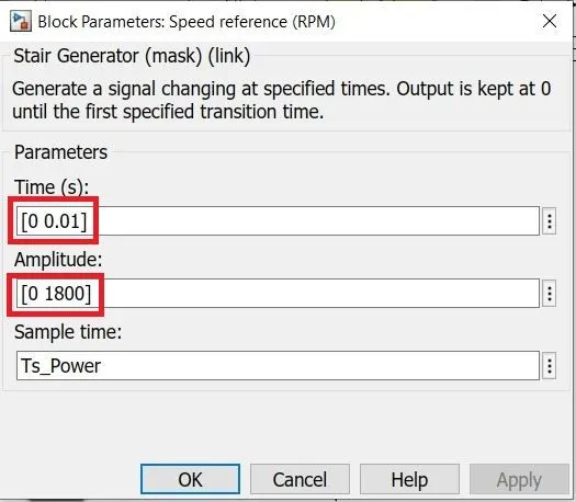
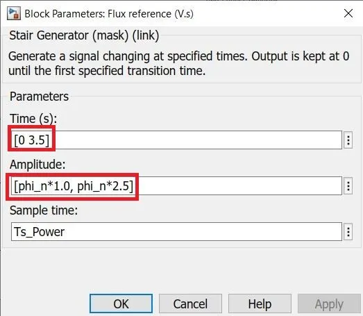
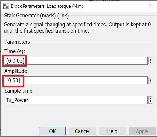
2. Speed Reference, Flux Reference, Load Reference
 |
 |
 |
OBSERVATIONS :
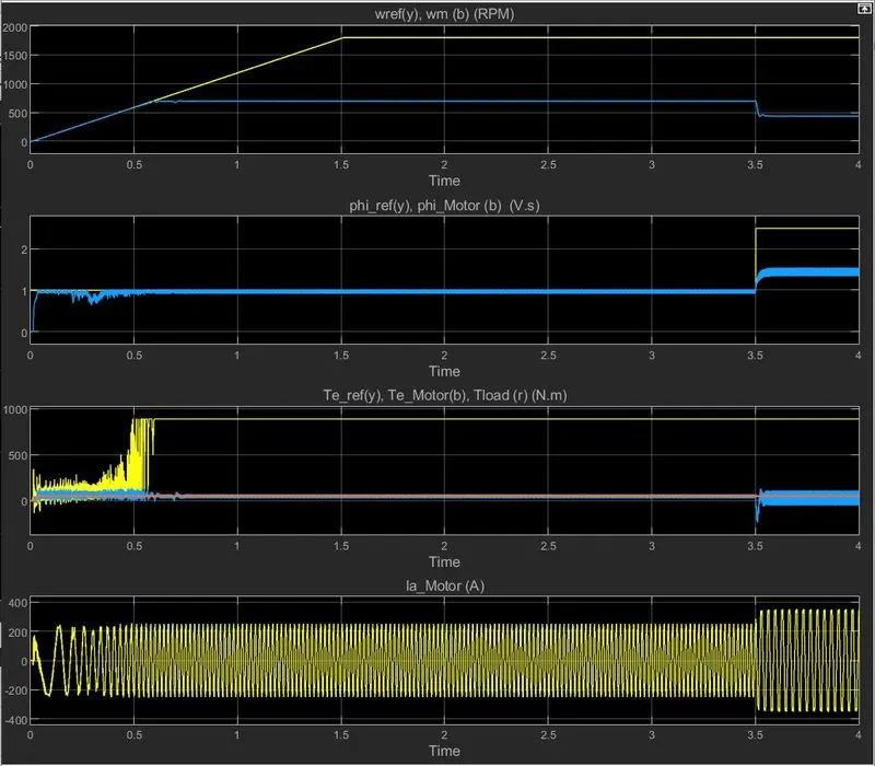
- The speed reference is set to 1800 rpm, but the achieved speed is only 700 rpm.
- The targerted flux of 2.5 Weber could not be achieved.
- Load torque of 50 Nm is achieved successfully.
 |
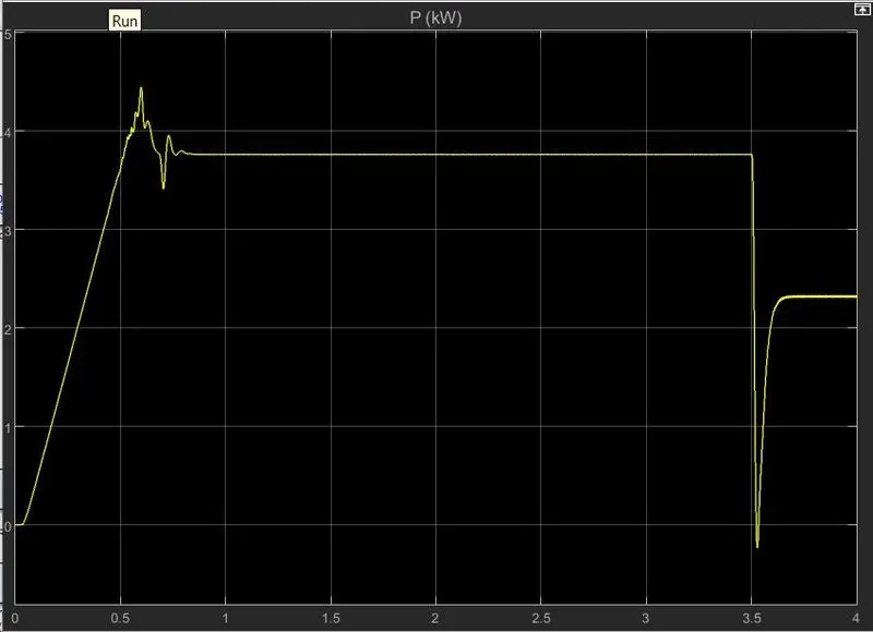
Power Output : 3.76 kW of power is achieved.
 |
CONCLUSION :
| 1. | V/F control of 3 phase Induction Motor is successfully simulated with frequency changing from 50 Hz to 33 Hz at the set point to achieve change in speed. |
| 2. | Transfer Function of 3 phase Induction Motor is successfully derived. |
| 3. | Direct Torque Control of 3 phase Induction Motor could not be carried out satisfactorily. |