Project 2 - Modeling of 3 phase Induction Motor Drive
TITLE = Modeling of 3 phase Induction Motor Drive.
Q 1) Model 3 Phase Inverter using Simulink (model the parasitic as well) with a switching frequency of 10Khz using 3 phase Squirrel Cage Induction motor, using V/F method, open loop
Design Parameters:
- Power = 100 HP
- DC Voltage = 800 V
- Output Voltage = 460 VRMS – line to line
- Initial Speed = 1500 RPM
- Final Speed = 1000 RPM
- Initial Load Torque = 10 Nm
- Final Torque=20 Nm
- Torque Step Time = 0.1 secs
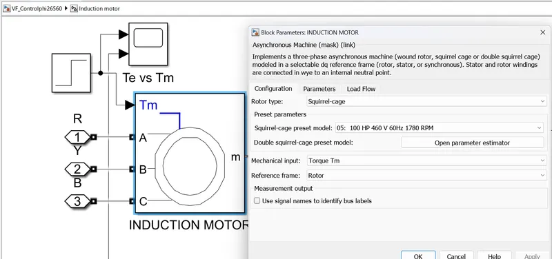
For Induction Motor model – use Asynchronous Machine from Simulink with Squirrel Cage Preset Model – 05 , for 100HP Motor
For back emf to speed relation, assume a linear rate from 0.25 to 1, with speed changing from 500 RPM to 2000 RPM
Plot speed, stator voltage (line to line) and frequency.
Plot stator line voltage, phase current.
=theory of V/F method-
The synchronous speed is given by,
Ns= 120*f/P
Thus, by controlling the supply frequency smoothly, the synchronous speed can be controlled over a wide range. this gives smooth speed control of an induction motor.
But the expression for the air gap flux is given by,
ɸg = (1/4.44*K1*Tph1) *(V/f)
this is according to the e.m.f. equation of a transformer. Where,
K1 = Stator winding constant
Tph1 = Stator turns per phase
V = Supply voltage
f = Supply frequency
it can be seen from this expression that if the supply frequency f is changed, the value of air gap flux also gets affected. This may result into saturation of stator and rotor cores. Such a saturation leads to the sharp increase in the (magnetisation) no load current of the motor. Hence it is necessary to maintain air gap flux constant when the supply frequency f is changed.
To achieve this, it can be seen from the above expression that along with f, V also must be changed so as to keep (V/f) ratio constant. This ensures constant air gap flux giving speed control without affecting the performance of the motor. Hence this method is called V/f control.
Hence in this method, the supply to the induction motor required is variable voltage variable frequency supply and can be achieved by an electronic scheme using converter and invertor circuitry.
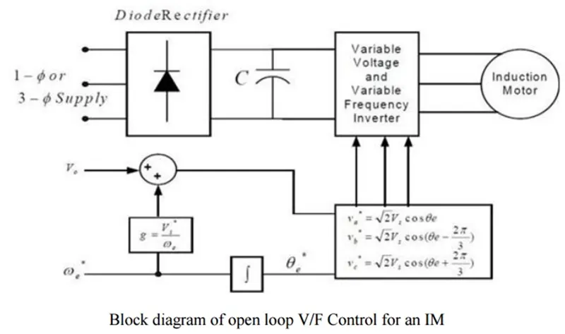
The normal supply available is constant voltage constant frequency a.c.supply.the converter converts this supply into a D.C. supply. this D.C. supply is then given to the inverter. The inverter is a device which converts D.C. supply, to variable voltage variable frequency A.C supply which is required to keep V/f ratio constant.
By selecting the proper frequency and maintaining V/f constant, smooth speed control of the induction motor is possible.
theory of 3 phase inverter=
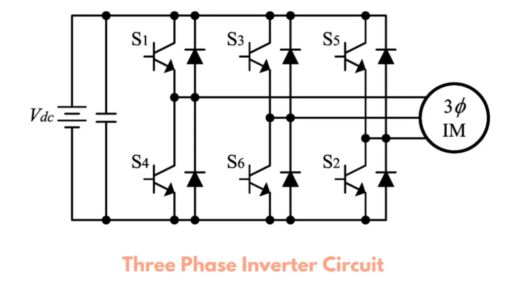
The main function of this kind of inverter is to change the input of DC to the output of three-phase AC. A basic 3 phase inverter includes 3 single phase inverter switches where each switch can be connected to one of the 3 load terminals.
Generally, the three arms of this inverter will be delayed with 120 degrees angle to generate a 3 phase AC supply.
The switches used in the inverter have 50% of ratio and switching can be occurred after every 60 degrees angle. The switches like S1, S2, S3, S4, S5, and S6 will complement each other. In this, three inverters with single-phase are placed across a similar DC source. The pole voltages within the three-phase inverter are equivalent to the pole voltages within the half-bridge inverter with a single phase.
Given design parameters:
- Power = 100 HP
- DC Voltage = 800 V
- Output Voltage = 460 VRMS – line to line
- Initial Speed = 1500 RPM
- Final Speed = 1000 RPM
- Initial Load Torque = 10 Nm
- Final Torque=20 Nm
- Torque Step Time = 0.1 secs
- Switching frequency = 10kHz
- Squirrel Cage Preset Model – 05 , for 100HP Motor
Simulink model of 3 Phase Inverter using Simulink (model the parasitic as well) with a switching frequency of 10Khz using 3 phase Squirrel Cage Induction motor, using V/F method, open loop
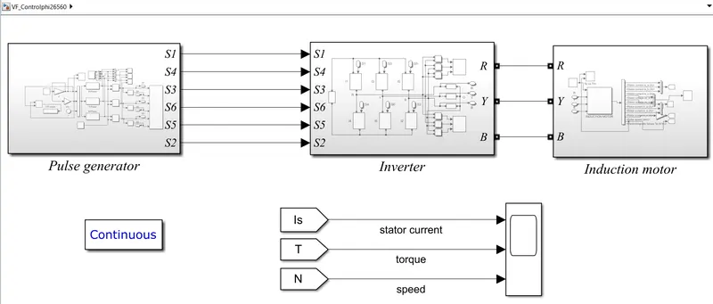
the model is designed in to three parts
1) SPWM (v/f control)
2) three phase inverter
3) three phase induction motor
1) SPWM (v/f control)
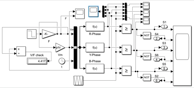
in this ,we considered switching frequency 10 KHz therefore
t= 1/10000
p=4 poles
F=60 Hz
phi=V/f=265/60
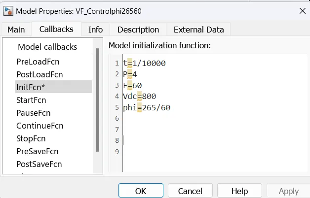
for V/F control method the motor speed in RPM is given as reference speed .
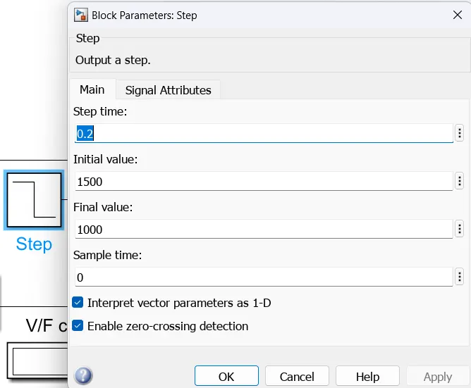
from above block it is clear that we select initial speed value is 1500 RPM and after 0.2 second it is 1000 RPM .
Ns=120*f/p
f= Ns*p/120
These reference speed when multiplied by P/120 then it gives the new frequency.
the frequency ,Vm and clock signal are given as input to bus creator
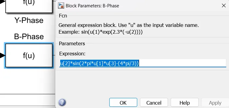
the bus creator output is given to the MATLAB function block and the phase voltages are measured by using the below formulae
Vr= Vm*sin(2*pi*f*t)
Vb = Vm*sin((2*pi*f*t)-(2*pi/3))
Vc = Vm*sin((2*pi*f*t)-(4*pi/3))
these three sin waves are displaced by 120 degree from each other as shown above.
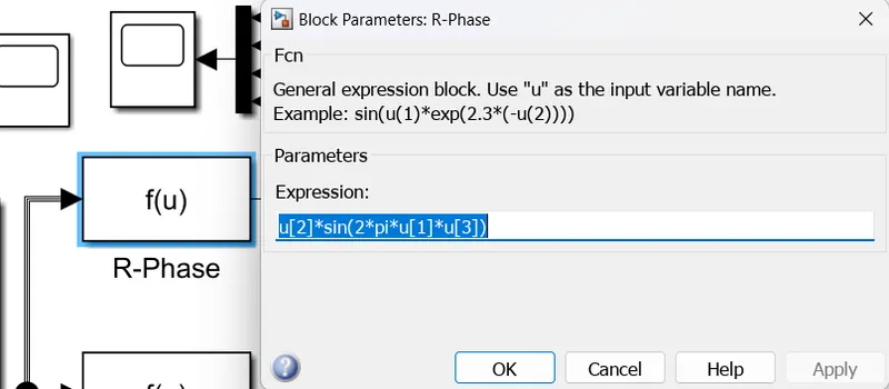
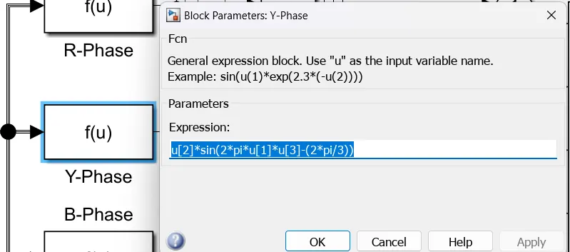
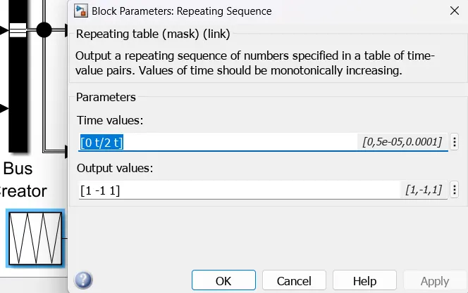
A repeating Sequence block is used to generate triangular wave. This Triangular wave is compared with 3 sine waves by using relational operator.
When Sinewave output is greater than Triangular wave then the high gate pulse is generated. A NOT gate is used to generate the opposite gate pulse. These gate pulses are then given to three phase inverter IGBTs. The gate pulses generated from NOT gate is connected to bottom phase of inverter.
2) three phase inverter
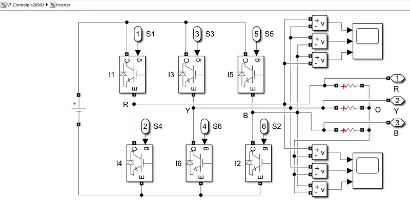
in this subsystem ,the DC voltage source is taken as input .
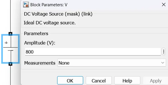
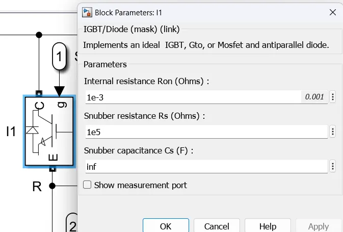
This voltage is given to the IGBT switch. The inverter has 3 legs with each leg having 2 number of Power Switching device IGBT. These 6 Power switches will operate for both high (positive signal) and low(negative) Signal operation. The Gate Signals for Switches is generated by using V/F Control Method. A voltage measurement block is used to measure the Line-to-Line voltage and Line to Neutral Voltage.
by using scope we can observed waveforms of line to line and line to phase voltages.
the output of inverter is given to the induction motor and which is variable voltage and variable frequency supply.
3) three phase induction motor
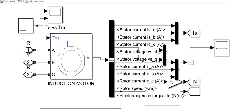
In this subsystem, the induction motor with torque input is observed.
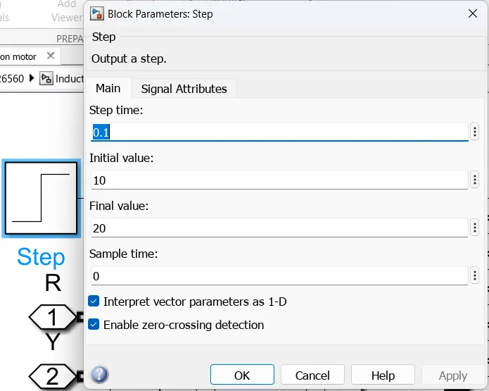
For the induction motor is connected to the 3-phase inverter with an input supply and for the motor toque input ,a step block with torque input values are taken.
At initial 10 NM of torque is applied and the torque increases to 20 NM.
For this induction motor,asynchronous machine block is used with parameters 100 HP,460 V,60 Hz,1730 RPM squirrel cage rotor motor.
the induction motor measurement port is connected to bus selector .
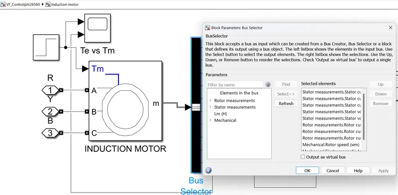
To observe the motor stator current, speed, and torque parameters a bus selector block is connected to the Induction motor measurement block and parameters are selected. Then the stator current and torque are given to scope, the rotor speed is multiplied with a gain block 60/2*pi, and it was given to scope.
RESULT =
1) Vm and f scope
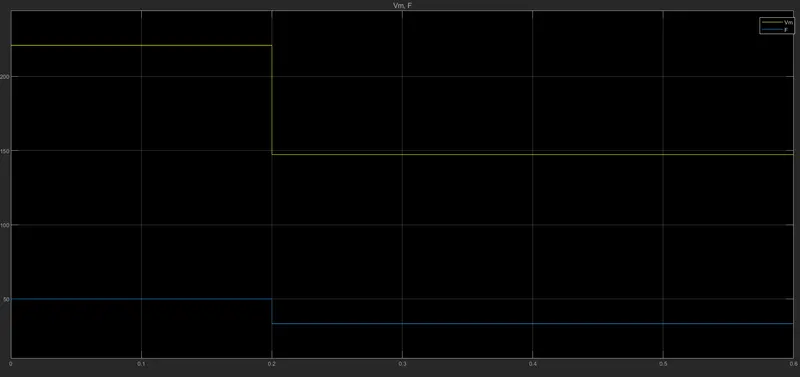
from above scope we can clear that , up to 0.2 second maximum volatage is 222 V and frequency is 50 Hz.
after 0.2 second , maximum volatage is 147 V and frequency is 33.33 Hz.
2) gate pulses
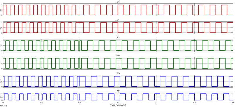
from first block ,pulses are generated and given to the inverter IGBT switch gate block.there are 6 gate pulses applied to the 6 IGBT switches.
3) stator line to line volatges
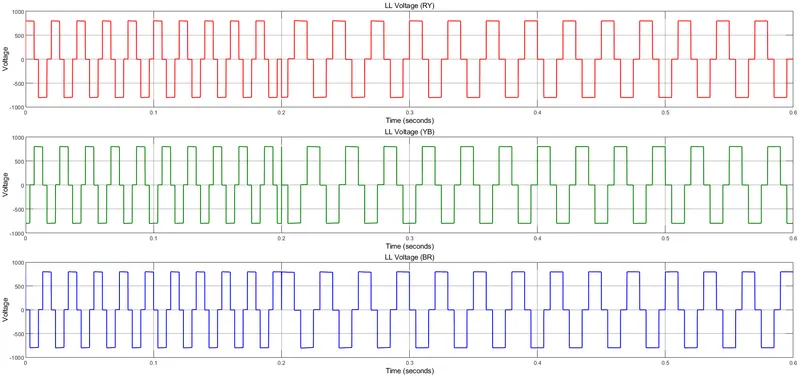
the outpur of the three phase inverter is line voltage or phase voltage.
this voltage is applied to induction motor.
line to line voltage magnitude varies from +800 TO -800 V.
4) phase to ground volatges
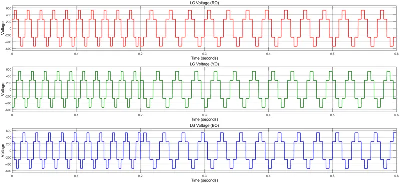
line to ground that is phase voltage varies from + 534 to -534 V.
5) stator current, torque and speed.
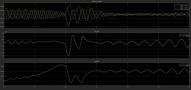
In above scope,the first plot is stator current ,second plot is torque and third plot is speed .
The speed is increased and reaches 1500 RPM at 0.2 seconds then after some oscillation the speed is decreased to 1000 rpm and maintained constant till 0.6 seconds.
from this small oscillation,there is oscillation present in stator current and torque waveform also.
Conclusion=
we can Modelled 3 Phase Inverter using Simulink (model the parasitic as well) with a switching frequency of 10Khz using 3 phase Squirrel Cage Induction motor, using V/F method, open loop and all results are plotted and explained.
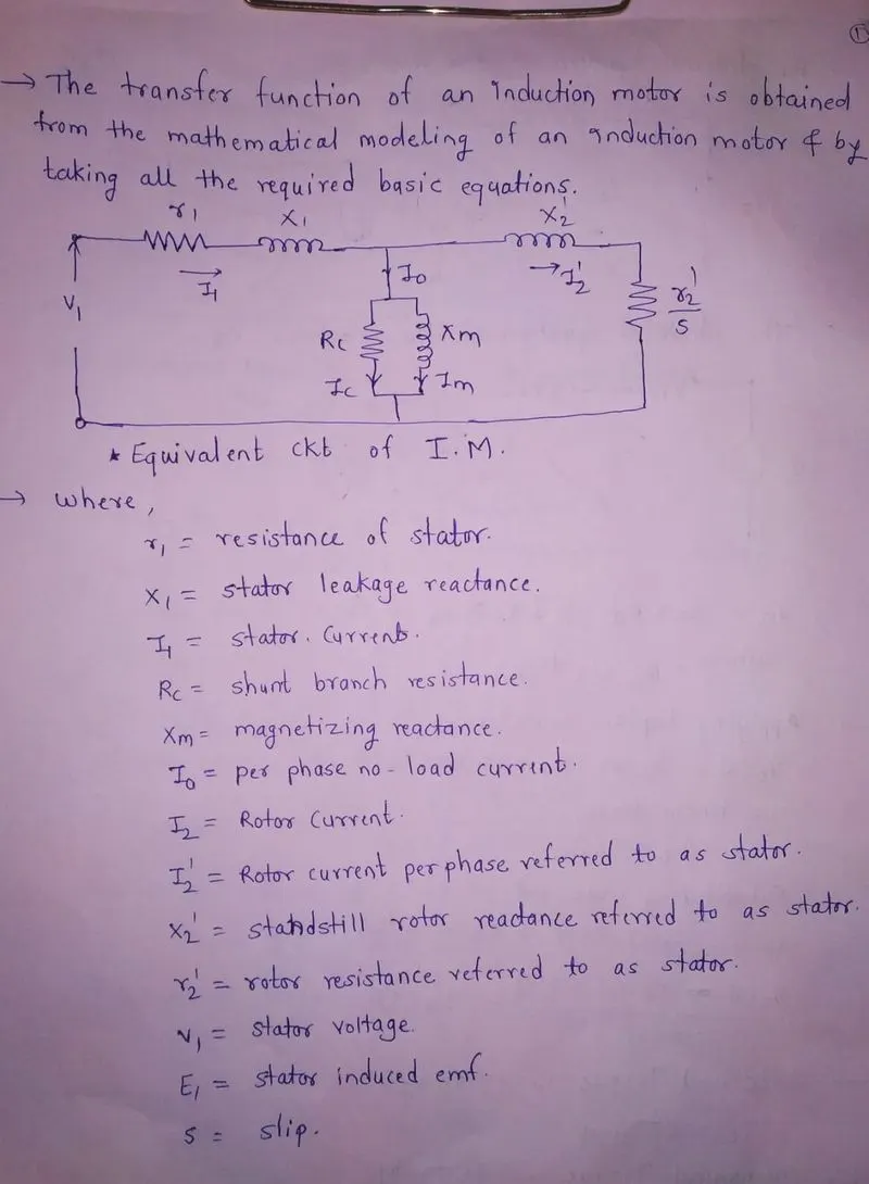
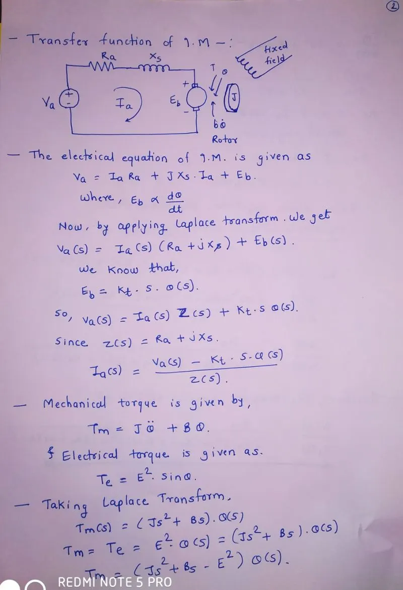
Q 2) Use the 3 phase inductor motor theory to derive the transfer function of 3 phase Induction Motor.
A 3-phase induction motor consists of a stator and a rotor.
Stator and rotor are electrically isolated and magnetically coupled like a transformer.so primary side is nothing but stator and secondary side is rotor.
For stator, three phase winding connected and the rotor carries a short-circuited winding called rotor winding,
The rotor winding drives its voltage and power from the stator winding through electromagnetic induction and hence the name induction motor.
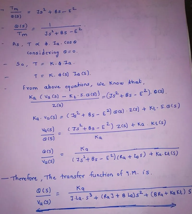
conclusion =
we derive the transfer function of 3 phase Induction Motor.
Q 3) Model 3 phase induction motor with a 3 phase inverter using Direct Torque control using an Average Model, Implement both torque and flux control to achieve desired power.
Design Parameters:
- Initial Speed = 0 RPM
- Flux Target = 2.5 webers
- DC Voltage = 500 V;
- Fundamental Frequency = 60 Hz
- Speed Step Time = 0.01 secs
- Determine fundamental speed based upon fundamental frequency
- Determine the switching sequence for direct torque control
- Moment of Inertia = 0.1 Kgm^2
- Load Torque Initial = 0 Nm
- Final Load Torque = 50 Nm
- Torque Step Time = 0.03 secs
Motor Parameters: (Create an Average Model)
- Stator Resistance = 0.5 Ohms
- Rotor Resistance = 0.2 Ohms
- Stator Leakage Inductance = 20 mH
- Rotor Leakage Inductance = 10 mH
- Magnetizing Inductance = 200 mH
- Number of Poles = 4
- Torque to Speed
=
DTC introduction
- DTC developed more than a decade ago by Japanese and German researchers (Takahashi and Noguchi 1984,1985).
- Drives with direct torque control (DTC) are being shown great interest since ABB has recently introduced a direct-torque -controlled induction motor drive, according to ABB can work even at zero speed.
- In a DTC drive, flux linkage and electromagnetic torque are controlled directly and independently by the selection of optimum inverter switching modes.
- The selection is made to restrict the flux-linkage and electromagnetic torque errors within the respective flux and torque hysteresis bands, to obtain fast torque response, low inverter switching frequency and low harmonic losses.
Main features of DTC (Direct torque control)
- Direct control of stator flux and electromagnetic torque.
- Indirect control of stator currents and voltages.
- Approximately sinusoidal stator fluxes and stator currents.
- Reduced torque oscillation
- Excellent torque dynamics
- Inverter switching frequency depending on flux and torque hysteresis bands.
Main advantages DTC (Direct torque control)
- Absence or co-ordinate transformations (which are required in most of the vector-controlled drive implementations)
- Absence of separate voltage modulation block (required in vector drives)
- Absence of voltage decoupling circuits (required in voltage source inverter-fed vector drives).
- Reduced number of controllers (e.q. only a speed controller is required if the drives contain a speed loop).
- The actual flux-linkage vector position does not to be determined but only the sector where the flux linkage is located.
To acquire high enactment, Direct Torque Control (DTC) is a technique used in AC drive systems. In this project, based on the hysteresis controller, a very simple improved DTC scheme is proposed for induction motor drive. Owing to its simple assembly & effective enactment, DTC is used for AC as well as DC drive as compared to other controlling schemes. this approaches mitigation of the ripples in torque by varying the predictable 3-level torque-hysteresis controller used in DTC. The expansion of distinctive switching approach has been generated for chosen voltage-vector. Based on ripple content simulation results carried out in MATLAB/SIMULINK for torque-hysteresis controller to minimize the ripples.
Simulink Model 3 phase induction motor with a 3 phase inverter using Direct Torque control
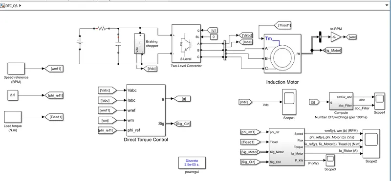
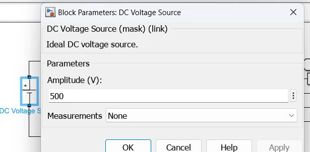
A 500 V DC is applied through braking chooper to the inverter.
A brake chopper is used to monitor the DC link voltage in a frequency inverter. This monitoring is necessary because power surges can occur in the intermediate circuit.
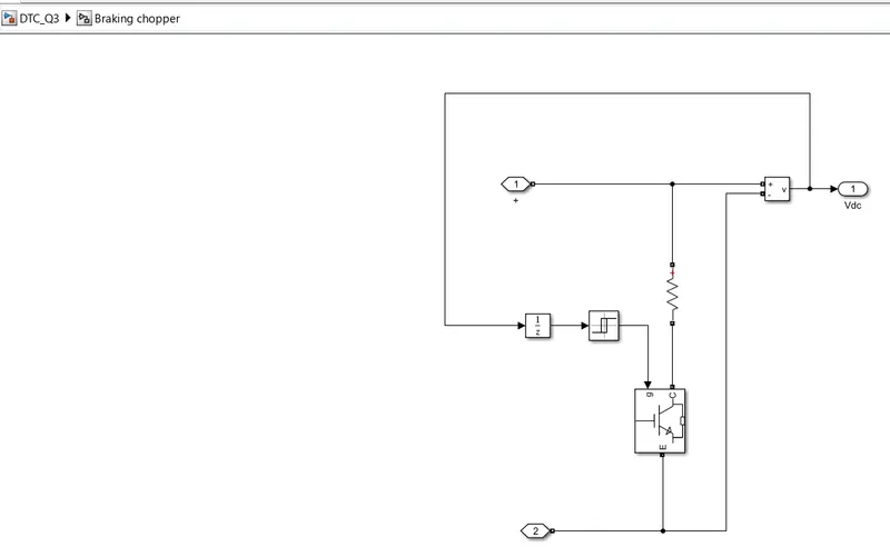
The dual chopper operates in a three-in-one system: in the first mode, the batteries charge at high rates; the second mode controls the amount of power flowing from battery to motor; and in the third or regenerative braking mode, the chopper transfers energy from the motor to the battery.
Then this DC supply is applied to two level converter.
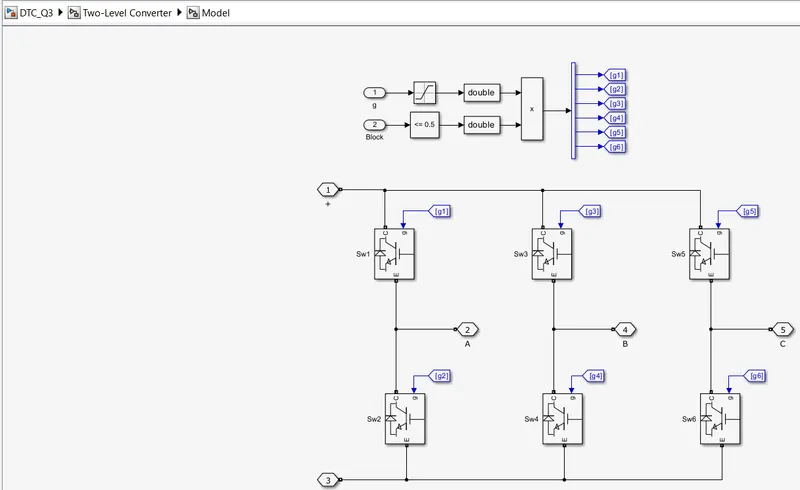
the output of this inverter is variable volatage variable frequency as per gate pulses applied to inverter.
The outputs from these two-level controllers are updated every 25 microseconds to indicate whether torque or flux needs to be changed. Depending on the outputs from the two-level controllers, the switching logic directly determines the optimal positions of the inverter switches. That's why everyone the voltage pulse is determined separately at the "atomic level". The inverter switch positions again determine the motor voltage and current, which in turn affect torque and motor flux and the control loop is closed.
the output of inverter is three phase supply is applied to 3 phase induction motor.
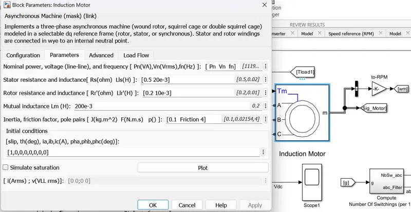
the output of induction motor is speed which is in RPM and compred with speed reference for getting accurate result.
An inverter-fed induction motor drive can be controlled through various techniques depending on application, desired performance, and controller design complexity. Commonly used schemes are scalar control (V/Hz control or open loop flux control) or vector control (field-oriented control or direct torque control). This example uses a hysteresis-based direct torque control (DTC) technique.
Direct Torque Controller
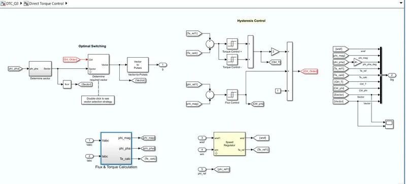
It is a technique that allows you to instantaneously control the motor magnetic flux and its electromagnetic torque in a decoupled way. Controlling the torque directly permits accurate static and dynamic speed regulation. The main components of the DTC subsystem are:
- Flux and Torque Calculation — The stator flux linkage is estimated by integrating the stator voltages, and torque is calculated based on the estimated flux and the motor currents.
- Speed Regulator — The regulator compares the actual motor speed with the speed reference and generates the torque reference.
- Hysteresis Control — The calculated flux magnitude and torque are compared with the reference values. When the resulting flux or torque error crosses either the positive or negative hysteresis band value, a control signal is activated in order to correct the error.
- Optimal Switching — Pulses to the motor inverter are produced based on the control signals generated by the hysteresis control and the stator flux linkage position.
The figure below illustrates the strategy used to determine the best voltage vector when the flux linkage is located in sector 0.
The image shows four cases:
- V3 is selected when the electromagnetic torque should be increased and the flux should stay unchanged. Selecting the V3 voltage vector speeds up the flux and thus applies an acceleration torque to the rotor while slightly decreasing the flux magnitude.
- V2 is selected when the electromagnetic torque should be increased and the flux should be increased. Selecting the V2 voltage vector slightly speeds up the flux and increases its magnitude.
- V6 is selected when the electromagnetic torque should be reduced and the flux should be increased. Selecting the V6 voltage vector slows down the flux and thus applies a deceleration torque to the rotor while increasing the flux magnitude.
- V5 is selected when the electromagnetic torque should be reduced and the flux should stay unchanged. Selecting V5 the voltage vector applies a deceleration torque to the rotor and slightly decreases the flux magnitude. Note that voltage vectors V1 and V4 are not selected in sector 0. Using these two vectors would have too much negative impact on the desired flux value. Finally, to keep the torque and the flux unchanged, the null voltage vectors V0 or V7 are selected.
When the flux linkage vector moves to sector 1, the selected voltage vectors become V4 for case 1, V3 for case 2, V1 for case 3, and V6 for case 4, and vectors V2 and V5 are not used. This 60-degree shift in the voltage vectors happens each time the flux linkage vector enters a new sector.
flux and torque calculation
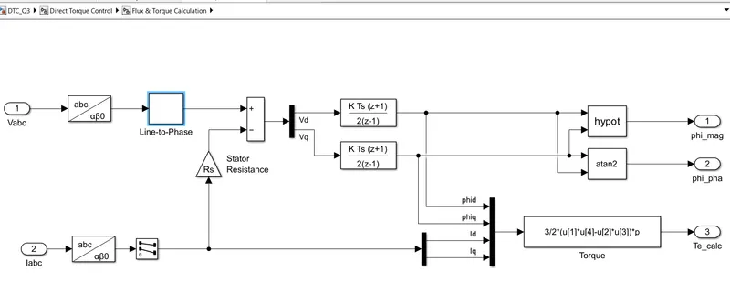
The stator flux linkage is estimated by integrating the stator voltages, and torque is calculated based on the estimated flux and the motor currents.
The 3phase Voltage and 3 phase current is converted from abc to Alpha-Beta-Zero and are given as input to Transfer function block. From two abc to Alpha-Beta-Zero blocks three output signals are created which are Phase magnitude, Phase angle and Torque.
we calculate torque by using formula
Te= (3/2)*P*((sci(ds)*Iqs - sci(qs)*Ids))
Speed regulator
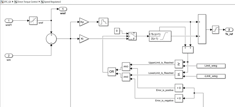
in this actual motor speed wm is compared with reference speed and from we generates reference torque .
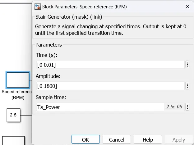
as per given in question step time is 0.01 second and we assumed the speed is 1800 RPM.
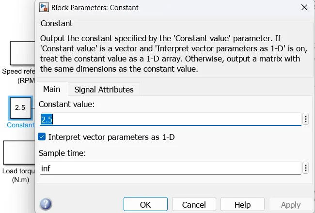
reference flux target value is 2.5 webers.
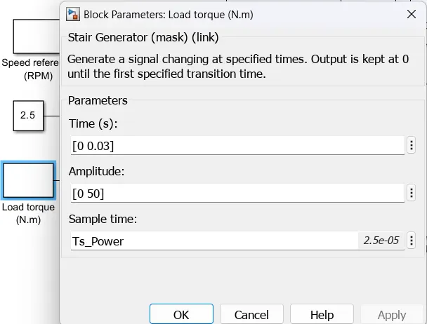
as per given step time of torque is 0.03 second.
initial value of torque is 0 Nm.
final value of torque is 50 Nm.
SCOPE RESULT
1) Vdc
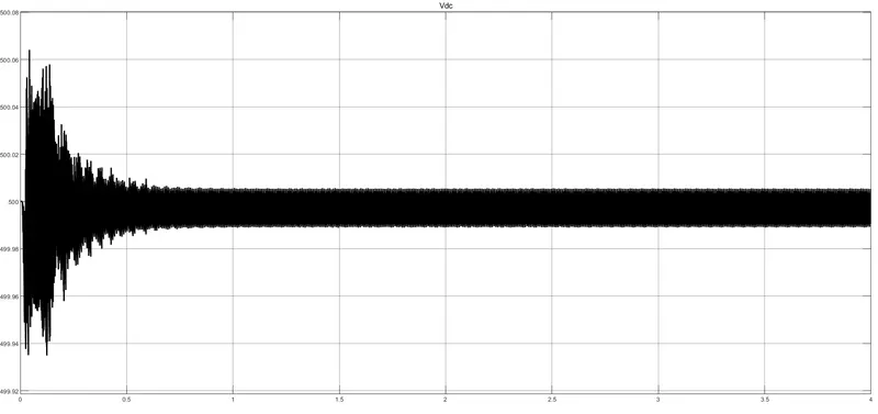
After braking resistor we get a dc voltage as 500 V.
2) abc with and without fliter
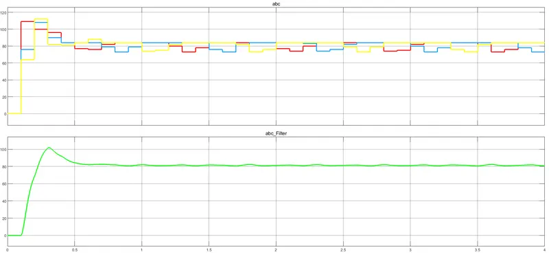
from the above plot it is clear that,by using filter,ripples can be removed.
3) Sector and Vector plot
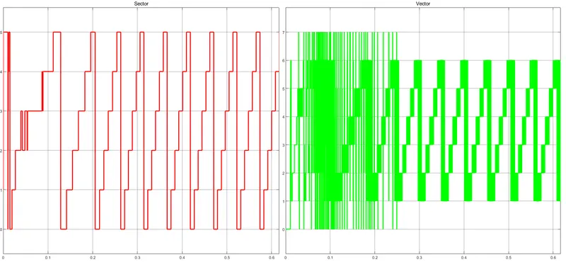
this sector and vector waveforms can be obtained in direct torque control block.
4) scope of speed,torque,flux,current.
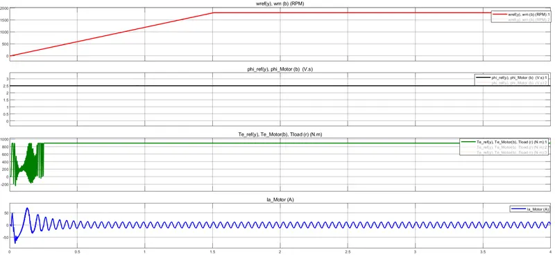
first plot is wref and wm and both waveforms are nearly match each other.this starts from zero and for 1.5 second they reach 1800 RPM and after that it is constant.
second plot is flux of motor and reference.from this second plot it is clear that 2.5 weber flux target achieved.
third plot is reference electromagnetic torque,motor torque and load torque.from this plot it can be concluded that after some oscillation at starting the torque is 890 Nm maintained constant.
forth plot is motor current and at starting current is increases up to +71 A and -75 A .after that it is in between +13 to -13 A.
From this plot,we can observe that,the flux and torque and the speed of the induction motor is controlled.
conclusion=
We can control the flux, speed and torque of an 3 phase induction motor by using DTC.
Final Conclusion=
The three phase induction motor drive is modeled and controlled using both the V/F control method and the Direct Torque control Method and also we derived the transfer function of the induction motor based on the equivalent circuit.