Project - Speed Control of a Direct Current (DC) motor
AIM
part a) To design a model for the dc motor
part b) by using PID controller to design ,develop and test a controller to maintain a desired speed for the motor.
theory =
The various speed control methods of DC Motor are
- Armature control methods
- Field control methods
- Applied voltage control methods
mathematical Modelling of direct current D.C.Motor=
Using KVL,
vs=Ra*ia+ La*dia/dt+vb; ----1
Back EMF, angular velocity and torque are related by
Vb=km*dtheta/dt, t=kt*I,vb=(km*theta)wm;
km, kt are back emf and torque constant respectively
angular velocity w=theta_dot
the open loop transfer function for the motor with the speed(w) and supply voltage (vs) can be derived as
w(s)/vs(s)= kt/(J*La*s^2) +(J*Ra+B*La) s+(B*Ra+kt*km)
from equation 1
vs-vb =ia*(Ra+s*La);
ia=(vs-vb/(Ra+s*La);
blocks used=
- Step signal-the step block provides a step between two definable levels at a specified time.
- Workspace-the to workspace block logs the data connected to its input port to a workspace from a Simulink model. typically, logged data is returned in the base workspace.
- Clock-the clock block outputs the current simulation time at each simulation step. This block is useful for other blocks that need the simulation time.
- PID controller-PID tuner provides a fast and widely applicable single loop PID tuning method for the Simulink PID controller blocks.with this PID controller parameters to achieve a robust design with the desired response time.
- Sum-the sum block performs addition on its inputs.
- Gain-the gain block multiplies the input by a constant value.
- Constant-the constant block generates a real or complex constant value signal. use this block to provide a constant signal input.
- Scope-the scope block displays its input with respect to simulation time, the scope allows you to adjust the amount of time and the range of output values displayed.
part a) design of DC motor without using PID controller.
we modulate above armature current formula ia=vs-vb/(Ra+s*La)
in this mode vb is substracted from supply voltage vs and then multiply by transfer function 1/(Ra+s*La) to get armature current ,for this armature current multiply by torque constant to get torque.
when torque multiply by rotor inertia and friction to get actual speed .
back emf constant multiply with actual speed then we get back emf which is substacted from vs .so complete closed loop process.
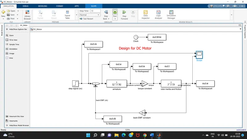
Editor window plot commands for design of speed control of DC motor without using PID controller.
close all;
subplot(321);plot(out.time,out.vs);grid;title('supply voltage (V)');
subplot(322);plot(out.time,out.vb);grid;title('Back EMF (V)');
subplot(323);plot(out.time,out.ia);grid;title('Armature Current(A)');
subplot(324);plot(out.time,out.t);grid;title('Motor Torque(N-m)');
subplot(325);plot(out.time,out.w);grid;title('Speed(rad/s)');
subplot(326);plot(out.time,out.e);grid;title('error voltage(V)');
scope response for dc motor without pid block controller.

plot response for dc motor without pid block controller.
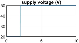
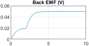
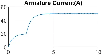
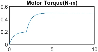
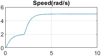
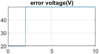
from this scope and plot result of dc motor without pid block controller .we can not control speed
only to show motor behavior or parameters .in this settling time more than 2 second .
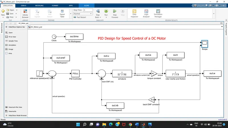
part b) model of speed control of dc motor by using PID controller
we modulate above armature current formula ia=vs-vb/(Ra+s*La)
in this mode vb is substracted from control voltage u and then multiply by transfer function 1/(Ra+s*La) to get armature current ,for this armature current multiply by torque constant to get torque.
when torque multiply by rotor inertia and friction to get actual speed
actual speed is fed back and substracted from referance speed to get error then error goes to PID controller to get control output voltage u.
so this is the closed cycle continue to get desired result.
Theory of PID controller =
PID controller describes the mathematic calculations that are applied to calculate the error between the current result and the desired set point
proportional gain=
in proportional mode, controller simply multiplies the error by the proportional gain (Kp) to get the controller output.
small proportional gain (Kp) is the safest way to get to setpoint, but your controller performance will be slow.
if the Kp is increased, overshoot in the signal will be present.
proportional action is useful for improving the response of a stable system but cannot control an unstable system by itself.
additionally, the gain is the same for all frequencies leaving the system with a non-zero steady state error.
limitations of proportional gain-
if Kp is small, error can be large
if Kp is large, the system may oscillate (that is become unstable).
Integral gain=
the role of integral control is to eliminate the droop.
it is also called reset control as the set point is continuously reset as long as an error is present.
thus, it automatically pushes the process value towards the desired set point once droop occurs.
Even when the setpoint is changed, the integral control will work to eliminate droop.
Derivative gain=
the role of derivative control is to reduce or eliminate overshoot and undershoot.
derivative control, also called "rate”, measures the rate of parameter change in the process value.
control law design and test
Editor window plot commands for design of PID controller based speed control of DC motor.
Process for tuning
for this PID Tuning we use following process
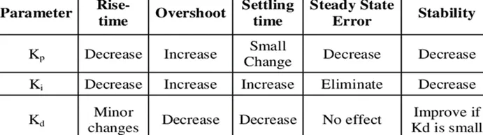
1) set Kp, Ki and Kd to 0
2) increase Kp until gets close to setpoint
3) stop if behaviour is good enough
4) increase Ki until reaches setpoint quickly
5) increase Kd until oscillation is reduced
Actual PID controller block
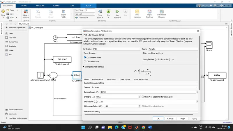
so after the PID controller we need to start with the kp,ki,kd such as 1.0,1.0,0 . we follow above table or above process for tuning so by this we can adjust the kp,ki,kd values as 31.59,82.37,2.35.
this values are used to maintain the control design objectives
Scope response of modelling of speed control of dc motor with PID controller.
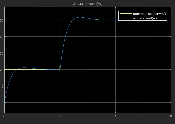
Plot response of modelling of speed control of dc motor with PID controller.
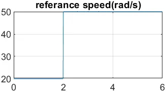
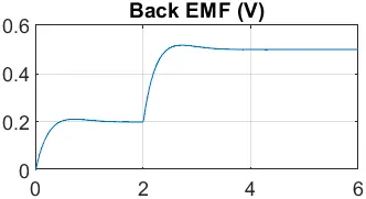
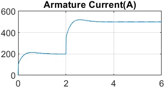
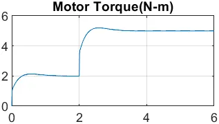
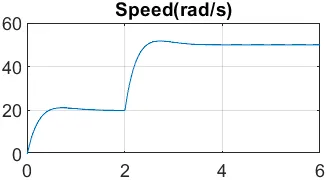
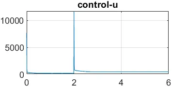
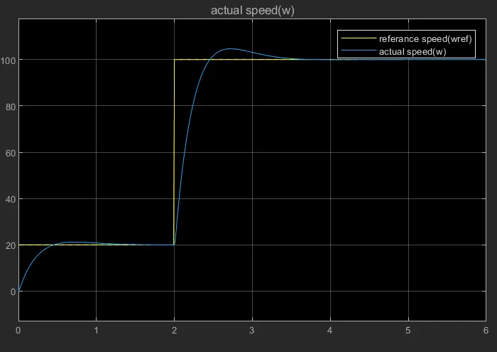
above response obeys following control design objectives
settling time less than 2 sec
overshoot less than 5%
steady state error less than 1%
these are showing best tracking and good response behaviour
Stability of a dynamic system
the first scope response showing when referance final value is 100 ,initial value is 20 and step time is 2 sec
the second scope response showing when referance final value is 200 ,initial value is 20 and step time is 2 sec
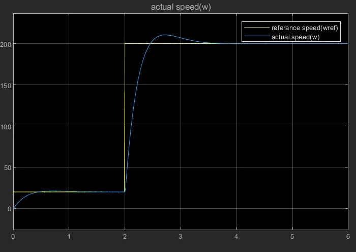
from above 2 response we can concluded that both the plots response behaviour is same ,so by this we can say that we tracking best desired speed of dc motor.
Conclusion=
In this dc motor speed control model, PID control provides more control action sooner , this reduces the effect of a disturbance and shortens the time it takes for the level to return to its set point.
A proportional, integral, derivative controller design is demonstrated to obtain the desired angular speed using the appropriate supply voltage.
we found that using PID, we can make a system stable, good and quick response.
Now, in this way ,we have designed a closed loop system with least overshoot, no undershoot, fast rise time and no steady state error.