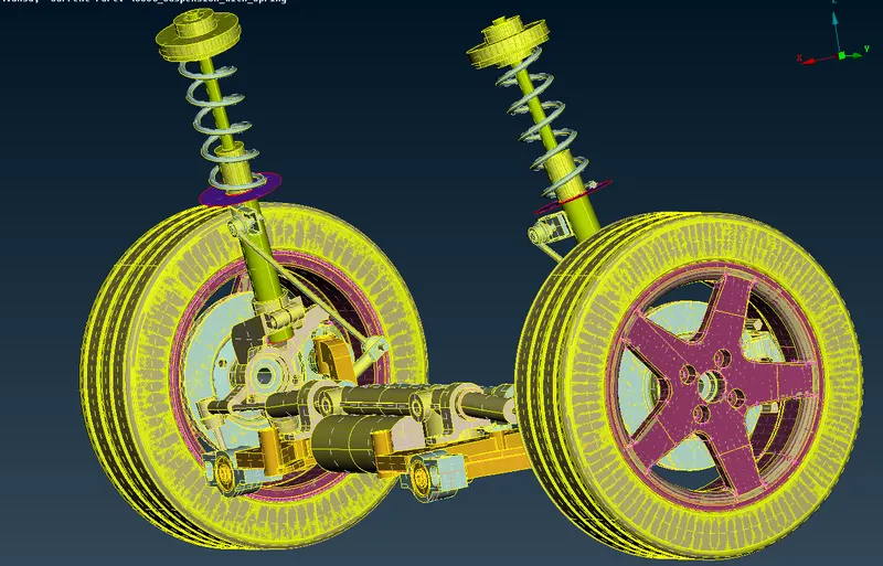
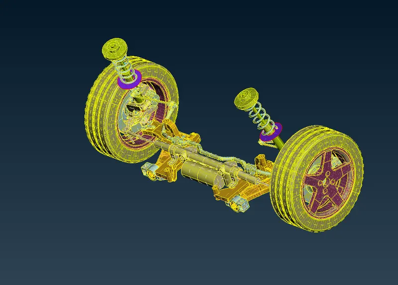
Project - 2 - Meshing on the suspension Assembly
Project - 2 - Meshing on the suspension Assembly
AIM
To check for the geometrical errors and mesh with the given element Quality criteria. After meshing the component the thickness has to be assigned for mid surfaces. Use tetra elements to model non-uniform thickness components.
PROCEDURE
- To insert the component in the working place
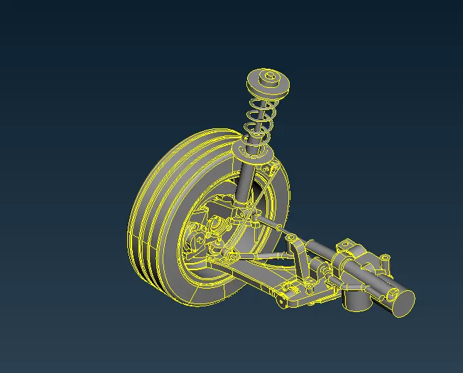
- now we start from tyre and rim
- so we have to isolate the other component by using inot
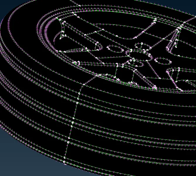
- now we isolate the component and we have to give the volume mesh for the region with the following quality criteria
-
S.No
Quality Criteria
Value
1
Target/Average length
6.5
2
Minimum Length
5
3
Maximum Length
10
4
Skewness
45
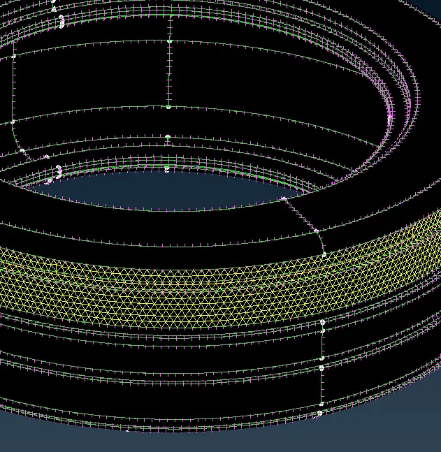
- and then we giving the mesh to the tyre one by one
- after completing the mesh for the tyre
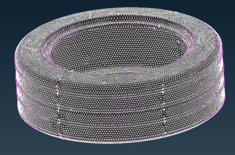
- In the same way, we have to mesh the part with the same quality criteria
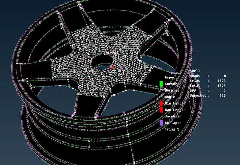
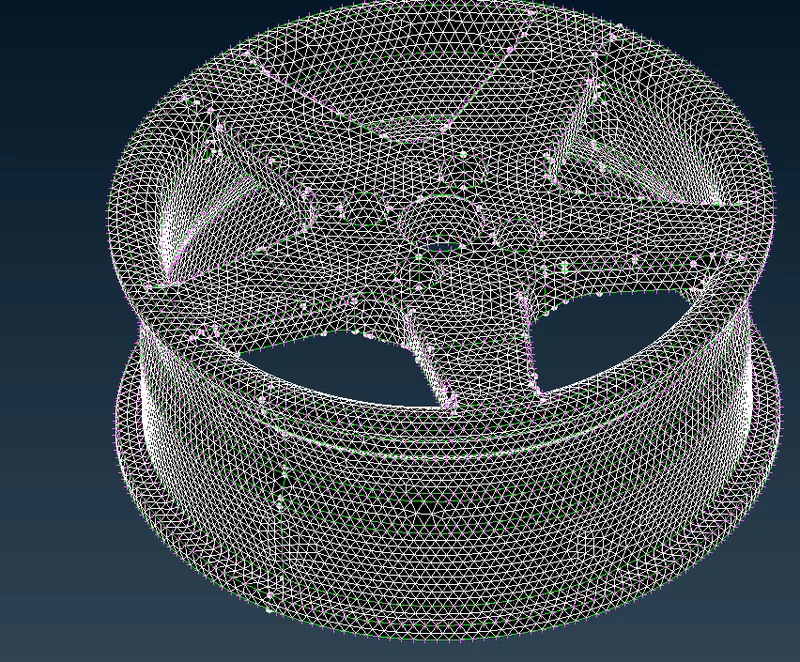
- now we have to give the volume mesh
- go to volume - define - auto/manual-define the part
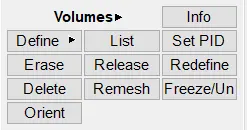
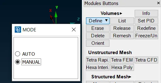
- after define the part it shows that volume meshed 1
- that means it already defined but didn't give the mesh
- so go-to list - and remesh the component
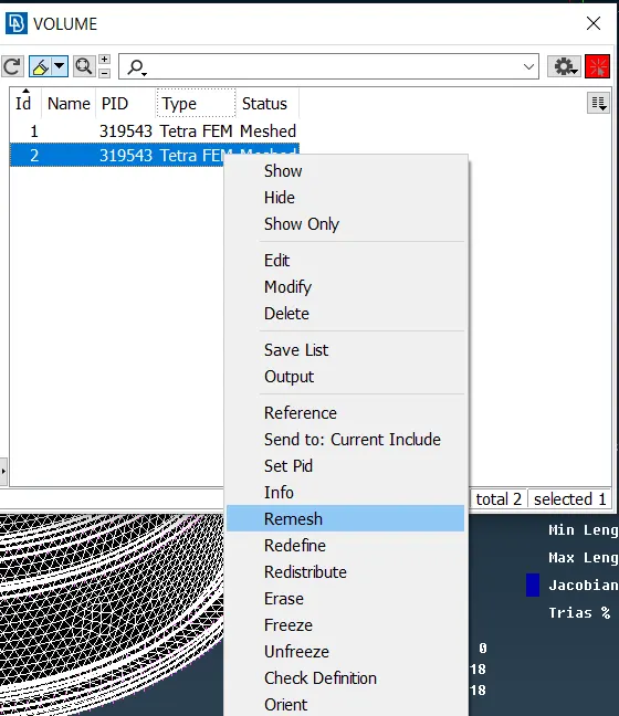
- now we completely volume ,mesh the tyre and rim
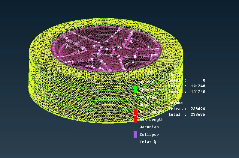
- now we have to mesh the other components but this time we have different quality criteria
- other than tyre and rim we have to follow these quality criteria
-
S.No
Quality Criteria
Value
1
Target/Average length
4
2
Minimum Length
2
3
Maximum Length
6
4
Skewness
45
- now we have to isolate the parts other than tyre and rim using inot
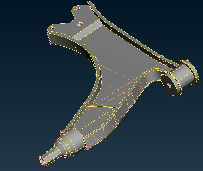
- following the same thing to the component mesh one by one
- after meshing the whole component we have output like this
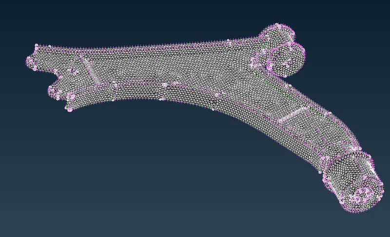
- this is the method and this is the quality criteria for upcoming parts
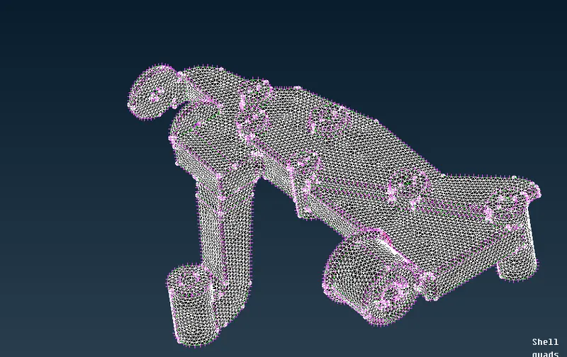
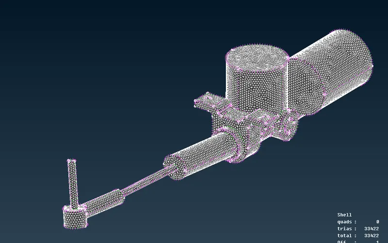
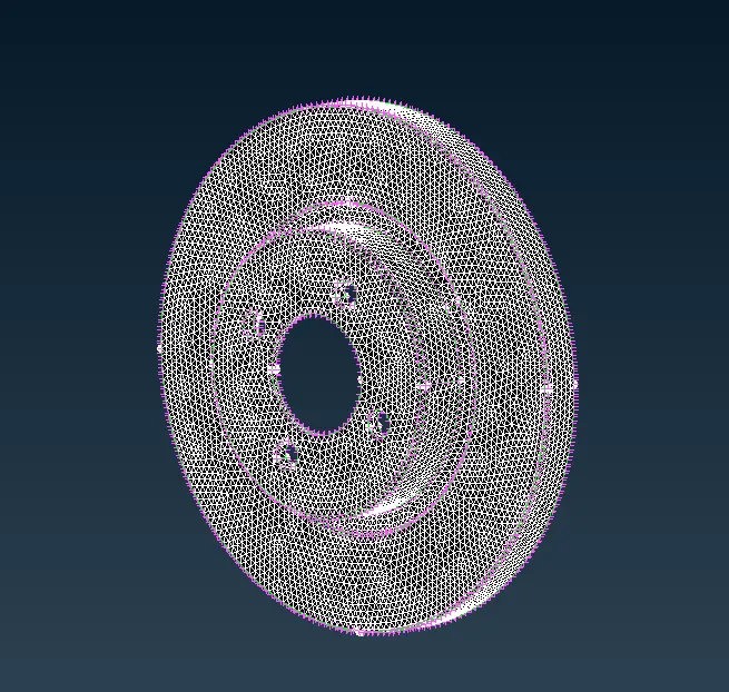
- after meshing all parts
- follow the same procedure to give volume mesh
- volume - define -list - remesh
- now we have to give the represent to the spring with the 1D element
- isolate the spring alone
- and select the middle option and create the curve
- after that connect the all the curve into single long curve
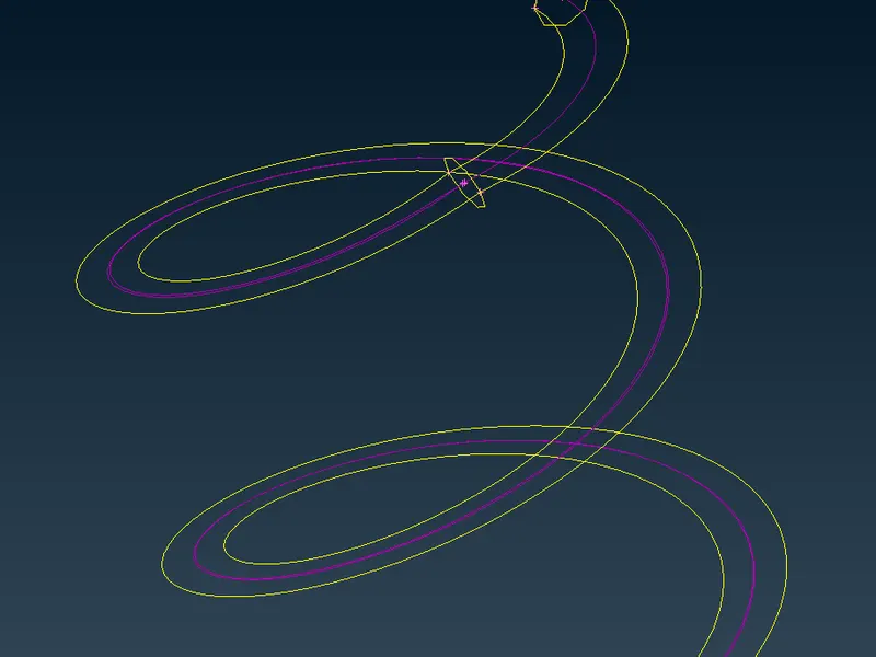
- after that create on COG point
- and go to nastran and select the CBAR
- and change to curve box
- and select the COG point
- and also give the radius as 5
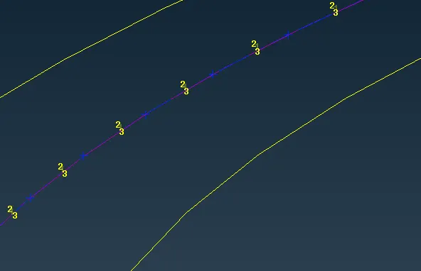
- go to quality criteria - presentation parameters - click on the line elements and select the solid option
- we have a cbar like this
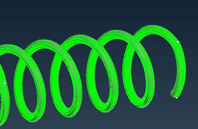
- after that we have symmetry the component because its symmetry component
- go to transform - copy - symmetry - 3 points
- select the 3 points
- and apply we have a result like this
-
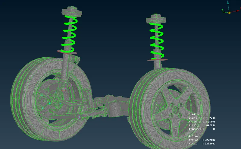
RESULT
we check for the geometrical errors and mesh with the given element Quality criteria. After meshing the component the thickness has to be assigned for mid surfaces. and we Use tetra elements to model non-uniform thickness components. Also, use Appropriate connections to connect the components