Project - 2 - Meshing on the suspension Assembly
Project-2
Aim: For the given assembly, check for the geometrical errors and mesh with the given element Quality criteria.
Common Note:
- Use Volume mesh for Tyre and Rim with below Quality criteria. (Use Tria Element)
- Use mid surface only when the thickness is uniform and less than 5 mm. (Use Mixed elements)
Quality Criteria for Surface Meshing of Tyre and Rim (Element type: Tria):
|
S.No |
Quality Criteria |
Value |
|
1 |
Target/Average length |
6.5 |
|
2 |
Minimum Length |
5 |
|
3 |
Maximum Length |
10 |
|
4 |
Skewness |
45 |
Quality criteria for Surface Meshing of Non-Uniform thickness components other than Tyre and Rim (Element type: Tria):
|
S.No |
Quality Criteria |
Value |
|
1 |
Target/Average length |
4 |
|
2 |
Minimum Length |
2 |
|
3 |
Maximum Length |
6 |
|
4 |
Skewness |
45 |
Quality Criteria for Volume meshing of all Non-Uniform thickness components (Element type: Tetra Elements):
|
S.No |
Quality Criteria |
Value |
|
1 |
Tet-collapse |
0.2 |
Quality criteria for Mid surfacing of Uniform thickness part which has thickness less than 5 mm (Element type: Mixed elements):
|
S.No |
Quality Criteria |
Value |
|
1 |
Target/Average length |
4 |
|
2 |
Minimum Length |
2 |
|
3 |
Maximum Length |
6 |
|
4 |
Aspect |
3 |
|
5 |
Warpage |
15 |
|
6 |
Skewness |
45 |
|
7 |
Jacobian |
0.7 |
|
8 |
Minimum Quad Angle |
45 |
|
9 |
Maximum Quad Angle |
135 |
|
10 |
Minimum Tria Angle |
30 |
|
11 |
Maximum Tria Angle |
120 |
OBJECTIVE:
- Importing the rear suspension geometry in ANSA
- Geometrical clean-up
- Generate volume mesh for solid parts
- Improve the mesh flow and solving off element according to given quality criteria
- Create a connection of Rear suspension for NVH analysis
Introduction:
Suspension has been essential component of Automobile, the rear suspension of vehicles performs the same general function as front suspension, but the construction of rear suspension is quite different. The ideal suspension for vehicle depends a lot on the vehicle’s body style and performance requirements. The most basic purposes of suspension system is to prevent the body of vehicle from hitting the ground and shock and also to keep the tires in contact with road.
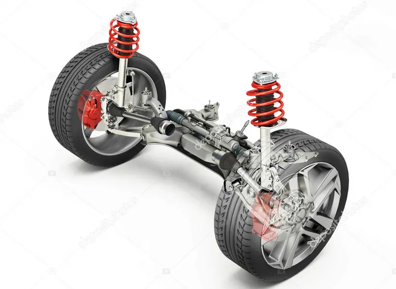
Source: Depo-site photos
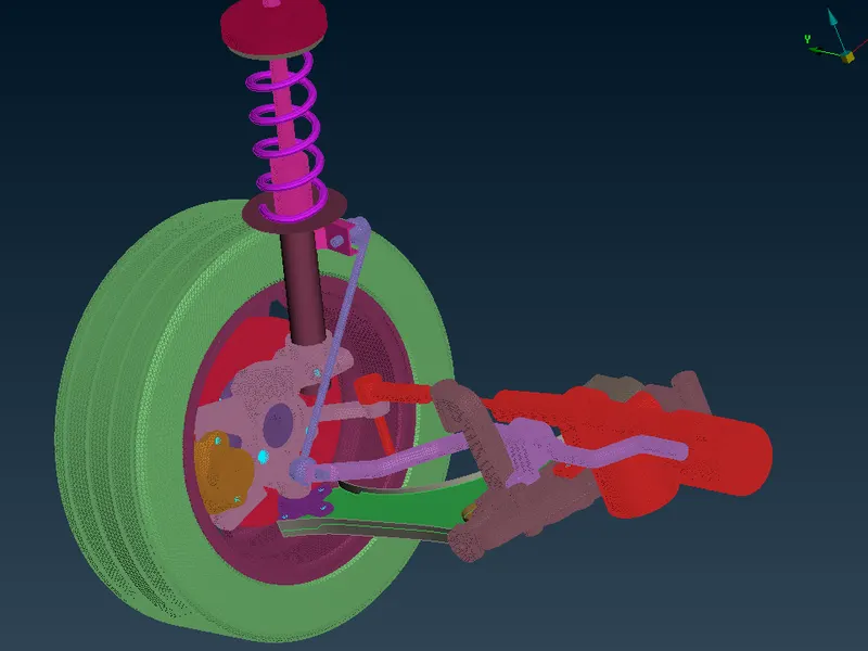
Rear suspension model
Suspension system are generally classified into dependent and independent system. The wheel in dependent system are perpendicular to the axle and parallel to each other, the most common type of this suspension is leaf spring rear suspension.
Procedure:
- Import the geometry into ANSA and doing topo to stich the surfaces, isolate the parts to got the proper view of the each and every part of the rear suspension assembly
- Then we have to clean the geometry, check the errors by using check manager in ANSA
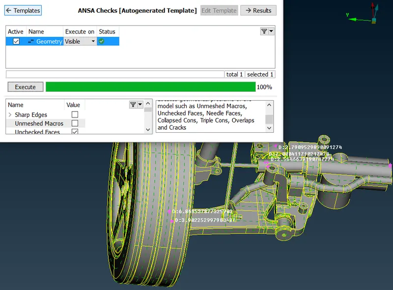
Cleaning the geometry
- Surface Mesh generation for tyre and rim
For tyre and rim we have to mesh it with tria elements then we have to convert that tria into tetra element, we have to mesh it with given quality criteria as mentioned above.
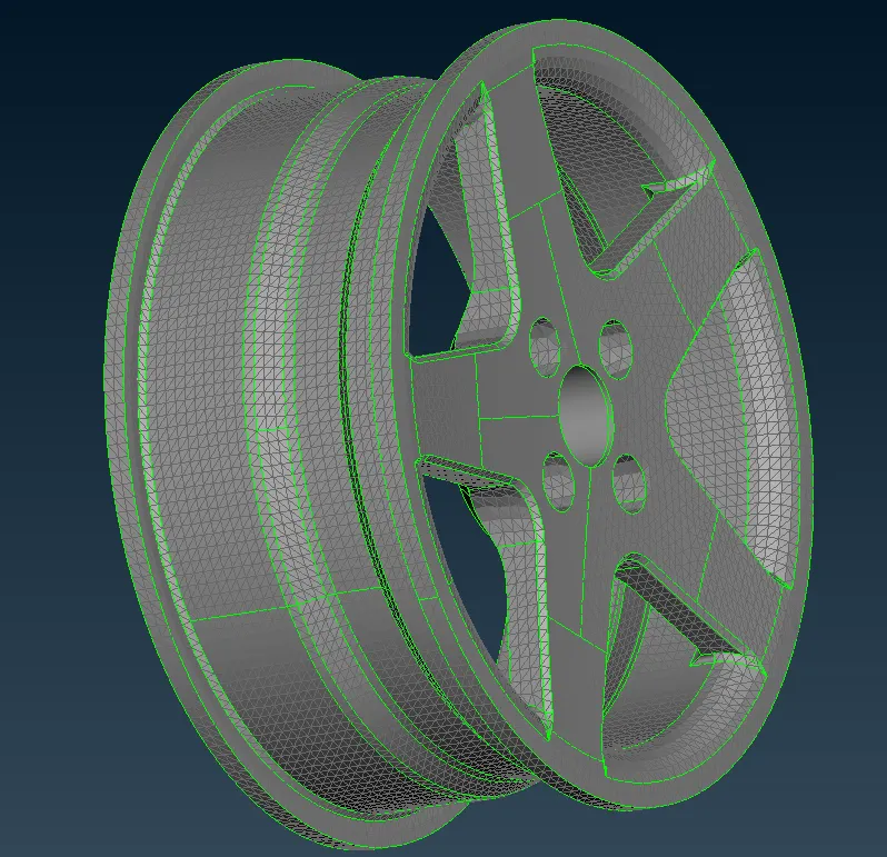
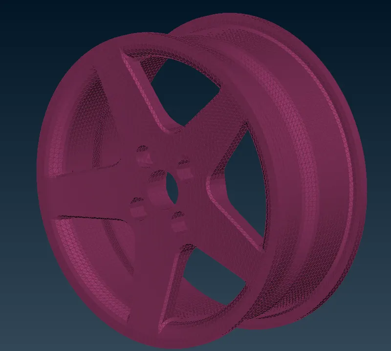
Mesh generation of rim
- Mesh generation of tyres
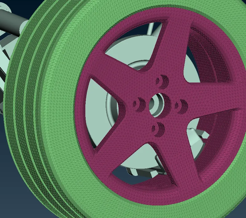
- Surface mesh generation other parts of the assembly
For rest of the component, we have to mesh according to the quality criteria as mentioned above
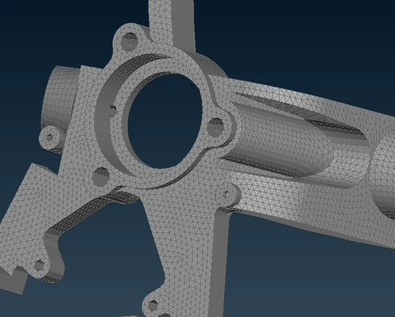
Surface mesh for steering knuckle
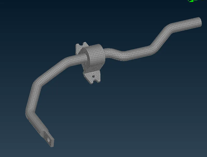
Surface mesh for control bar
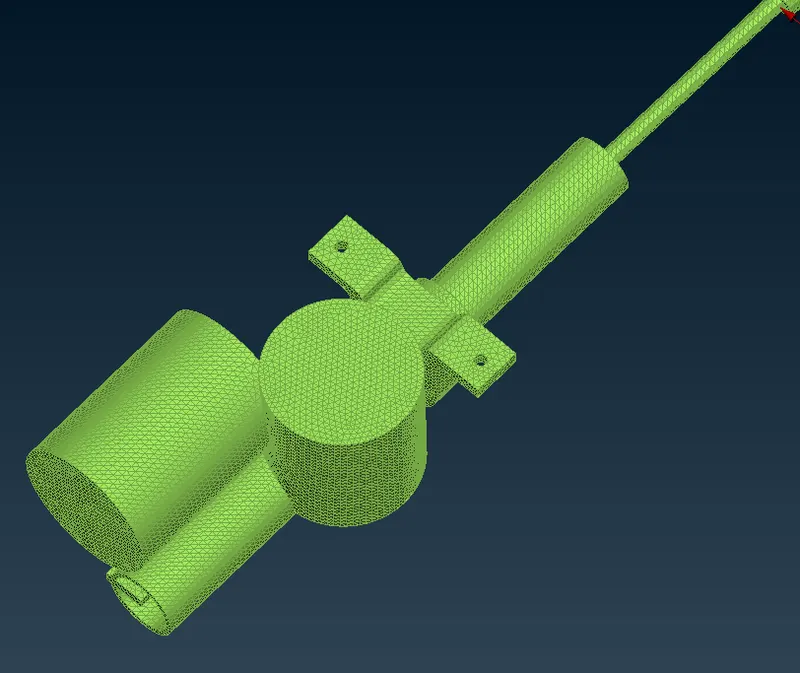
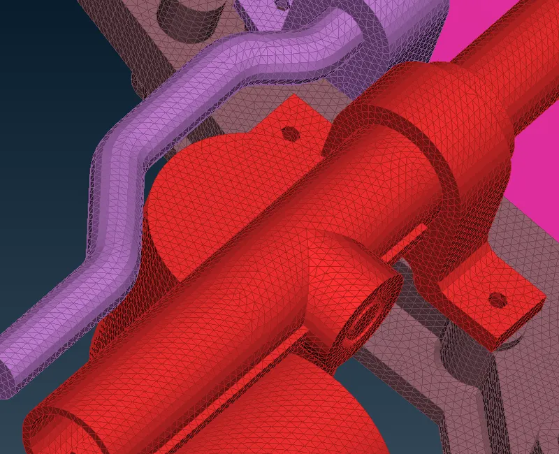
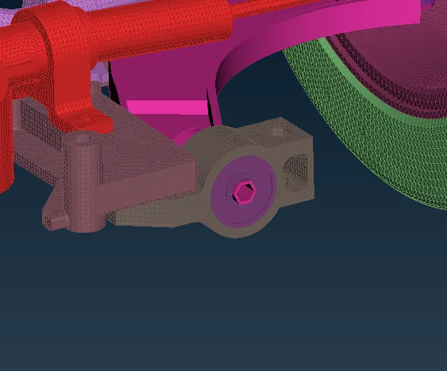
Surface meshing of rest of the part of the rear suspension assembly
- Now we also have component whose thickness is less than 5 mm, for that component we go to 2d meshing method by extracting the mid-surface of the component and then mesh the component with quality criteria as mentioned above and then assigning a proper thickness to it.
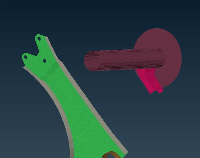
Shell meshing of Wishbones and Macpherson strut
- Now for volume meshing we have to convert that tria elements into tetra elements
When to use 3D elements
We use 3D elements when all of the dimension are comparable ( x-y-z)
Element shape: Tetra, Penta, hex, pyramid
Additional data from the user: nothing
Element type: Solid
DOF for solid elements:
Solid elements only have 3 translation DOF (Degree of freedom), no rotational DOF
Tetra-Meshing Technique:
There are two method of tetra meshing
- Automatic Mesh: This approach is limited to simple geometries and pre-requisite is for error free CAD model. User has to just select the volume and software automatically carried out meshing as per specified element length, quality criteria.
Advantages: Very quick, no meshing effort
Disadvantages: Result in very high number of nodes and elements, There, is no control on mesh flow lines and specific meh pattern requirement (like bolted, welded joint or contact surface simulation)
- 2D tia to 3D tetra Most commonly used method. Quad or tria meshing is carried out on all the outer surface of the geometry, quads split into trias and then converted into tetras
- Here we are using 2D tria to 3D tetra option for generating volume mesh
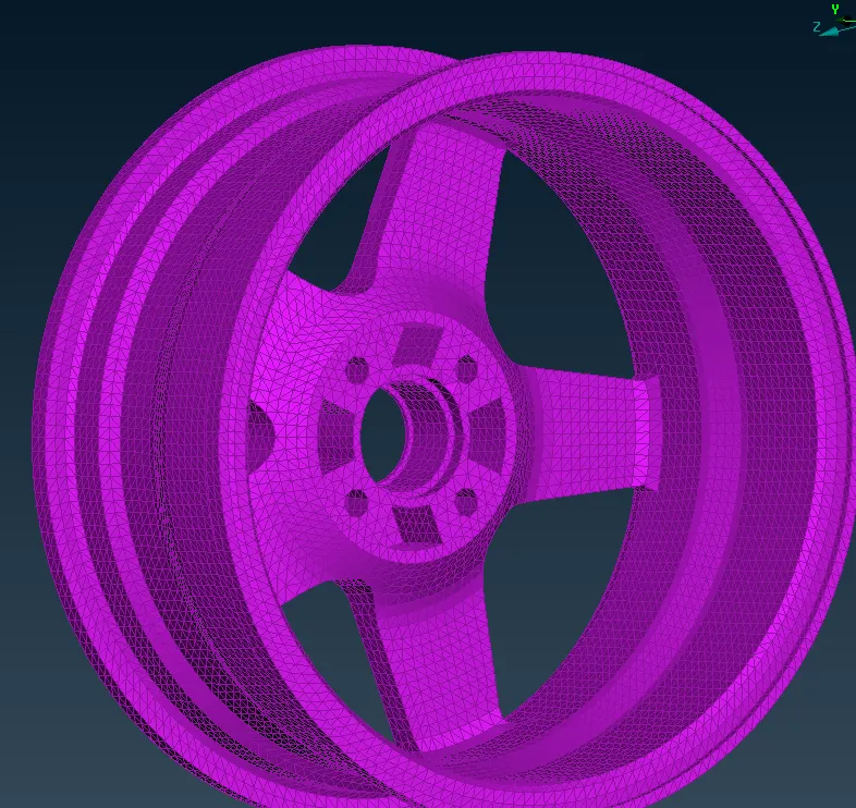
Tetra meshed model of Rim
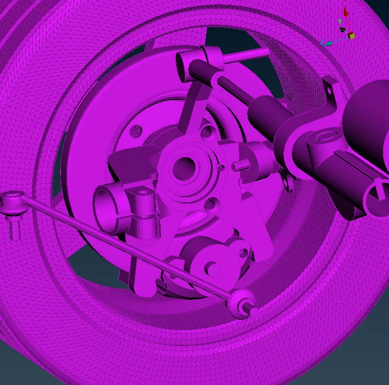
Tetra meshing of rear suspension of the vehicle
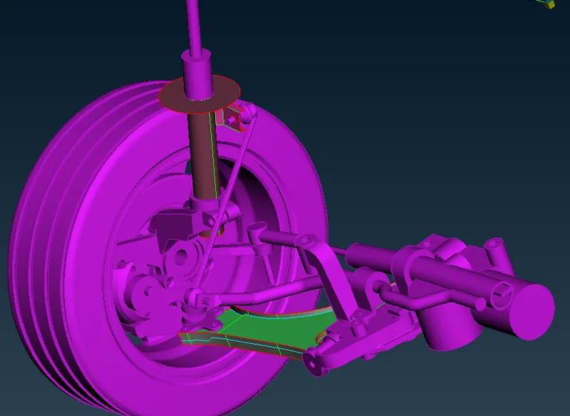
Volume and shell meshing of Rear suspension Assembly of the vehicle
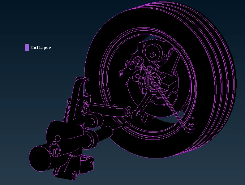
Checking for Tet collapse value
- Now we have left only the suspension spring, to modelled the spring we have 2 different ways, one is to model it as 1D element and other it to represent by volume meshing. For Hexa-meshing we are using extrude option and glide option in Volume mesh panel
Here we are using Hexa meshing to model the spring
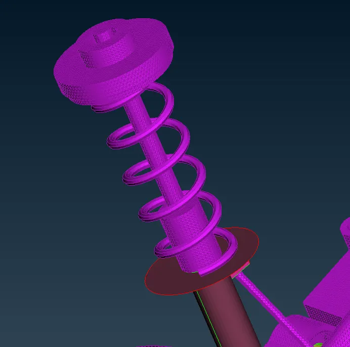
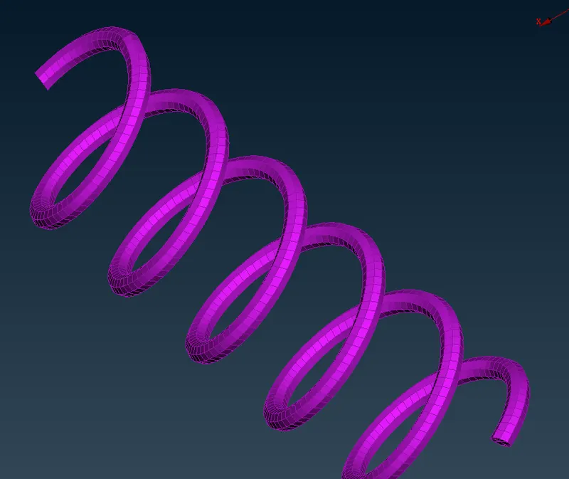
Hexa-meshing of the spring
- Final step is to connect the different parts of the assembly (NVH domain). For NVH analysis we are not take care about mechanism, we are joined it by rigid elements to rigidize the connection between parts.
Introduction to connection
- 1D Elements: 1D elements are simple connection between the nodes
- Standard 1D elements are
- RBE2(Rigid link to distribute load having infinite stiffness)
- RBE3(Rigid link to distribute loads)
- Beam/Bar (Non rigid link that has a property that include a cross-section and material definition)
Connectors:
- Connectors are the geometric entity that define the connection between other entities, in simple word we can say that connectors are used to connect the un- connected parts of the model, so that load can be transfer from one part to other parts.
- Used for welding, bolts, adhesives etc
- Link geometry of FE entity
- Can be realized into FE representation of welds, bolts etc.
- Connectors allow for easy and rapid creation of FE welds, bolts, adhesive etc.
Types of Connectors:
- Spot: Connection at a point, spot weld rivet etc
- Bolt: Connection at hole location
- Trim Mass: Non-physical mass, simplification through the replacement of parts with mass only or add mass to existing part
- Seam: connection along length, seam welds, connect geometry only
- Area: Connection of areas, example Adhesive etc.
Connectors: Terminology
- Link Entities:
- The entities that are being connected
- User can explicitly define links entities or specify a search tolerance
- Can be components, elements, surfaces, nodes, or tags
- Typically, components are linked
Connector location:
- Where the entities are linked
- Nodes: created at the node location
- Points: created at the point location
- Lines: created for the lines
- Elements: created at the element location (adhesive only)
- Surface: created at the surface location (adhesive only)
Connector State:
- Whether an FE representation of connector has been created
- Unrealized: The initial status of the connector entity upon creation, it means connector is created but not realized.
- Realized: The status only if creation of FE weld representation at the connector was successful.
- Failed: The status only if the creation of FE representation at the connector was not successful.
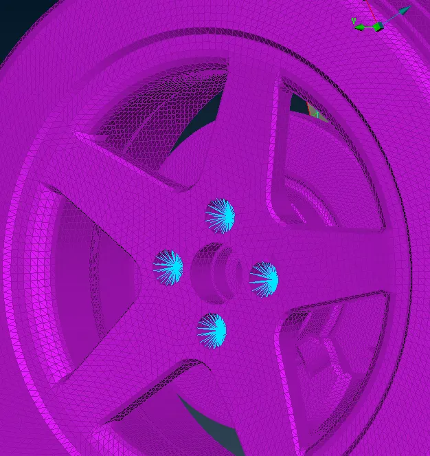
Bolt connection
BOLT connection
Connection establishment of two hole by using BOLT connection
- Now for Bolt connection, we basically use two methods to create bolt connection, one is manual method and other is automatic creation of bolt by the help of connection manager.
Converting a 3D point into Bolt
- To create Bolt by using connection manger, firstly we have to create the 3D point at the centre of the hole by using On COG option in geometry panel, after creating the 3D point, next step is to convert that 3D point into bolt by using convert option in Assembly section, after converting it to Bolt, we can see the symbol of the bolt, Now to realize the connection we have to go to connection manger option in Assembly section, here we have to define the number of parts to be joined as P1, P2, P3… , also we have to define the Bolt connection as rigid, and then we have to specify the search tolerance and then click on Apply and then click on Realize to realize the connection
- We can also create Bolt by using cluster RBE2, selecting one hole at a time and join it by cluster RBE2 and to define the bot body or stem we can use 2-Node RBE2 to make connection among the parts
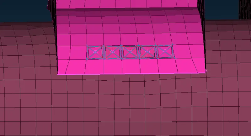
Spot weld connection
- Now we create the Spot weld connection to join the parts, to create spot weld firstly we have to define a 3D point between elements by using ON COG option in geometry Panel, select the Edges and then creating the 3D point between the selected edges, after that we have to convert it into Spot weld by using convert option in Assembly section. After converting 3D point into spot weld, then we have to realize the connection by using connection manager.
- We can also connect these two parts by Seam weld
SEAM weld connection
Seam weld connection can be represented in two ways
- By Rigid elements
- By Shell elements
Note: Representation of weld connection will vary domain to domain, here we are creating seam weld connection on the basis of NVH domain
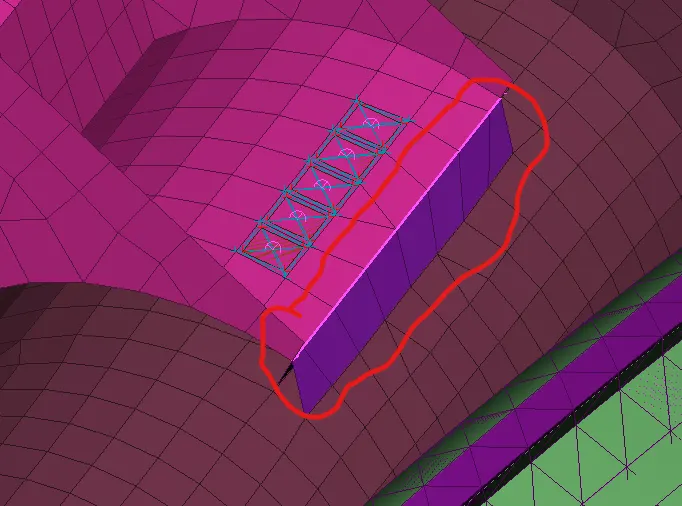
Seam weld connection
Final Meshed model of rear suspension
- Now we have to reflect the half part to the other side by using symmetry option in ANSA
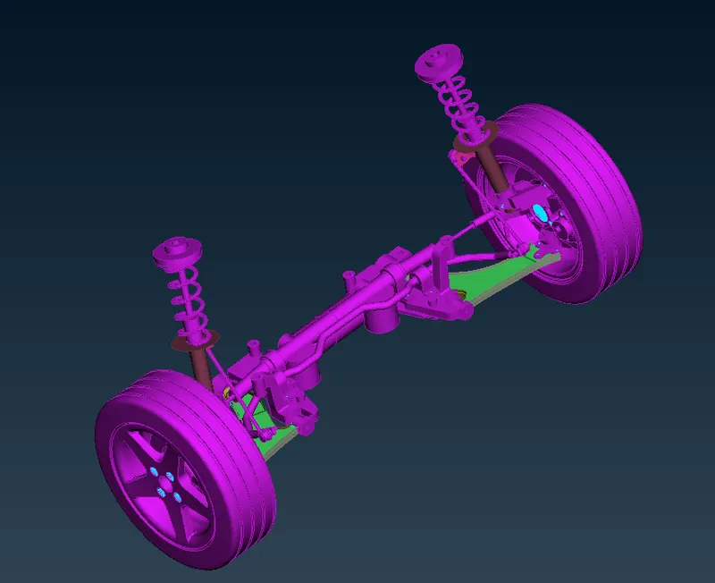
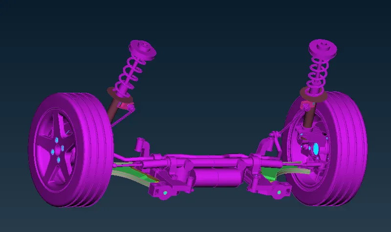
Meshed model of Rear suspension of the vehicle
Learning outcomes:
- Understanding about the combined use of solid meshing and shell meshing to model the components
- Understanding about the different method to model the spring
- Understanding the concepts regarding the connection
- Able to deploy different type of connection