Project - 2 - Meshing on the suspension Assembly
Aim:
In this project, ANSA pre-processor is used to check for geometrical errors on the given suspension system and mesh the component with the given quality criteria using tetra elements where thickness is not uniform and with mixed elements (Tria and quad) where the thickness is uniform (thickness less than 5mm) Also to deploy connections in the required area of the component.
Steps Involved:
1. Importing the CAD geometry into ANSA
2. Perform geometric checkup and then clear the errors if any present
3. Generate the midsurface for unifrom thickness components and assign different PID's according to their thickness
4. Setup Quality criteria and mesh parameters
5. Meshing the components and then improving the mesh using various tools available in ANSA.
6. Volume definition and 3D mesh generation for other than mid surfaced components.
7. Implementation of connection at required areas.
Quality parameters:
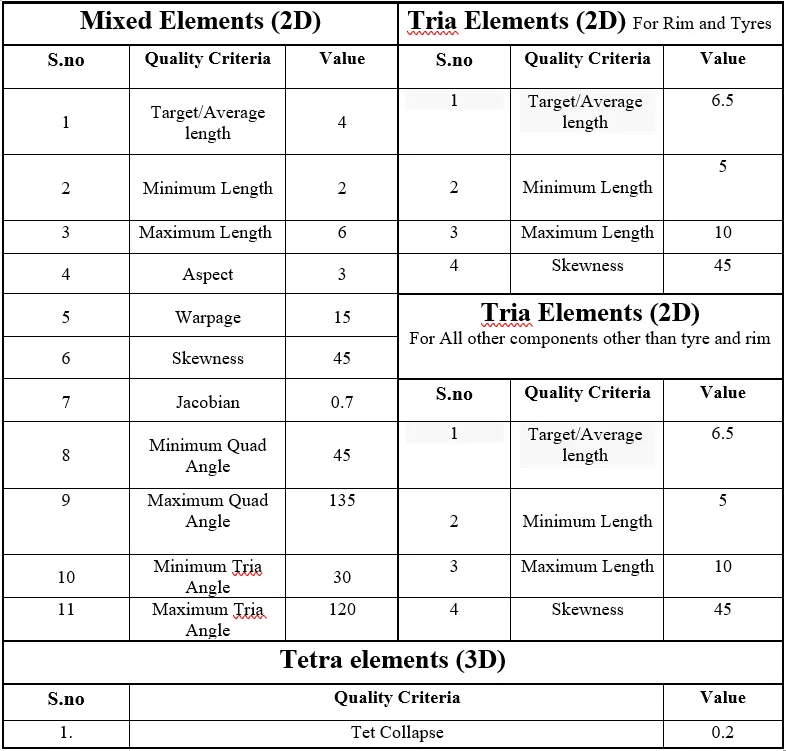
Theory:
A Suspension system is the term given to the system of springs, shock absorbers and linkages that connects a vehicle to its wheels. the purpose of suspension system is to isolate the vehicle body from road bumps and vibrations while keeping the vehicle in contact with the road.The springs support the weight of your vehicle, acting as a flexible link allowing the frame and body to ride relatively undisturbed while the tyres and suspension follow the road.
Modern suspension systems are based on four basic designs: leaf springs, coil springs, torsion bars, and air springs.
Basic suspension movements:
1. Bouncing: The vertical movement of the complete body.
2. Pitching: The rotating movement of all the parts between the spring and road and the portion of spring weight itself.
3. Rolling: The movement about longitudinal axis produced by the centrifugal force during cornering.
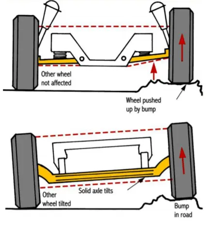
Components of Suspension System:
- Springs, which neutralize the shocks from the road surface (Energy storage)
- Dampers, which act to improve comfort by limiting the free oscillation of the springs. (Energy Dissipation)
- Stabilizer (sway bar or anti-roll bar), which prevents lateral swaying of the car.
- A linkage system, which acts to hold the above components in place and the control the longitudinal and lateral movements of the wheels.
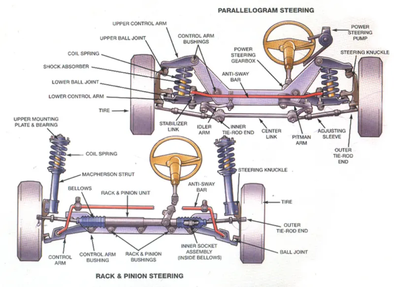
Procedure:
Geometric topology:
1.The given part is imported into ANSA
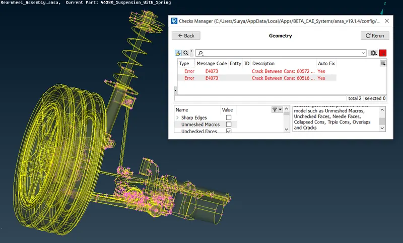
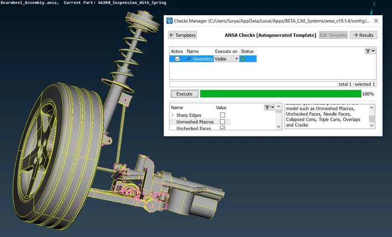
2.The component is checked for geometrical errors using the checks manager.
3.The Errors which are displayed is cleared by using the auto fix option in checks geometry and by also using the tools available in hot points, cons, faces and surface.
Geometric errors before topology:
Model without geometric errors:
Part Segregation Under different Part ID:
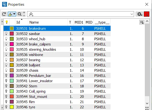
- Once all the geometric errors are cleared different parts are segregated into different PID's
Mid surface Extraction:
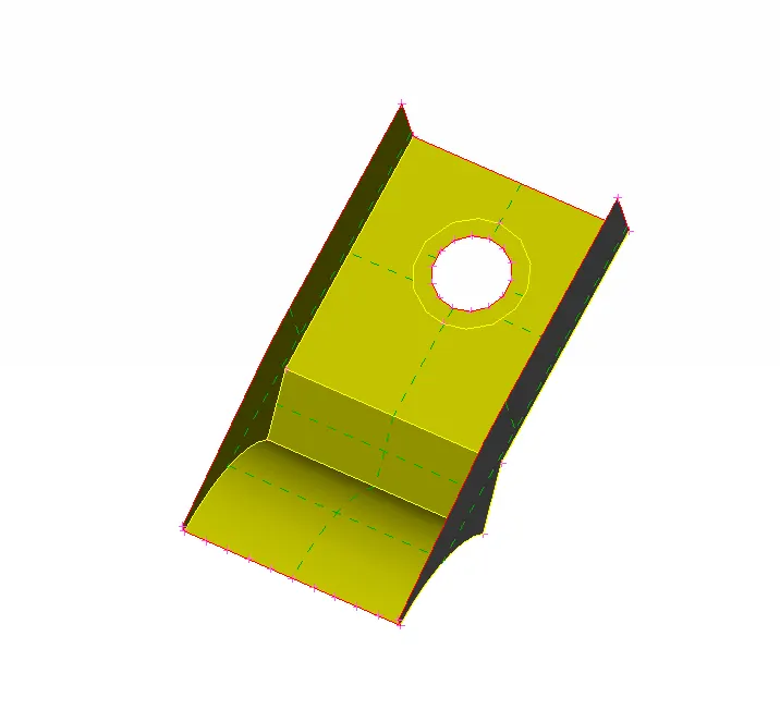
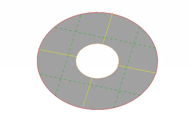
Midsurface extraction is done only if the component with uniform thickness of less than 5mm, there is only three parts present which have thickness less than 5mm
1.OFFSET method: The offset option available in FACES module is used for extracting the midsurface of the outer circular surface.
2.SINGLE-MIDDLE method: The single middle option available in FACES module is used for extracting the mid surface of ribs.
3.MULTI-MIDDLE: The multi middle option available in FACES module is used for extracting the midsurface of small ribs and supporting structures which are available in the component.
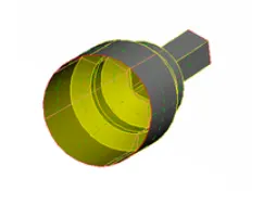
The Extracted Mid surface is as follows:
MESHING & Mesh corrcetion (2D):
1.Once again geometric check is performed using the checks manager.
2.The given quality criteria and mesh parameters values are entered.
3.Mesh is generated using the best mesh option element type is selected as trias.
4.The component is checked for quality criteria which is achieved by using various tools available in the modules like Cut, join, Num +/-, Reconstruct, Smooth etc.,
5.Smooth mesh flow is achieved.
Meshed Parts as follows:
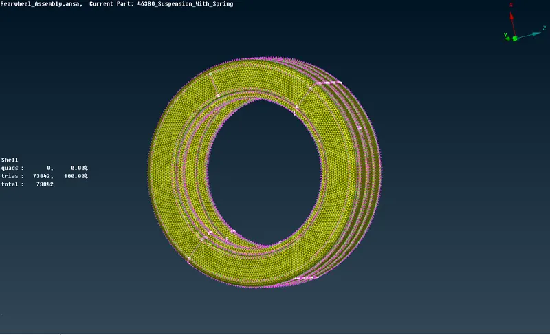
Tyre Shell meshed
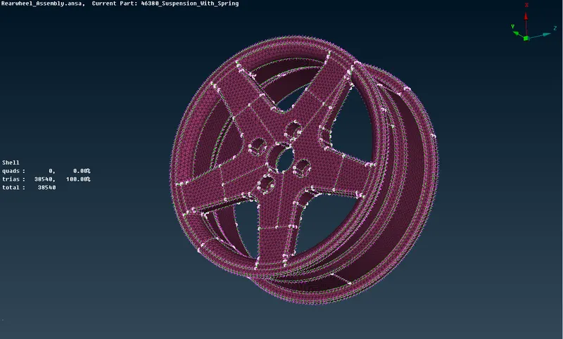
Rim Shell meshed
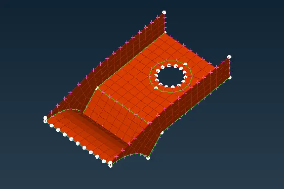
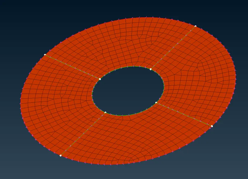
Strut mount shell meshed
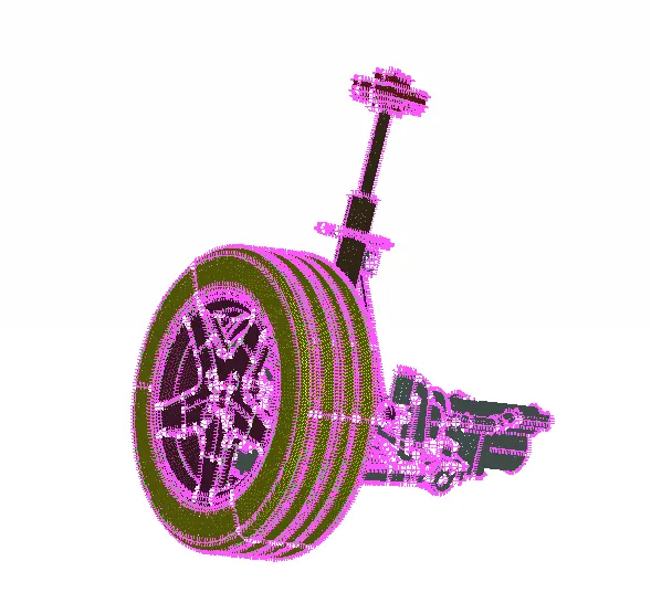
Fully Shell Meshed Suspension System
Volume definition and 3D mesh generation:
The Next step we need to do is define the shell meshed tetra element components volume, but before defining them on the list we need to make sure the part is properly meshed and closed. Also the part should not contain any overlapping surface. Define them one by one and set different PID's type solid, here i have used Rapid Tetra mesh to generate the tetra elements inside the volume.
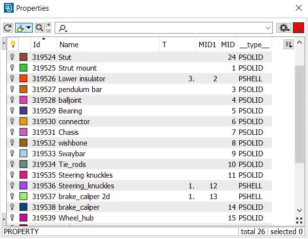
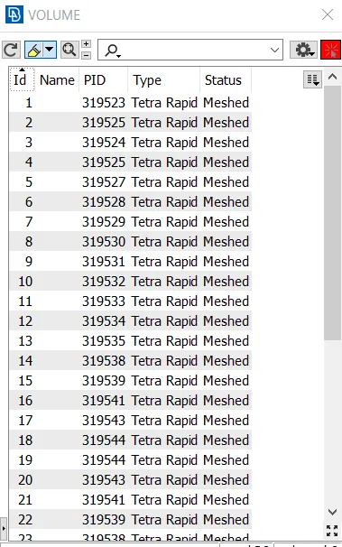
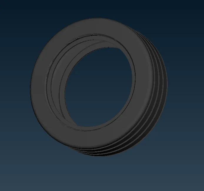
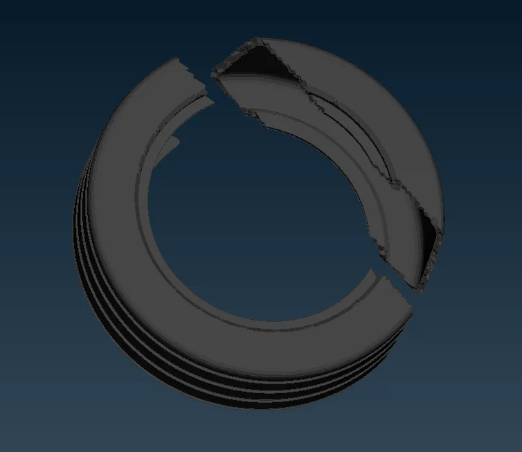
Volume meshed Tyre
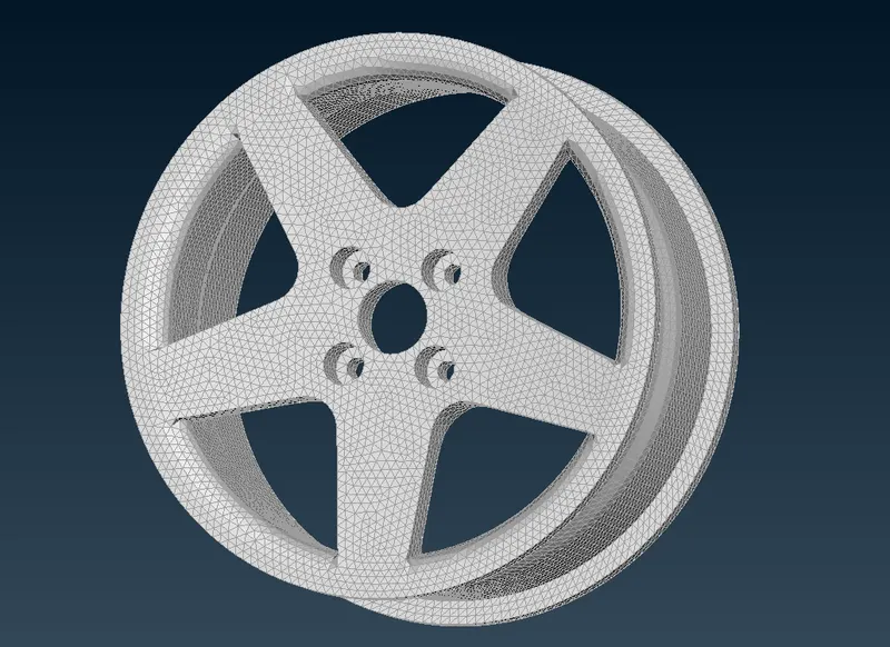
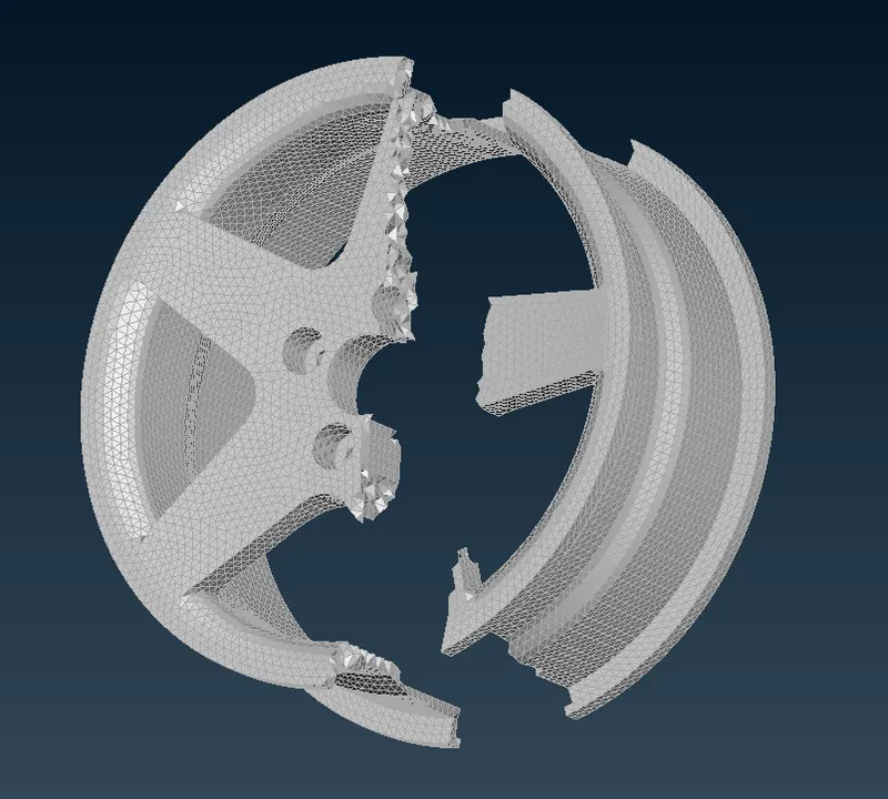
Volume meshed Rim
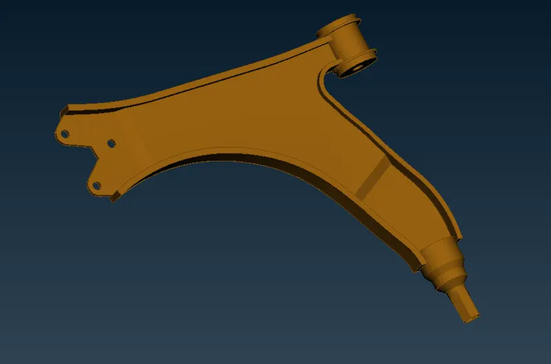
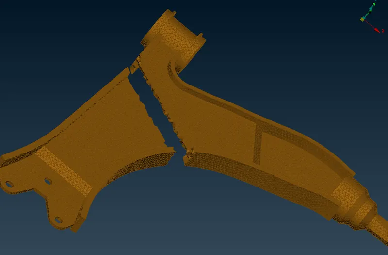
Volume meshed Wishbone
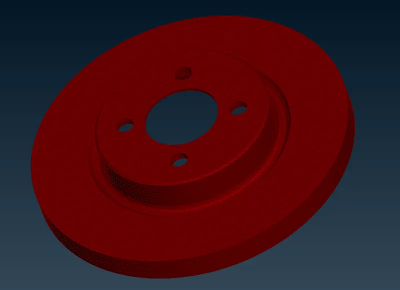
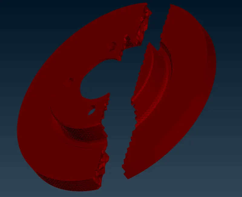
Volume meshed brake
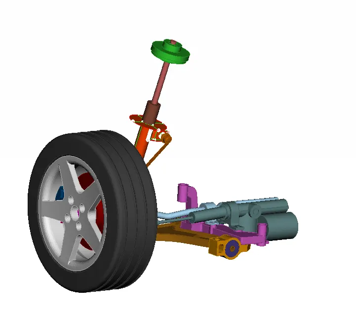
Volume meshed Component Final
Modelling Suspension spring:
- CBAR defines a simple beam elements between two selected grid points
- Convert the spring into a curve that should pass through the axis of it by the following steps Topo `rarr`Curves`rarr`Middle
- Using the connect option convert the multiple curve into a simple curve by the following commands Topo `rarr`Curves `rarr`Connect `rarr`Multi
- Now with this curve in the middle of the spring select the CBAR options from the Nastran deck
- Select curve option from it and do a box selection on the curve
- Then we need to input the average element length and update the value of diameter so that the area automatically calculated and PBAR PID is also created.
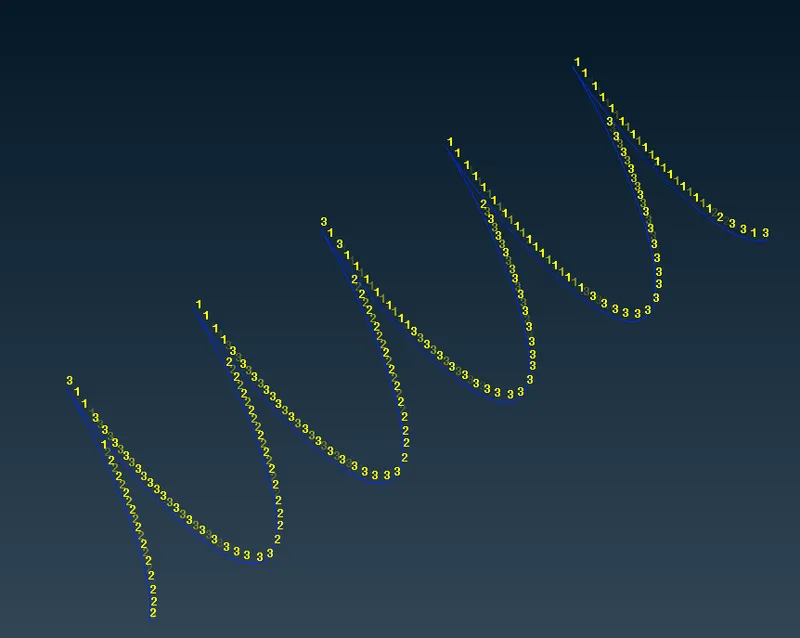
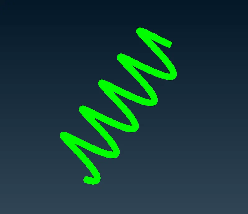
Detailed element Representation
Connectors:
Depending up on the model requirement various types of connectors are used, Such as many node RBE2, Two node RBE2, Cluster RBE2, weld and bolt connectors. In this suspension assembly, Rigid and bolt connections are used with adjacent FE macros. In all the hile regions the connection is made using bolts. Many nodes are selection for making cluster RBE2 bolt connectors. The Master nodes of two clusters RBE2 elements are connected using two node RBE2 elements.
various types of Rigid Connections As follows:
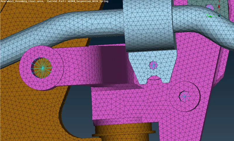
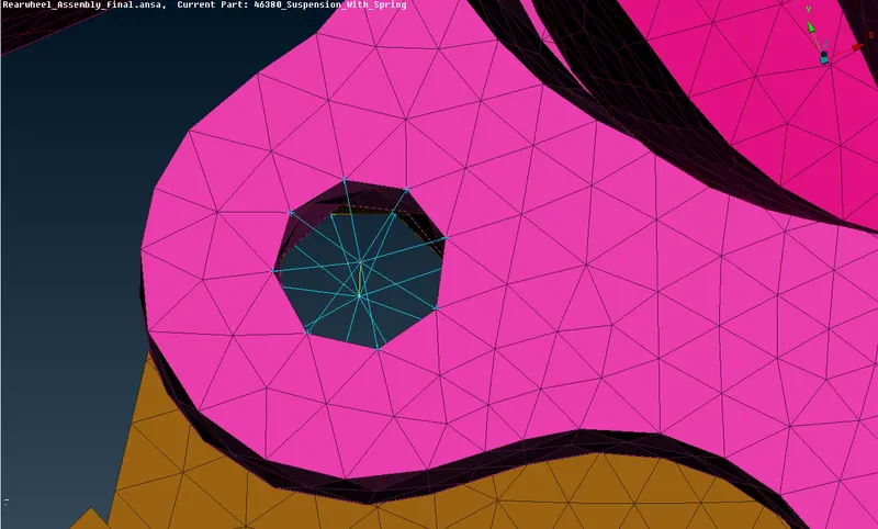
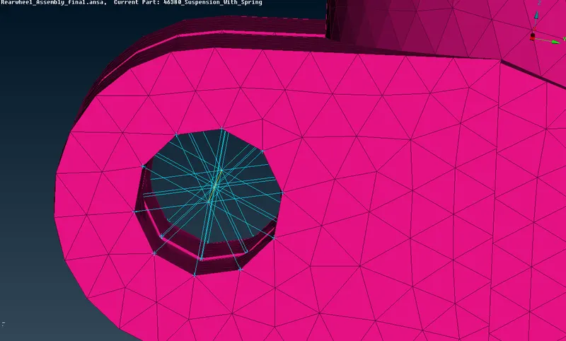
- Bolt connection is created between two component in order to give rigid connection and to remove the connection where ever required.
- Commonly in order to create a weld we need to create a point using the command Points `rarr`In cog option in topo module, since we are having only FE elements
- Then the point is converted Bolt points using the convert option.
- After that we need to realize the connection by selecting the Connection Selection Assistant in menu bar which prompt the user to select the parts which are needed to be bolted together
- In FE representation type Bolt is selected, with a search distance of 20 is given, also the body type is selected as RBE2
- After Inputing all the necessary paramaters we needed to realize the bolt connection.
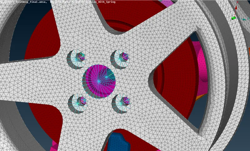
- RBE2 cluster connection between the wheel hub and the Rim
- RBE2 many node with 2 node stem body connection representing bolt connection.
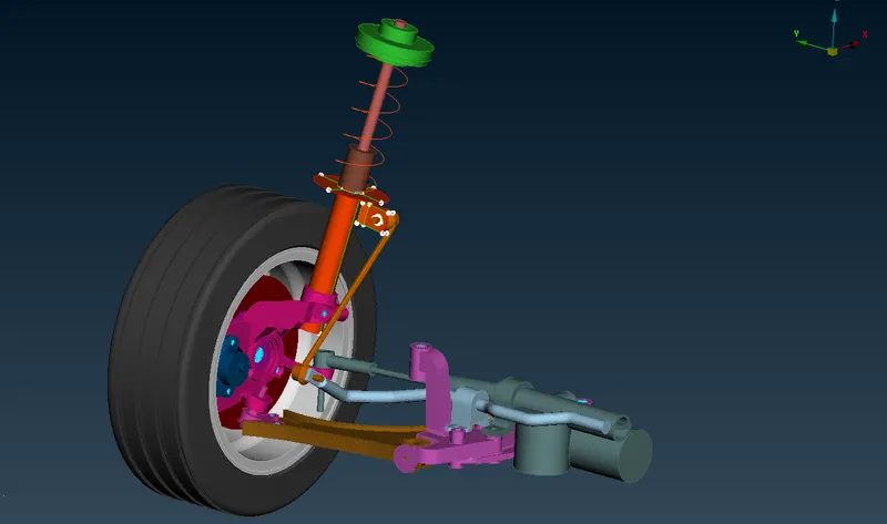
Final Model Image with connections
Transform option:
Once the meshing and the connection process has been completed, symmetry is performed on the model to have a complete image of suspension system, Transform[COPY]: This function is used to symmetry or mirror selected entities.
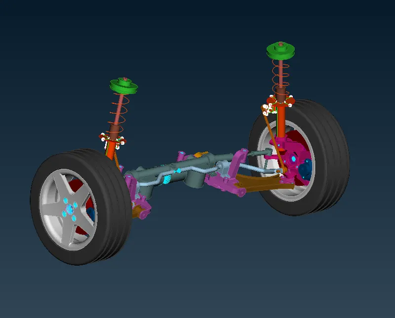
Full Assembly view
Learning outcomes:
- Geometric check and cleanup
- 1D, 2D and 3D meshing and mesh correction.
- Establishing connection between different components and different element types.
- Car suspension system and their purposes.
Conclusion:
Thus, the given component of the car suspension system model is checked for geometrical errors then meshed with 1D, 2D(shell) and 3D(solid) elements according to the given quality criteria and connection is implimented accordingly and finally transform option is done to get the complete suspension model.
Link for model: https://drive.google.com/file/d/1fsk-roqFJiubCfRnHsj4mQ6Fe5PxGRFu/view?usp=sharing