Project - 2 - Meshing on the suspension Assembly
OBJECTIVE :
To model the given rear wheel assembly with Solid elements and Shell elements by following the given quality criteria & assign proper thickness and connections to the assembly.
Given Quality Criteria :
Quality Criteria for Surface Meshing of Tyre and Rim (Element type: Tria) :
|
S.No |
Quality Criteria |
Value |
|
1 |
Target/Average length |
6.5 |
|
2 |
Minimum Length |
5 |
|
3 |
Maximum Length |
10 |
|
4 |
Skewness |
45 |
Quality criteria for Surface Meshing of Non Uniform thickness components other than Tyre and Rim (Element type: Tria) :
|
S.No |
Quality Criteria |
Value |
|
1 |
Target/Average length |
4 |
|
2 |
Minimum Length |
2 |
|
3 |
Maximum Length |
6 |
|
4 |
Skewness |
45 |
Quality Criteria for Volume meshing of all Non Uniform thickness components (Element type: Tetra Elements):
|
S.No |
Quality Criteria |
Value |
|
1 |
Tet-collapse |
0.2 |
Quality criteria for Mid surfacing of Uniform thickness part which has thickness less than 5 mm (Element type: Mixed elements) :
|
S.No |
Quality Criteria |
Value |
|
1 |
Target/Average length |
4 |
|
2 |
Minimum Length |
2 |
|
3 |
Maximum Length |
6 |
|
4 |
Aspect |
3 |
|
5 |
Warpage |
15 |
|
6 |
Skewness |
45 |
|
7 |
Jacobian |
0.7 |
|
8 |
Minimum Quad Angle |
45 |
|
9 |
Maximum Quad Angle |
135 |
|
10 |
Minimum Tria Angle |
30 |
|
11 |
Maximum Tria Angle |
120 |
WHEEL ASSEMBLY & ITS FUNCTIONS :
The wheel assembly consists of the following parts :
1. Tyre
2. Rims
3. Wheel Hub
4. Knuckle Arm
5. Shock Absorber
6. Suspension Spring
7. Brake Caliper
8. Brake Disc Rotor
9. Sway Bar
10. Tie Rod assy
11. Steering Mechanism
12. Drive Shaft
13. Control Frame
In general, all these parts together would be called as the wheel assembly. The Rear wheel assembly which is given here to model has Macpherson Strut suspension system in which the damper and the suspension spring were mounted directly to the Knuckle arm. The Rear wheel assembly which has several parts as discussed has seperate functions. The Suspension holds the major function of handling the road condition and also handling the driving condition inputs at various speeds and conditions. It has to keep the wheels in contact to the road despite the road condition at any given time as much as possible. It also prevents the vehicle body from irregular road surface which damages the vehicle body and the cargo while causing discomfort to the passenger. The design and type of suspension system would vary from a vehicle to vehicle based on its purpose and manufacturer. Thus, it is crucial that the suspension system holds the job of providing a diverse effect on ride quality and the handling characteristics of the vehicle which proves it to be a major part in the whole wheel assembly.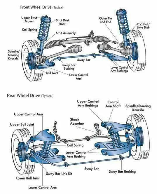
PROCEDURE :
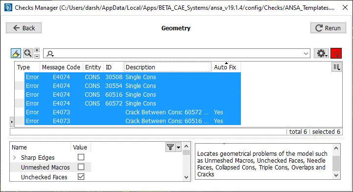
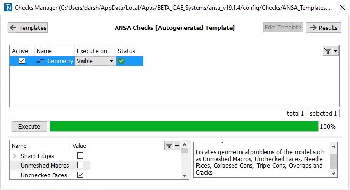
1. Firstly, Import the geometry and then check for any geometrical errors by using Checks >> geometry. Once the Model is free from any geometrical errors we can proceed with the further steps. Here is the given CAD model :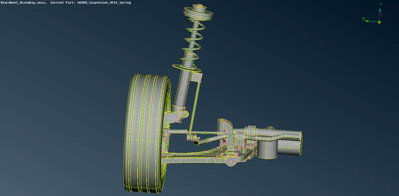
2. Now, since the component has numerous parts which are of different thickness and dimension, It is advised to carry out meshing for each and every part seperately. The given model has Rim, Tyre as seperate parts and all other parts in same PID as Suspension assembly. Now, Start with the rim and tyre. The Rim and Tyre were an uniform thickness part such that their quality criteria and mesh parameters were given. Firstly perform the Shell meshing on the Tyre. Remember to use Ortho Tria in places were there are curved surface and tria elements in flat surface. Set the perimeter and macros to target element size which is 6.5mm for tyre and rim. Now, go on with meshing.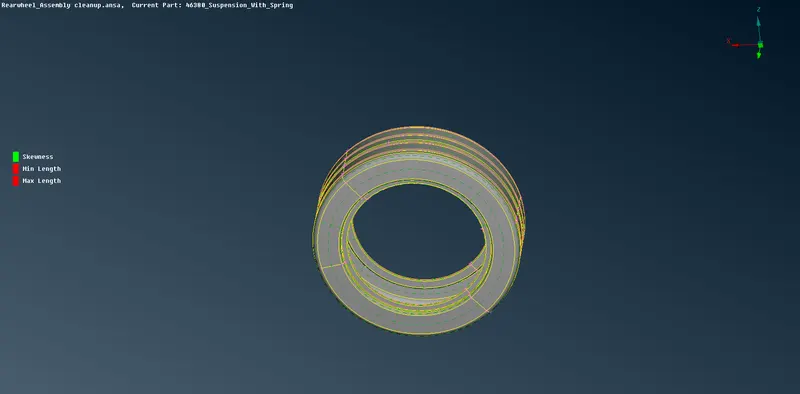
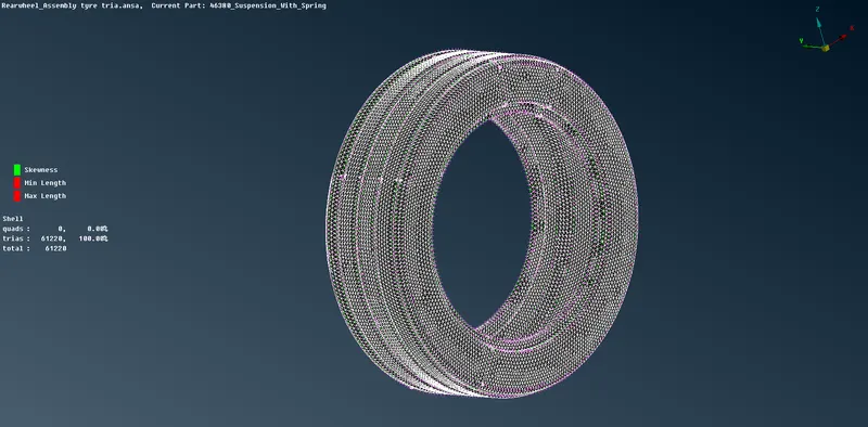
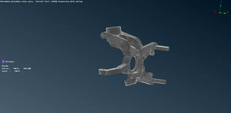
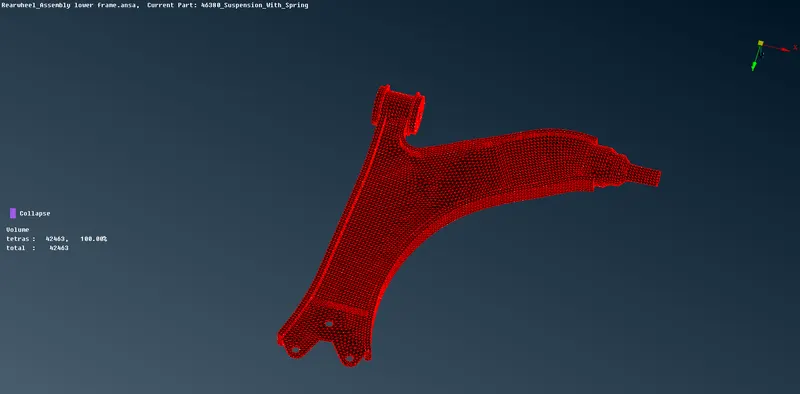
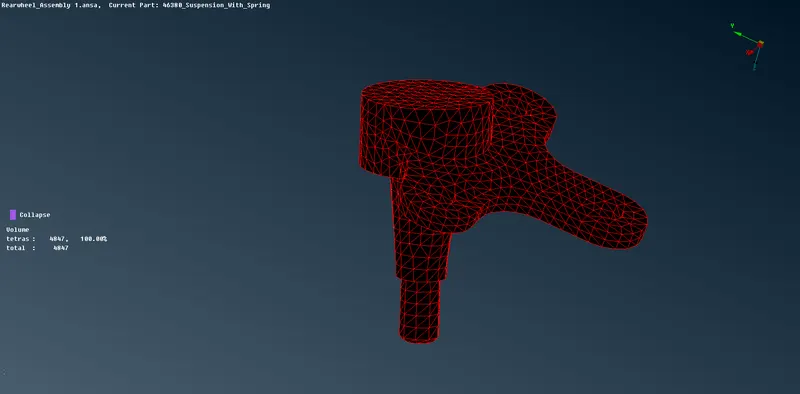
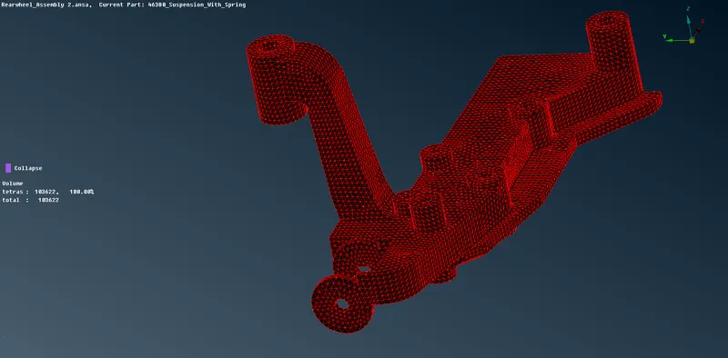
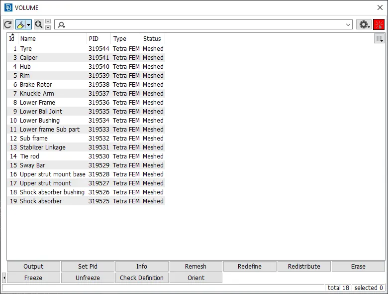
3. Once the shell elements are created and are free from failures, they can be used to deploy the solid elements. For creating Tetra elements, go to Volume mesh >> Define >> Select the entity. Now, go to Volume mesh >> List >> Select the entity listed >> Click Mesh >> Select Mesh type.
Here usage of Tetra FEM would get the task done precisely. Now, Check the quality criteria, for tetra elements the criteria to be followed is Tet collapse which is 0.2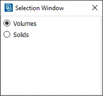
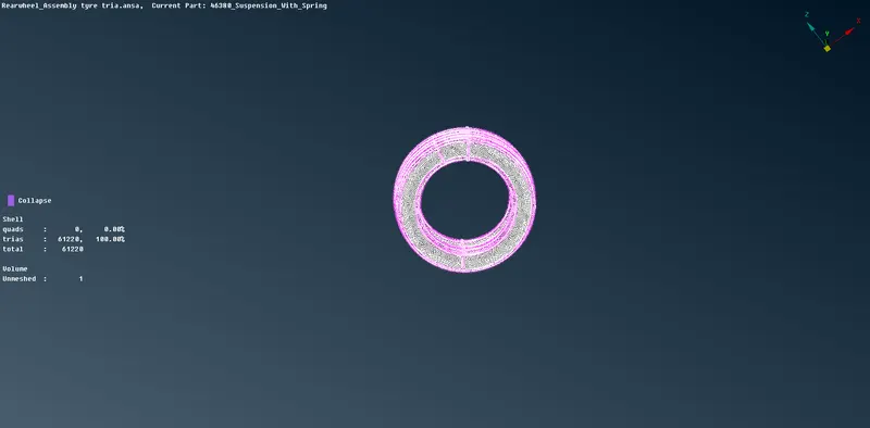
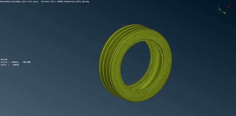
4. Now, we can follow the same procedure to mesh the rim since both needs to be meshed with similar parameters and quality criteria. Once the rim and tyre were meshed, we can now proceed with the further parts. All the other parts rather than the tyre and the rim has non uniform thickness in which some were lesser than 5mm ( Strut bar mount & Clamp ) which needs to be modelled with 2D shell elements while the others have seperate mesh parameters and quality criteria to be followed.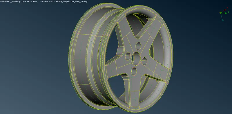
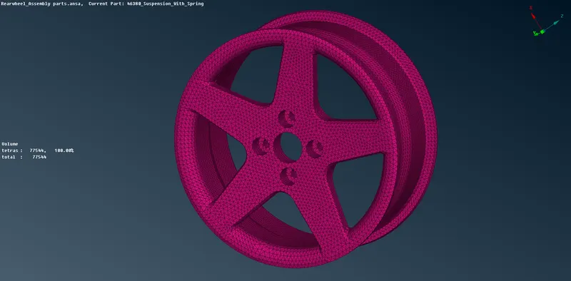
The other parts were meshed with 4mm tria elements as target size and then followed with respective quality criteria whereas the meshing procedure remains the same.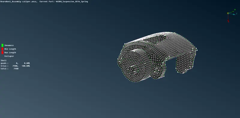
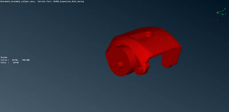
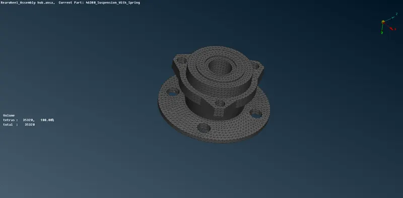
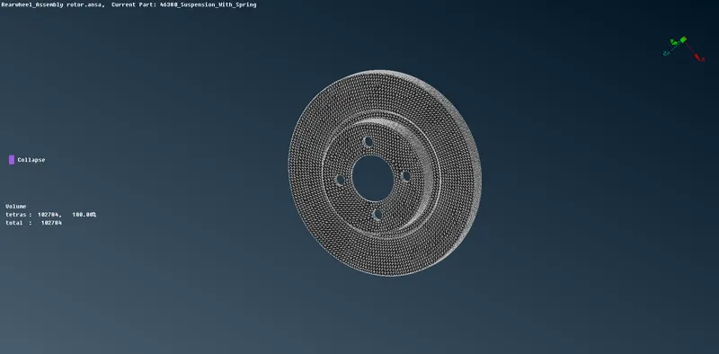
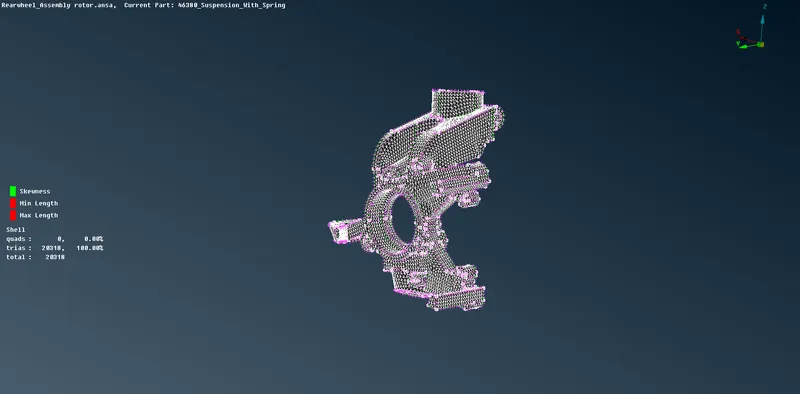
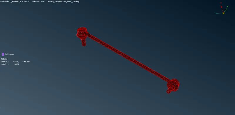
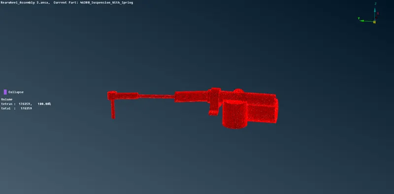
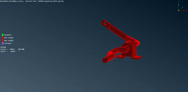
5. For the other parts ( Strut bar mount & Clamp ) which needs to be meshed with 2D shell elements, Midsurface has to be extracted manually and seperate PID should be set. The thickness of both the clamp and mount were found to be 3mm and the mesh parameters and quality criteria were followed respectively. 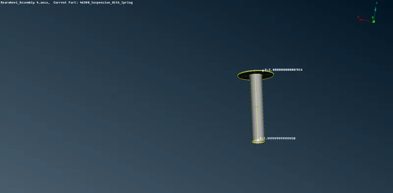
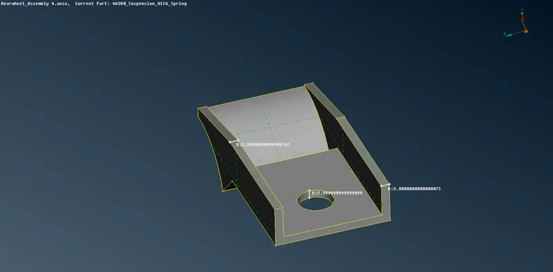
For midsurface, go to Topo >> Faces >> Offset >> select the surface >> Offset distance ( 1.5mm ). Once the offset is done for all the sides, extra surface other than the extensions were deleted and seperate PID's should be assigned with thickness value as 3mm. The Meshing can be done with target element size as 4mm along with the required quality criteria which is provided. 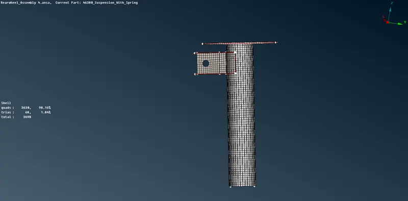
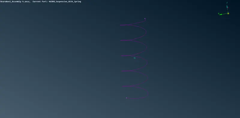
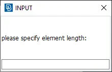
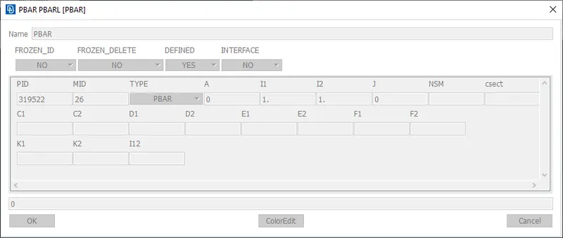
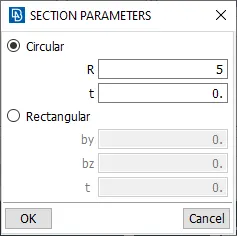
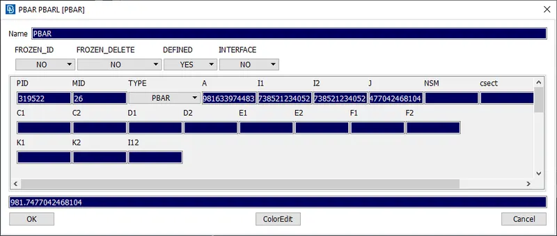
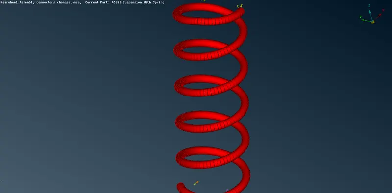
6. For the construction of Spring, we need to use 1D CBAR elements. For that we need to first create a curve such that it can be converted into CBAR elements. Go to Topo >> Curves >> Middle >> Select the surface lines in the spring and create the middle curve. Once the curve is created, Connect the multi curves into single curve. Curves >> Connect >> Multi >> select the curves >> Ok. Then, create the COG point for the curve and then go to Nastran Deck >> Elements >> CBAR >> Curve ( Box ) >> select the curve >> Element length (4mm target element size ). Now click on the COG point for the orientation and then PBAR creation window would open. Go to Area tab and click on (select from List) >> Enter the Radius as (5mm since the diameter of parent spring is 10mm). All the other entities would be calculated on its own. Now click Apply and Okay. We can see the PBAR elements created upon the curve.
To visualize the PBAR elements as solids, go to Quality criteria >> Presentation Parameters >> Draw Line elements Cross section >> As solids.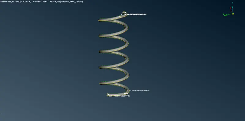
7. Since all the meshing part is done, we can now proceed with the Connections. For the connections, the Shell elements we've created ( Clamp and Mount ) we need to connect them with Seam weld connection, while all the other parts which has hole and shaft like intersection, all of them were connected with basic RBE2 connections with Many nodes and Two nodes type then and there required.
For Seam weld connection:
Go to Mesh >> Perimeters >> Feat2curve >> Select the edge of elements to be serving as the base for the seam weld.
Once the curve is created go to Convert >> Curves >> Seam line.
Now, go to connection manager >> Select the seam line >> select the parts P1, P2 ( Press F1 to modify and select the geometry to be welded ) >> Select FE type as ( Overlap Shell ) >> Enter search distance >> Select width distance ( 4mm target element size ) >> Double row type >> PID ( create new PID for the Weld elements ) >> Click Apply >> Realize. 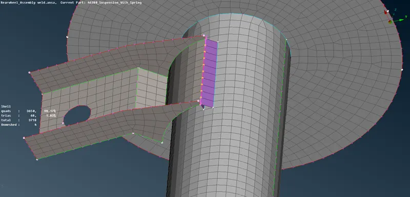
For other RBE2 Connections :
Go to Nastran Deck >> Elements >> RBE2 >> Many nodes >> Select the loop of nodes >> Middle click. Thus the RBE2 Cluster elements with master element in the middle would be formed. To represent the bolt length, we can use Two node RBE2 between the master nodes of two cluster RBE2 elements.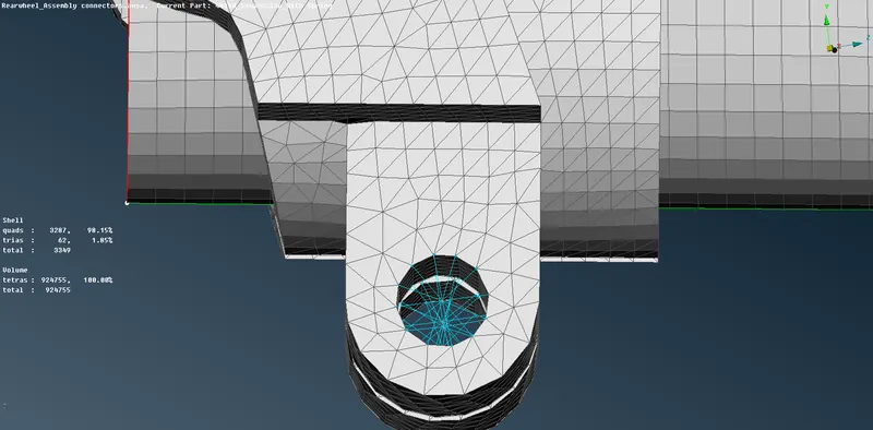
The spring and the strut bar mount can be connected with such Two noded RBE2 elements. Nastran deck >> Elements >> RBE2 >> Two nodes >> select the nodes >> Middle click to create the connection.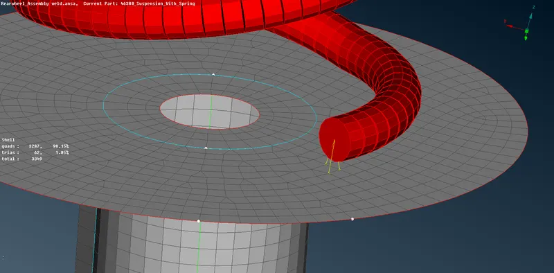
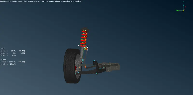
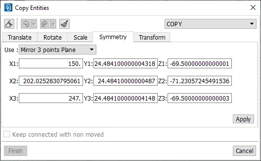
Once all the connections were done, The complete geometry has to be reflected to the symmetry plane so as to complete the process. Now, to reflect the entities,
Go to Transform >> Entities >> Select the whole entities >> Click Copy >> Now, select the Symmetry option >> Use >> Mirror 3 point plane.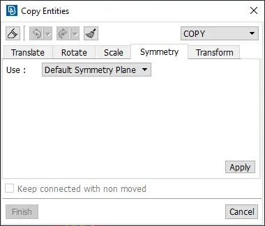
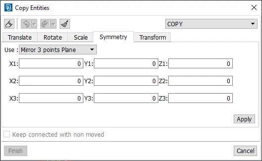
Now, select the point from top, middle and the bottom of the surface elements ( surface from where the mirroring would happen ) Once all the three points are selected, Click Apply and check the Mirroring. If it is correct, then click the Finish option to accept the mirroring.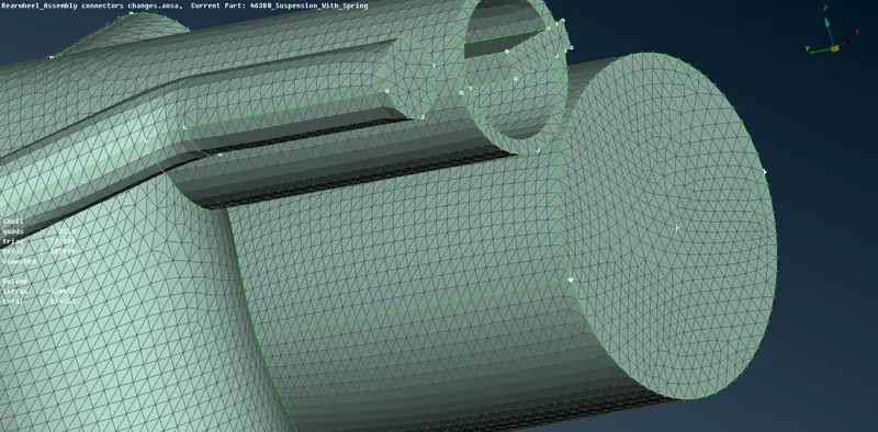
RESULT :
Thus, the complete meshing of the Rear wheel assembly and its connection were done successfully.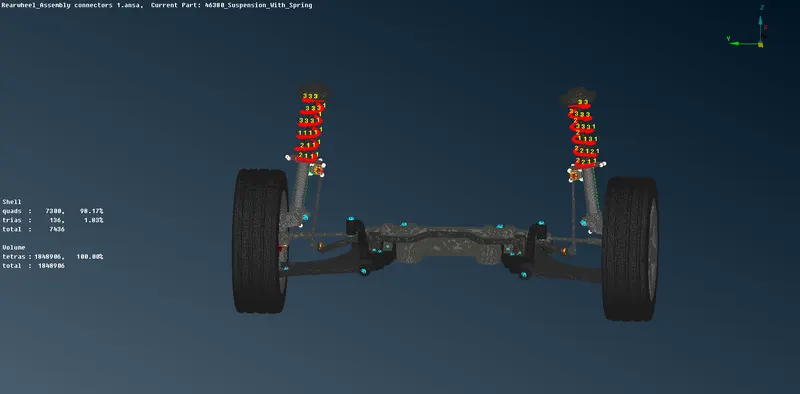
INFERENCE :
1. Volume meshing of complicated parts.
2. Clearing failures of tetra elements.
3. Deploying connections for all the components.
4. 1D modelling of the Spring.
NOTE :
The Element length and quality criteria should be adjusted accordingly since there were more number of components which are of various dimensions. Seperate PID can also be created to avoid any confusions.