Project - 2 - Meshing on the suspension Assembly
1. AIM: Do a Meshing of the suspension Assembly and Establish an applicable connection.
2. OBJECTIVES OF PROJECTS:
For the given assembly, check for the geometrical errors and mesh with the given element Quality criteria. After meshing the component the thickness has to be assigned for mid surfaces. Use tetra elements to model non-uniform thickness components. Also use Appropriate connections to connect the component.
Common Note:
- Use Volume mesh for Tyre and Rim with below Quality criteria. (Use Tria Element)
- Use mid surface only when the thickness is uniform and less than 5 mm. (Use Mixed elements)
Quality Criteria for Surface Meshing of Tyre and Rim (Element type: Tria) :
|
S.No |
Quality Criteria |
Value |
|
1 |
Target/Average length |
6.5 |
|
2 |
Minimum Length |
5 |
|
3 |
Maximum Length |
10 |
|
4 |
Skewness |
45 |
Quality criteria for Surface Meshing of Non Uniform thickness components other than Tyre and Rim (Element type: Tria) :
|
S.No |
Quality Criteria |
Value |
|
1 |
Target/Average length |
4 |
|
2 |
Minimum Length |
2 |
|
3 |
Maximum Length |
6 |
|
4 |
Skewness |
45 |
Quality Criteria for Volume meshing of all Non Uniform thickness components (Element type: Tetra Elements):
|
S.No |
Quality Criteria |
Value |
|
1 |
Tet-collapse |
0.2 |
Quality criteria for Mid surfacing of Uniform thickness part which has thickness less than 5 mm (Element type: Mixed elements) :
|
S.No |
Quality Criteria |
Value |
|
1 |
Target/Average length |
4 |
|
2 |
Minimum Length |
2 |
|
3 |
Maximum Length |
6 |
|
4 |
Aspect |
3 |
|
5 |
Warpage |
15 |
|
6 |
Skewness |
45 |
|
7 |
Jacobian |
0.7 |
|
8 |
Minimum Quad Angle |
45 |
|
9 |
Maximum Quad Angle |
135 |
|
10 |
Minimum Tria Angle |
30 |
|
11 |
Maximum Tria Angle |
120 |
3. BODY OF CONTENT:
Let's go with step by step,
- IMPORTING THE MODEL: Importing the given model 'Rearwheel_Assembly.ansa'.
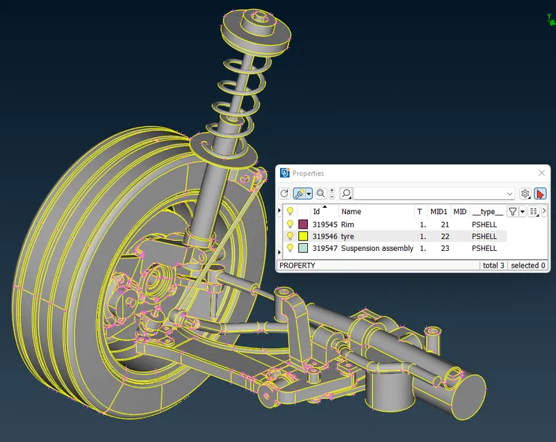
Image 01: Rearwheel_Assembly.ansa
- CREATE A PID: From above image we can see there are total three properties comes with model. But that's not enough, because Suspension assembly has a many component. And Each component has to be in a different PID to generate volume mesh, mid-surface or to establish a connection. So, only a 'manual method' is possible to extract each component and give a new PID using a 'Set-PID' option. But here before going with the manual, I got Something in my mind and I checked it in the 'Model browser'. And Yes I gotted all parts in individual form (see image 02). So, its save a more time for me. And then using a 'Model browser' All parts separated successfully in less time(see image 03).
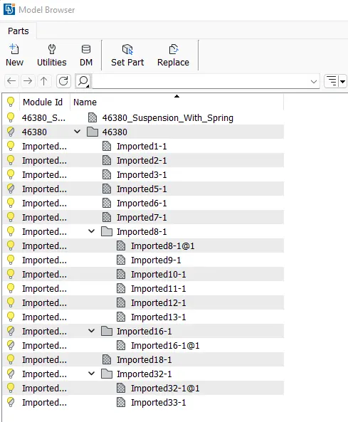
Image 02: Individual component in Model browser.
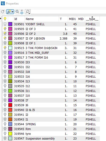
Image 03: Each Component PID generated
- GEOMETRY ERROR:
After component separation now to do a geometry check. So, I checked and found ok
- THICKNESS MEASUREMENT:
While measuring a thickness most of parts has a variable thickness or thickness is greater then the 5mm.
- GENERATING A VOLUME MESH:
To generate a volume mesh first we have to generate a mesh on the component's surface. So, As per the given criteria a mesh is generated. Now the ANSA is able to detect a volume area, So using a path 'VOLUME MESH MODULE' > 'Define' a volume is defined. So, using a 'Unstructured mesh' > ' Tetra FEM' a mesh is generated as. Can see in the below image
Currently I learn two functions to generate a 'Unstructured mesh', 'Tetra rapid' mesh & 'Tetra FEM' mesh. where the 'Tetra rapid' function generates only the Tetra element. and 'Tetra FEM' is used its generate a tetrahedral mesh or quad elements based on the types of the element present on the surface. But For this assembly both are ok to giving same results.
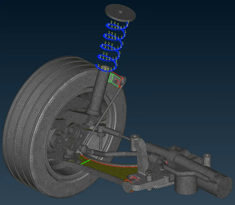
Image 04: Volume mesh generated
- GENERATING A 2D MESH:
In this assembly I found only 1 part in the sheet metal form. And meshed it within quality criteria(can see in below image).
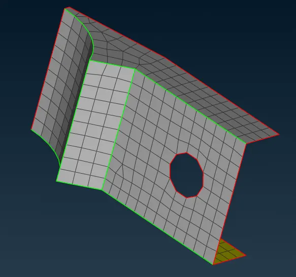
Image 05: 2D-mesh generated
- SUSPENSION SPRING :
Using a Middel, Cons2curve and CBAR function a spring is generated. can be see in below image,
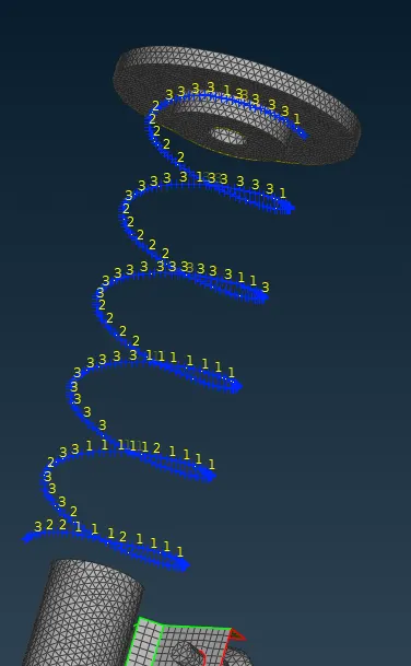
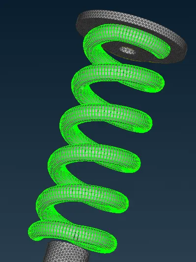
Image 06: Line element type & As a solid
- DEFINING A CONNECTIONS :
As per me there a fixed and hinged type connection is needed to establish.
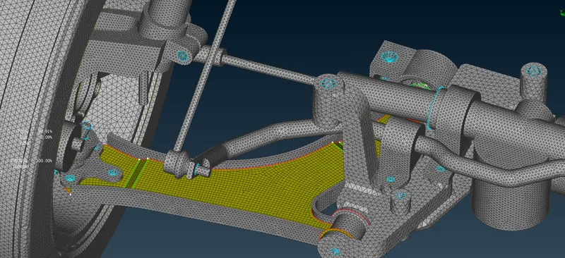
Image 07: Established some fixed and rotationally free connection generated in suspension assembly.
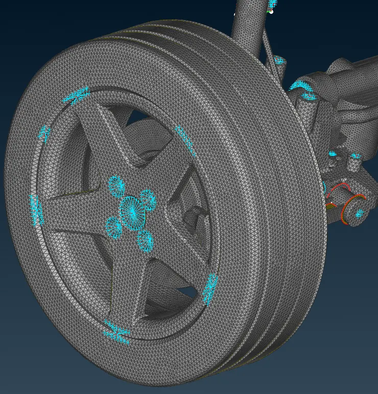
Image 08: Established some fixed connections between Rib and Tyre.
4. LEARNING OUTCOMES:
This project is a very challenging task for me, because This is a combined task at the same time where there are 2d mesh, 3D mesh & its connections also needed to generate. Here is a deal to manage all parts with its PID & quality criteria. Sometimes a time is spent in order to find the right function to do the right operation so, we have to be as aware as possible with all the functions of ANSA to establish a good skill on ANSA. Time taken for this project is as per below.
1 hr for seperating component
10 min for geomatery clenup
4 he for V.Mesh generation
1.5 hr rechecking the entire model and corrected
3.5 hr tried to correct some mistake, but not solved
Total : 10 hr
5. CONCLUSION:
I conclude from this project that to finish a task on time, you have to be clear in your mind which process to do in which part. And also need to keep a save file with the save as with the new name, to bring back a previous model if something wrong happened. In my case, one last time can not recover a deleted part in its initial shape.