Project - 2 - Meshing on the suspension Assembly
AIM
To perform shell meshing and also volume meshing along with the necessary connections for the given Suspension system model.
OBJECTIVE :
For the given assembly, check for the geometrical errors and mesh with the given element Quality criteria. After meshing the component the thickness has to be assigned for mid surfaces. Use tetra elements to model non-uniform thickness components. Also, use Appropriate connections to connect the component (Use PBAR elements to model suspension spring). At last, perform the Symmetry command to reflect the half-finished model to the other side.
THEORY:
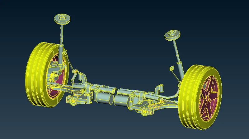
The suspension system is made up of several components, including the chassis, which holds the cab of the car. The springs support the vehicle weight and absorb and reduce excess energy from road shocks, along with the shock absorbers and struts. Finally, the anti-sway bar shifts the movement of the wheels and stabilizes the car.
Suspensions parts: The suspension of a car is actually part of the chassis, which comprises all of the important systems located beneath the car's body. These systems include:
- The frame - structural, load-carrying component that supports the car's engine and body, which are in turn supported by the suspension
- The suspension system - a setup that supports weight, absorbs and dampens shock and helps maintain tire contact
- The steering system - the mechanism that enables the driver to guide and direct the vehicle
- The tires and wheels - components that make vehicle motion possible by way of grip and/or friction with the road.
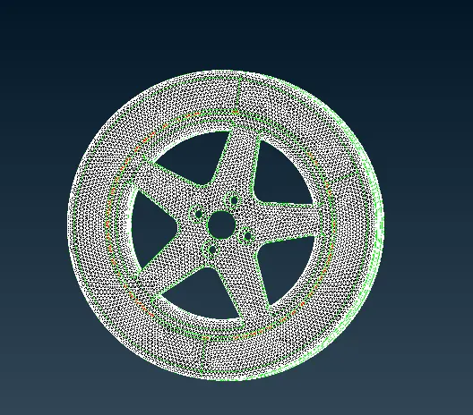
Quality Criteria for Surface Meshing of Tyre and Rim (Element type: Tria) :
|
S.No |
Quality Criteria |
Value |
|
1 |
Target/Average length |
6.5 |
|
2 |
Minimum Length |
5 |
|
3 |
Maximum Length |
10 |
|
4 |
Skewness |
45 |
Quality criteria for Surface Meshing of Non Uniform thickness components other than Tyre and Rim (Element type: Tria) :
|
S.No |
Quality Criteria |
Value |
|
1 |
Target/Average length |
4 |
|
2 |
Minimum Length |
2 |
|
3 |
Maximum Length |
6 |
|
4 |
Skewness |
45 |
Quality Criteria for Volume meshing of all Non-Uniform thickness components (Element type: Tetra Elements):
|
S.No |
Quality Criteria |
Value |
|
1 |
Tet-collapse |
0.2 |
Quality criteria for Mid surfacing of Uniform thickness part which has thickness less than 5 mm (Element type: Mixed elements) :
|
S.No |
Quality Criteria |
Value |
|
1 |
Target/Average length |
4 |
|
2 |
Minimum Length |
2 |
|
3 |
Maximum Length |
6 |
|
4 |
Aspect |
3 |
|
5 |
Warpage |
15 |
|
6 |
Skewness |
45 |
|
7 |
Jacobian |
0.7 |
|
8 |
Minimum Quad Angle |
45 |
|
9 |
Maximum Quad Angle |
135 |
|
10 |
Minimum Tria Angle |
30 |
|
11 |
Maximum Tria Angle |
120 |
PROCEDURE:
Importing a Model & Geometry Cleanup :
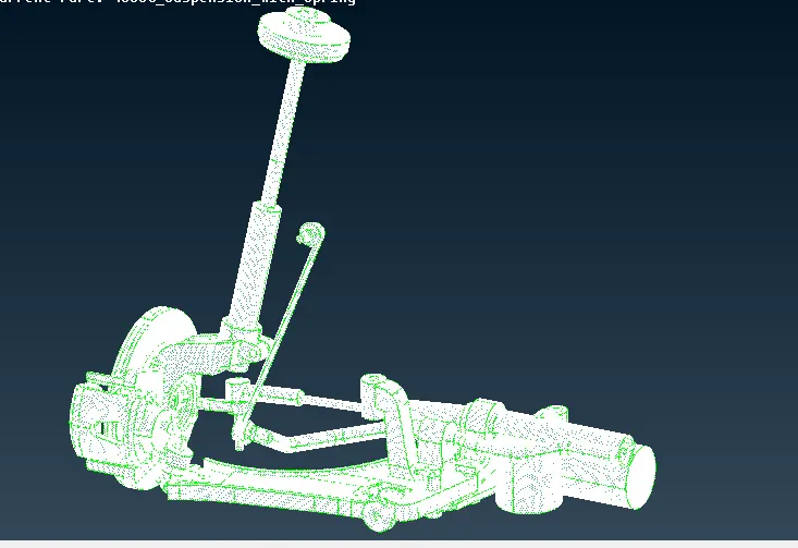
1. Import the given model by using the File-->open option.

Fig: Rear Suspension Model
2. Go to Topo-->Faces-->Topo option and select all CONS and Click ok to stitch all CONS with each other.
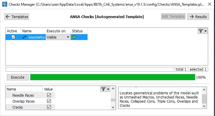
3. Go to Tool-->Checks-->Geometry for Geometry Clean up.
4. In the above Checks Manager window click Execute to check any error occurred in the Model and fix the Error and Cleanup the Geometry.
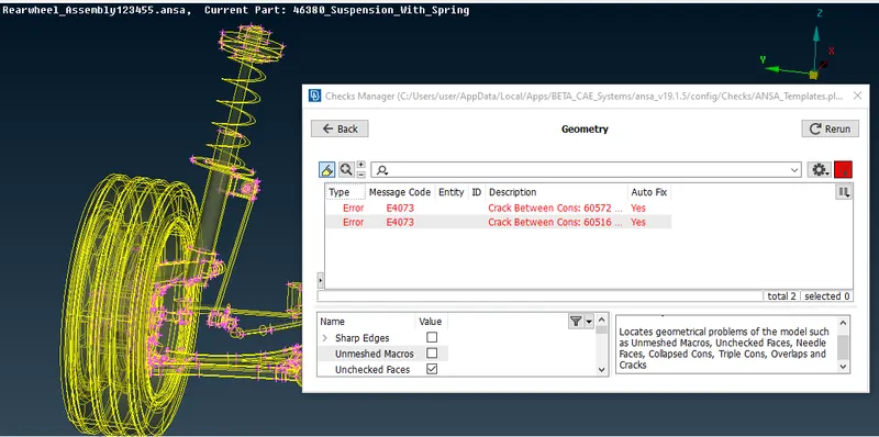
5. The topological errors have been fixed by using fix option
MIDSURFACING:
As this model is a compilation of different parts having different thicknesses, all parts can not be mid-surfaced. Parts with less than 5mm thickness are only mid-surface. The component for which mid-surface is taken is shown below.
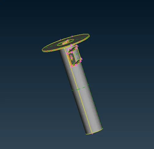
These are the parts for which mid surface is taken as they have uniform thickness and also less than 5mm. They are mid-surfaced using the manual offset method and their respective thickness' assigned properly.
2D MESHING
1. Set the given Quality Criteria for the Component.
2. Go Utilities-->Quality Criteria-->Shells Option and assign the given Quality Criteria Values.
QUALITY CRITERIA SETUP:
We must assign quality parameters such that meshing elements will get measured from their ideal shape. The parameters like warping, skewness, aspect ratio, etc.. have to be given in the quality criteria setup. meshing parameters also have to give before meshing such that surface will get mesh under given length.
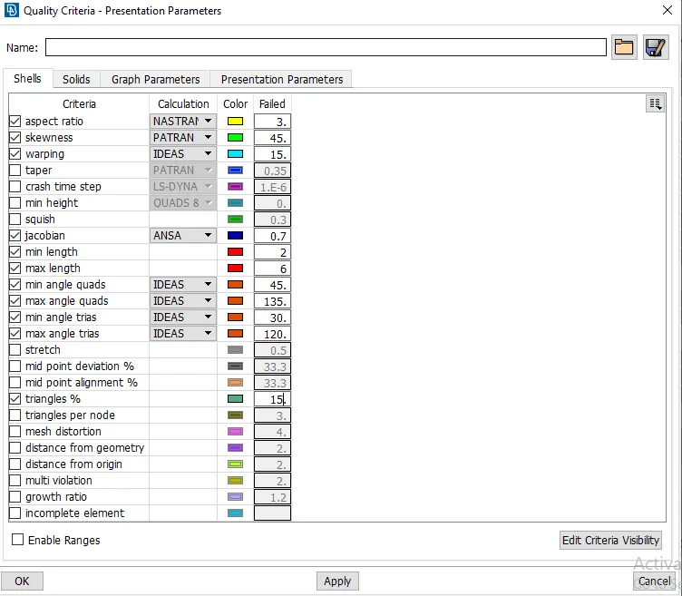
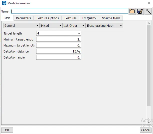
Quality criteria Mesh parameters
3.Go to Mesh-->Perimeters--> Length Option and Select the Component to Mesh and enter the Value of Perimeter Length and Macro Length for Meshing.
4.Go to Mesh-->Mesh Generation Option and Select the Mesh type to mesh the component.
5.Select the Mesh type in the Mesh generation and Select the Faces to mesh and Mesh will be generated.
6.Use Shell Mesh-->Reconstruct option to rearrange the Mesh and Use Shell Mesh-->Smooth Option to arrange Mesh lines equally within the Selected Surface and solving the Quality criteria issues.
7. Use Grids-->Paste or Elements-->Split / Swap / Joint Option to eliminate or reduce the trias and get better mesh flow.
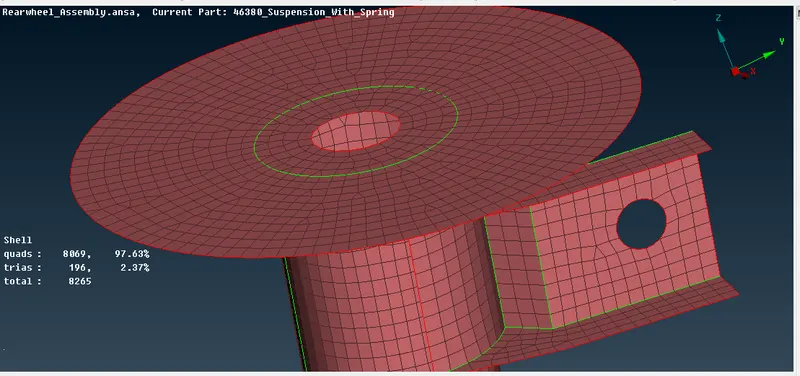
As it can be observed, the mid-surface has been taken and also meshed according to the given quality criteria. Mixed type is selected for meshing and trias are removed as much as possible.
3D MESHING:
For the 3D elements, the only quality criteria is that of tetra-collapse with a value of 0.2. We start with the components excluding the tire and rim. In order to volume meshing, the surface mesh has to be deployed on all the sides and they have to be mapped from one side to another.
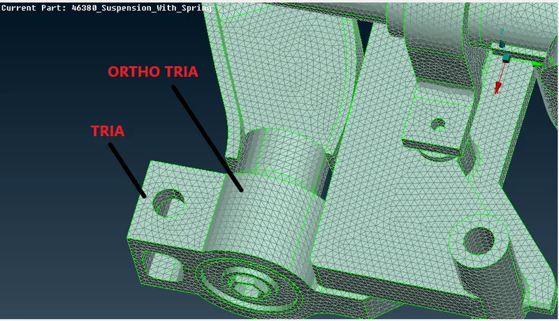
We start meshing with ortho-tria elements for the curved regions and use tria elements for the other regions. We use spot mesh for this surface meshing. After meshing all parts which require the surface mesh excluding the tire and the rim, are meshed completely and the focus is shifted towards the tire and the rim. For this, we go the mesh parameters and the quality criteria to reassign the new values given for the tire and rim and proceed with the same steps followed for the other parts.
AFTER MESHING:
Change the Quality criteria & Mesh Parameters for Surface Meshing of Non-Uniform thickness components for Tyre and Rim and Mesh the Component.
VOLUME MESH/ 3D MESH:
Once the surface mesh is deployed we can proceed to the volume meshing.
Volume mesh module > Volumes > Define > Manual
For defining a volume we have already meshed macros or FE-model mesh. After defining the shell mesh in the Volume module we need to select the List options from the Volume options in the same Volume mesh module. Volume mesh module > Volumes > List. Here we need to select the undefined shell mesh part in the volume module and right-click on it for defining a Solid PID for the solid meshing process and continue with the Solid mesh with any two types which are mentioned below:
Tetra Rapid:
- The Tetra Rapid algorithm meshes the volume with Tetra Elements.
- The maximum growth rate, which is the approximate growth factor of volume element size from layer to layer while the generation moves towards the interior of the volume.
- With the specified inputs from the user like the maximum and minimum value of the tetra elements which specify the growth rate factor.
Tetra FEM:
- This function automatically creates a Tetrahedral mesh inside selected volumes.
- It is to be used mainly for structural applications and the volumes to have meshed with this function must have been defined using the Define(Volumes) function.
if there are any off elements(collapse) is present and eliminate the off elements. Go to Mesh-->Grids-->MV Free option and select the nodes and move in x,y,z, direction to clear the quality issue.
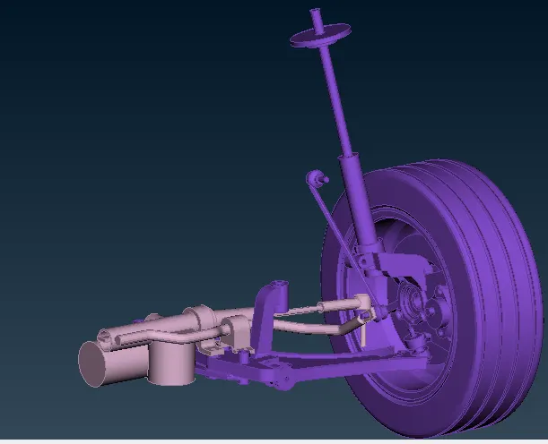
FIG: Volume meshing for remaining components in the suspension system
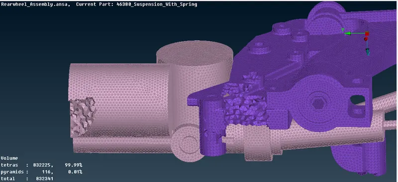
It is made sure that no kinks or raised dips are present in the FE model. If present, they are removed manually by using the MV Free option. The quality violating elements are remeshed again to achieve good quality by using reconstruct option.
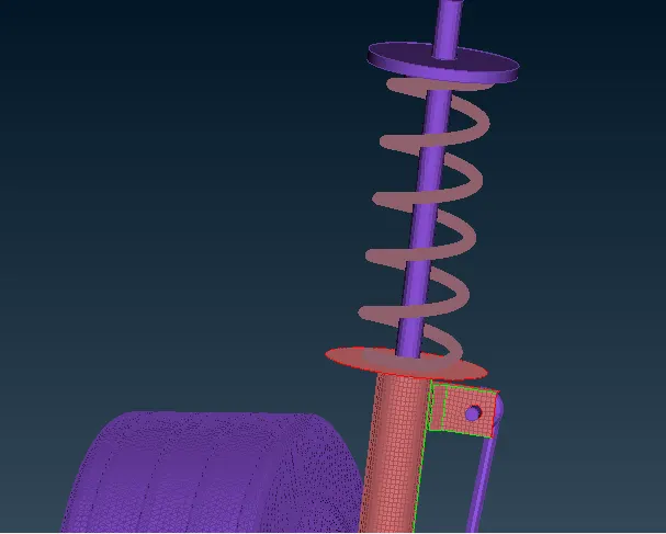
1D Element Representation for Spring :
- Convert the Spring into a single curve which should pass through the axis of it using the following steps: Topo module > Curves > Middle.
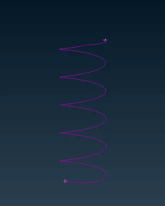
- After Creating a curve, Go to NASTRAN DECk-->Elements-->CBAR option and Select the Curve to convert into a CBAR curve.
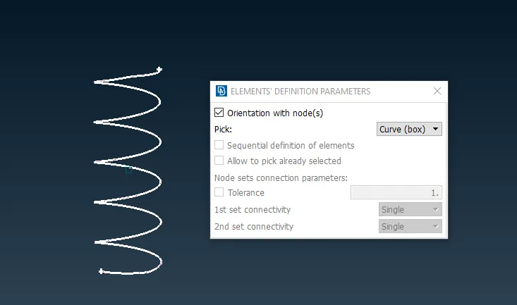
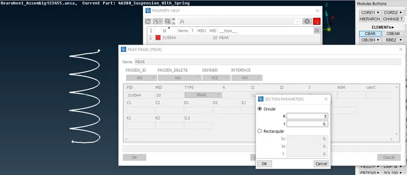
-
create a new PID and Define Area by giving a Radius of Spring, i.e. Cross Section radius of spring, assign the radius of spring and it will automatically calculate the remaining necessary things.
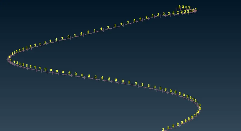
1d Elements has been created using CBAR option which is shown below
CONNECTIONS:
After meshing we have to give connections for the required components. There are different types of connections deployed across the mesh depending on the requirements. Bolt connection is deployed in the region where two or more components are bolted/attached together. Cluster RBE2 is deployed for rigid required mechanisms. In 2D mesh, when the RBE2 connection for the bolt is deployed, a zone cut is made to add for the washer element deployed for the spider. For connections, we use the NASTRAN deck present after the volume mesh module.
Go to NASTRAN DECK-->Elements-->RBE2 option and select the nodes and Create an RBE2 Connection.
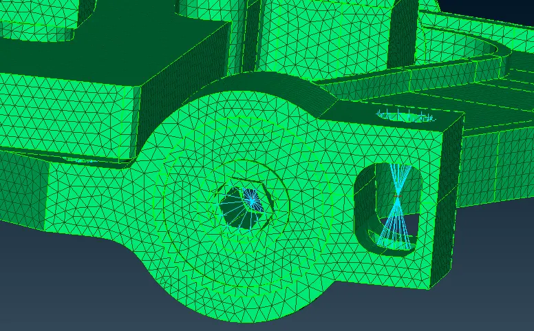
FIG: Cluster RBE2
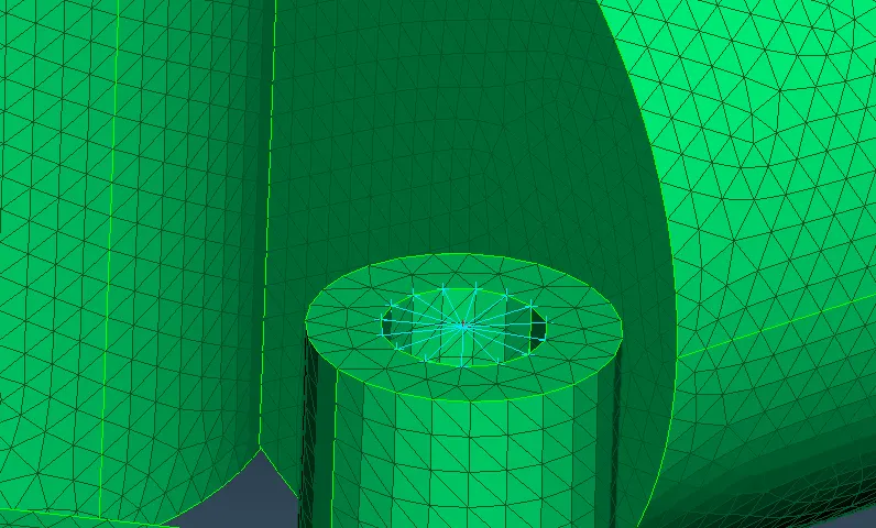
FIG: SPIDER RBE2
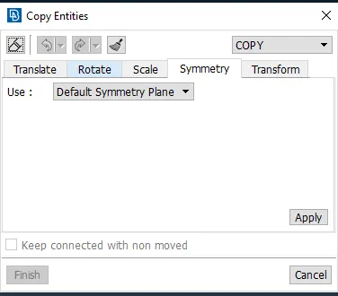
Transform Option
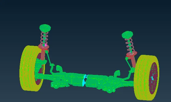
After all the meshing and connections have done, performed symmetry on the model to have a complete picture of the suspension system Transform [COPY]: This function is used to Symmetry or Mirror selected entities (Faces, Points, Elements, etc).
RESULT:
CONCLUSION:
Thus the suspension model has meshed with 1D elements, 2D shell elements, and 3D tetra elements according to quality criteria. Connections are performed wherever it's required.
LEARNING OUTCOMES:
1. Learned to work on complex geometries such as suspension assembly.
2. learned to generate mid surface by offset surface, also learned to identify those components where the mid surface is required.
3. learned to generate volume mesh by different means, moreover learned to remove 'tet collapse' from volume mesh.
4. Learned to establish different connections in the required areas.