Project - 2 - Meshing on the suspension Assembly
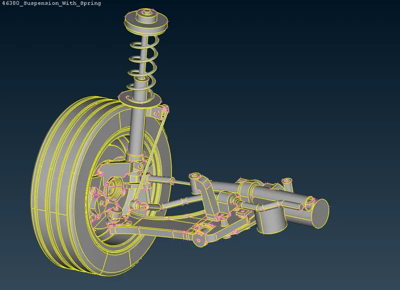
Aim:- Mesh generation and deploying connections for car rear suspension assembly.
Objective:-
* Perform geometry cleanup.
* All the 2D and 3D elements should clear the given quality criteria.
* Give appropriate connection for rear suspention assembly model.
* Quality parameters for all the components are:
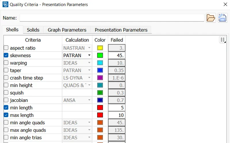
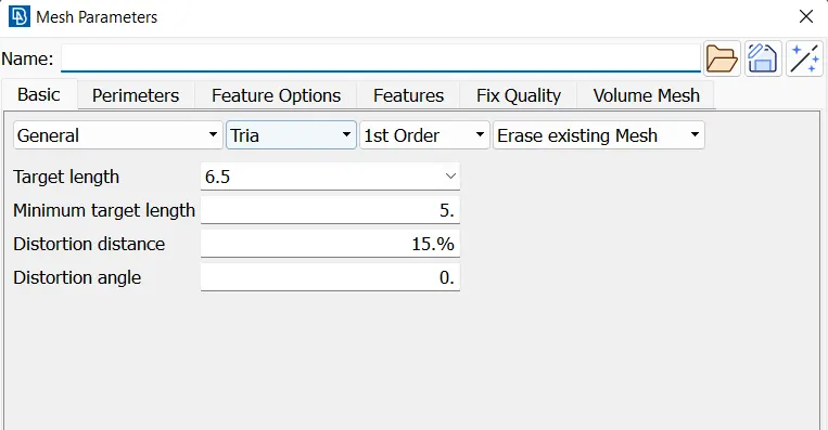
Quality Criteria for Surface Meshing of Tyre and Rim (Element type: Tria) :
|
S.No |
Quality Criteria |
Value |
|
1 |
Target/Average length |
6.5 |
|
2 |
Minimum Length |
5 |
|
3 |
Maximum Length |
10 |
|
4 |
Skewness |
45 |
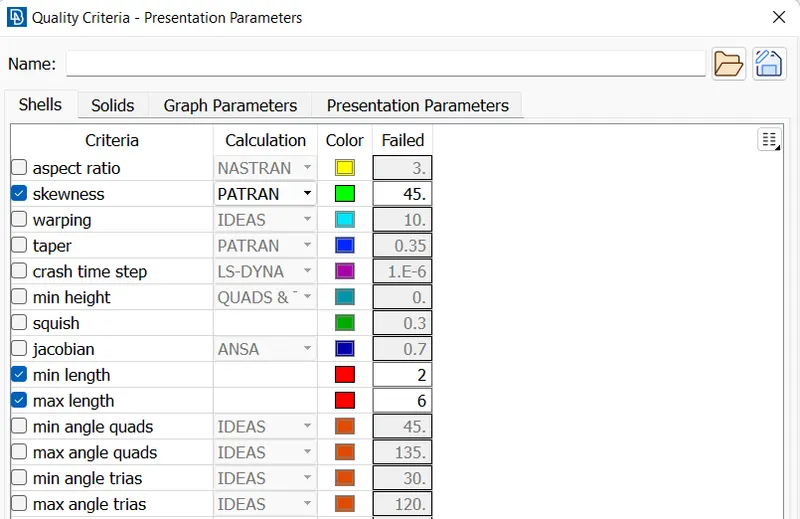
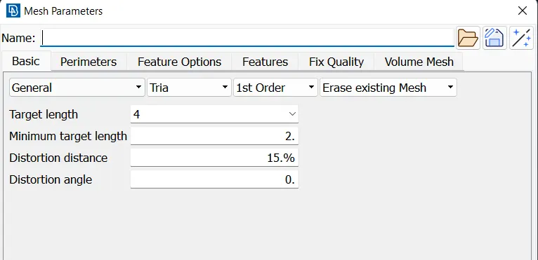
Quality criteria for Surface Meshing of Non Uniform thickness components other than Tyre and Rim (Element type: Tria) :
|
S.No |
Quality Criteria |
Value |
|
1 |
Target/Average length |
4 |
|
2 |
Minimum Length |
2 |
|
3 |
Maximum Length |
6 |
|
4 |
Skewness |
45 |
Quality criteria for Mid surfacing of Uniform thickness part which has thickness less than 5 mm (Element type: Mixed elements) :
|
S.No |
Quality Criteria |
Value |
|
1 |
Target/Average length |
4 |
|
2 |
Minimum Length |
2 |
|
3 |
Maximum Length |
6 |
|
4 |
Aspect |
3 |
|
5 |
Warpage |
15 |
|
6 |
Skewness |
45 |
|
7 |
Jacobian |
0.7 |
|
8 |
Minimum Quad Angle |
45 |
|
9 |
Maximum Quad Angle |
135 |
|
10 |
Minimum Tria Angle |
30 |
|
11 |
Maximum Tria Angle |
120 |
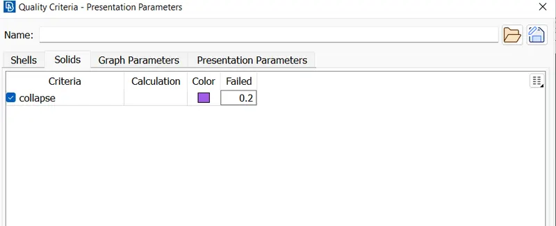
Quality Criteria for Volume meshing of all Non Uniform thickness components (Element type: Tetra Elements):
|
S.No |
Quality Criteria |
Value |
|
1 |
Tet-collapse |
0.2 |
2) Segregate the component:-
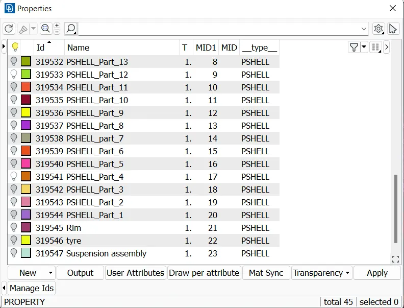
* For better handling and meshing parts separately we shoud have to segregate the model into different - different PID's so we work on parts separately.
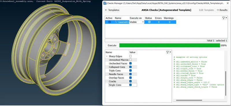
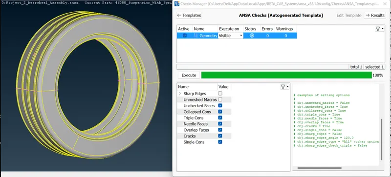
* In this way we do geometry checkup for all the components.
3) Mid Surface Generation For Uniform thickness part which has thickness less than 5 mm :-
* Measure the thickness:
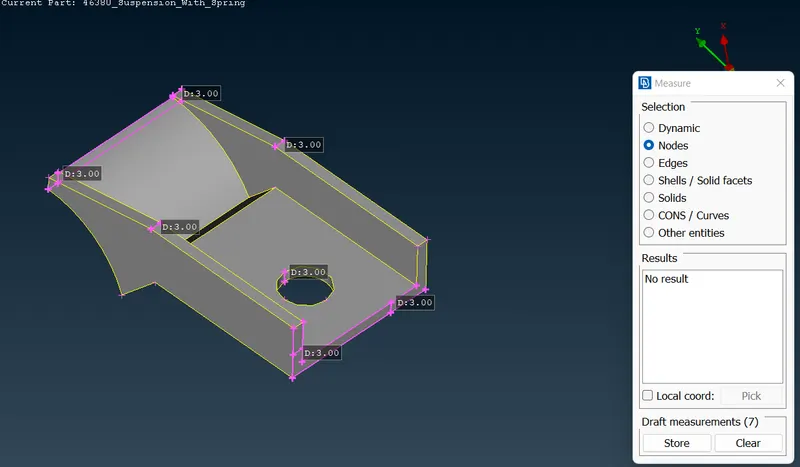
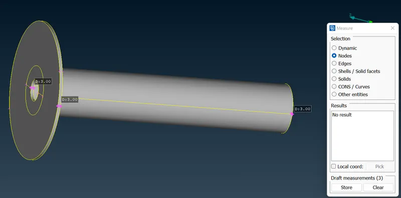
* In above image we can see that the thickness of parts is uniform.
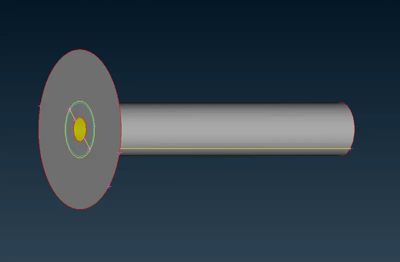
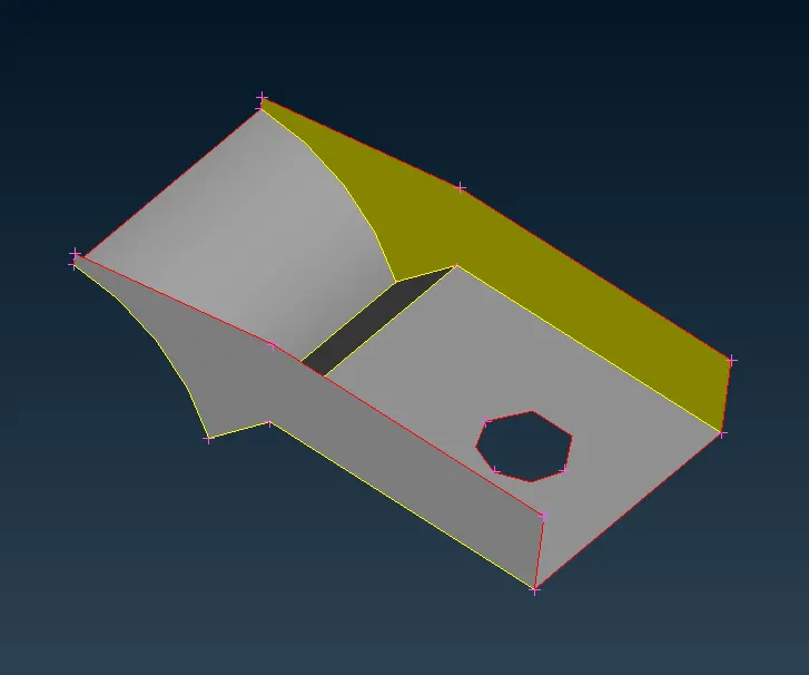
* For extracting the mid surface for these parts we use offset method and extract mid surface.
4) Set Quality Criteria and Mesh parameters:
1. For Tyre And Rim ( for surface meshing )
2. For parts other than Tyre And Rim ( for surface meshing )
3. For uniform thickness parts ( for 2D meshing )
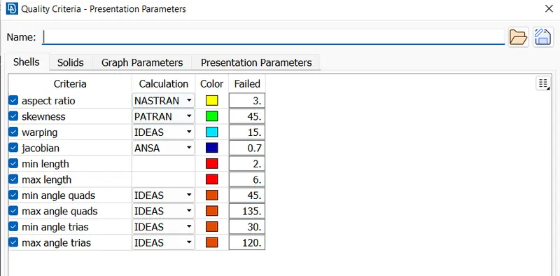
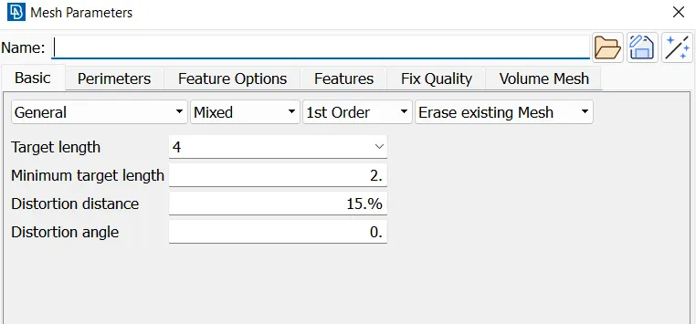
* 3D quality criteria for all components
5) MESHING
* Surface Meshing :-
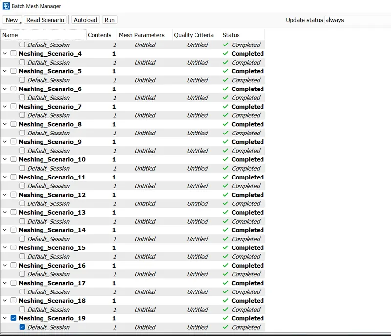
* For surface meshing we use Batch mesh method.
* First we set the component in new part and then open batch mesh manager and mesh the component.
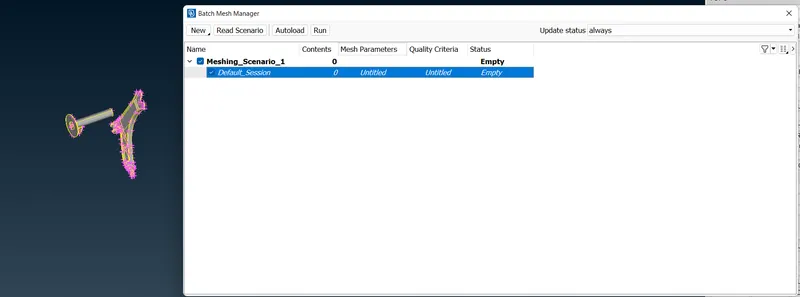
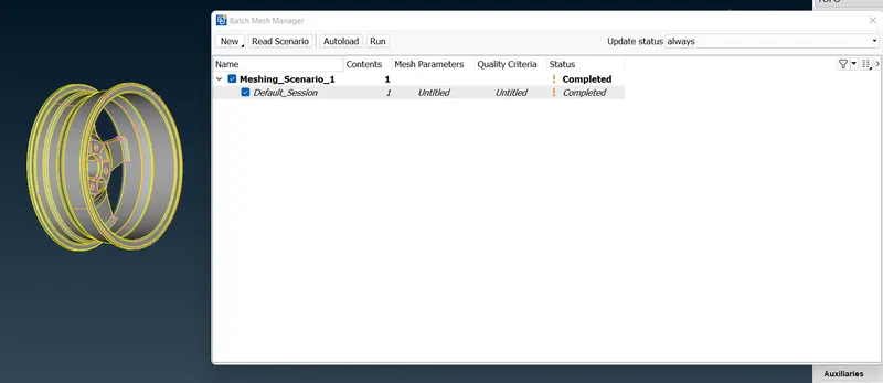
* In this way we done shell meshing in all the parts and clear the quality criteria with use of different tools.
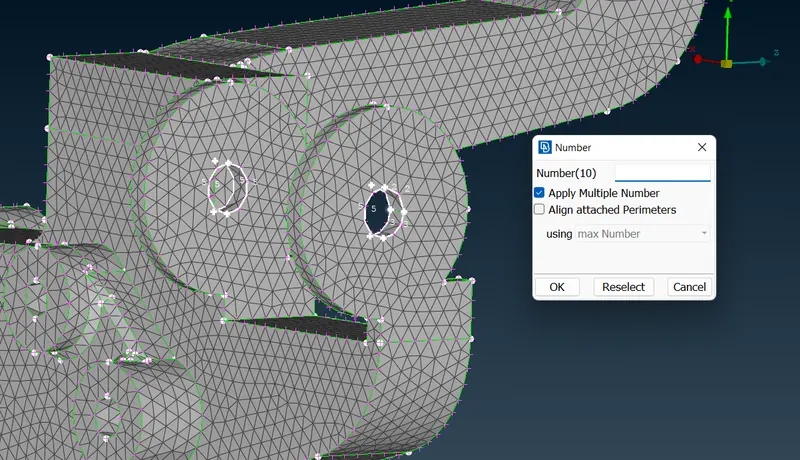
* We also take care of even numbers in hole perimeters.
* Surface Mesh Generation For Tyre And Rim:-(tria elements)
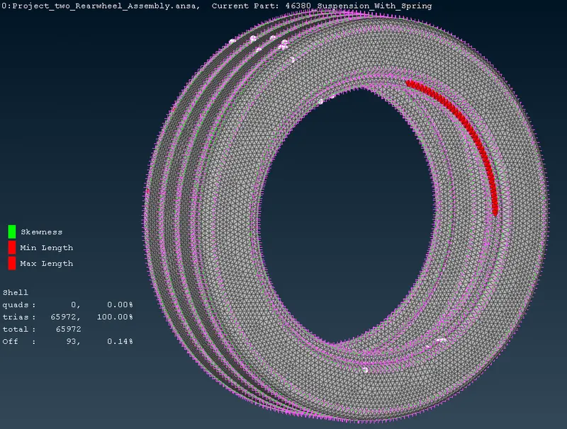
fig - after batch mesh
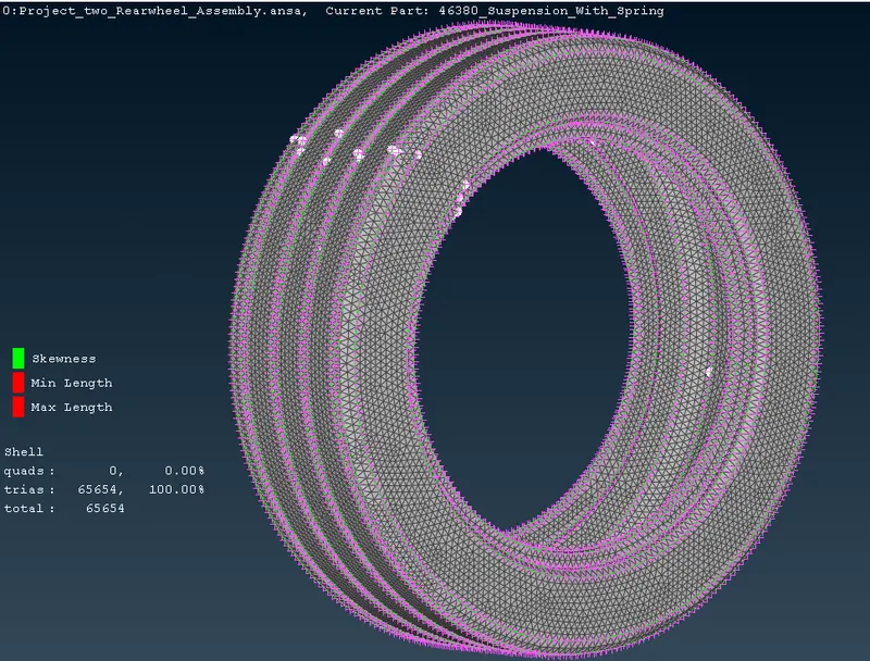
fig - after clearing quality
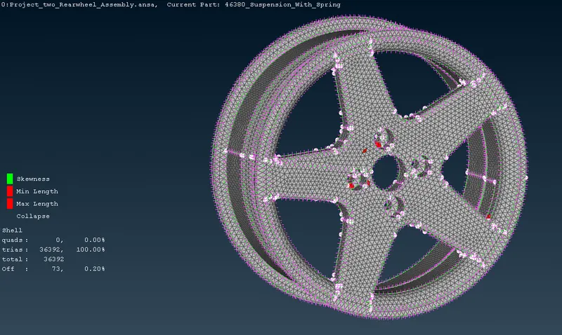
fig - after batch mesh
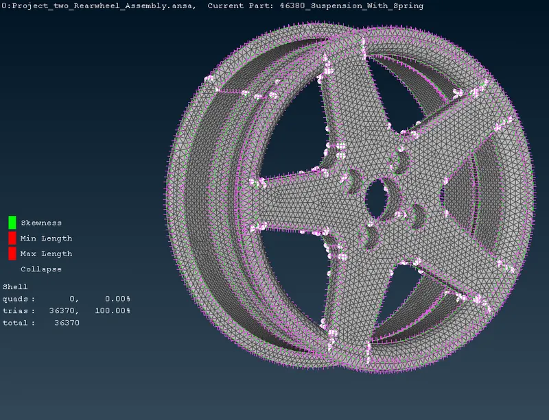
fig - after clearing quality
* Shell meshing of uniform thickness parts:-( mixed elements)
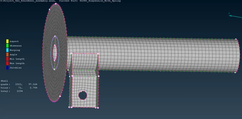
fig - after clearing quality
* Surface Mesh Generation For Non Uniform thickness components other than Tyre and Rim :-(tria elements)
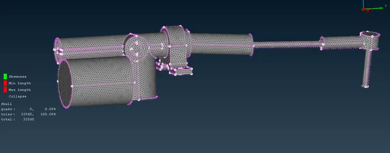
fig - after batch mesh and clearing quality
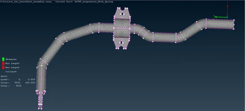
fig - after batch mesh and clearing quality
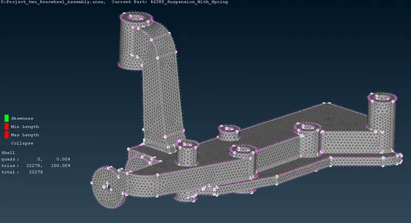
fig - after batch mesh and clearing quality
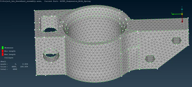
fig - after batch mesh and clearing quality
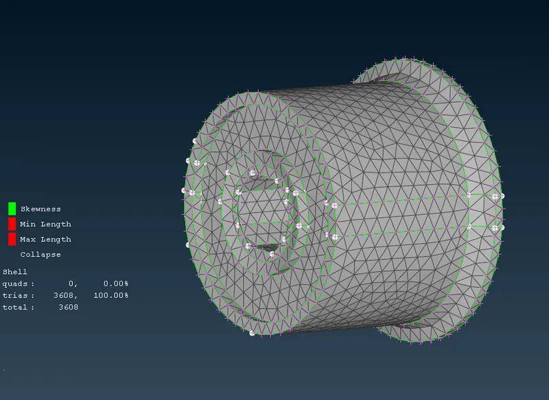
fig - after batch mesh and clearing quality
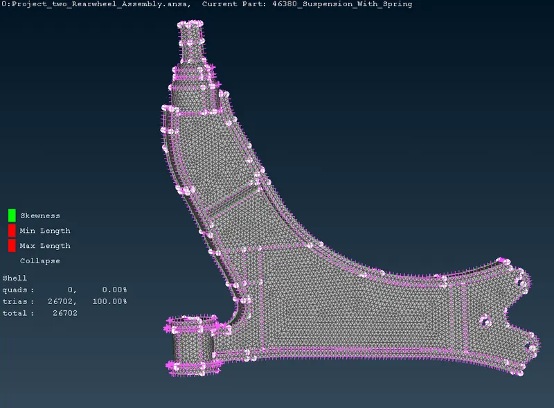
fig - after batch mesh and clearing quality
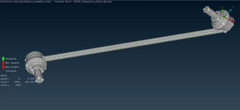
fig - after batch mesh and clearing quality
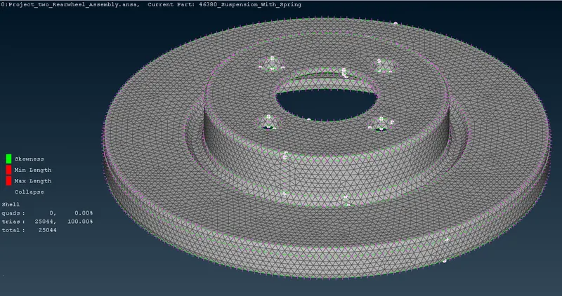
fig - after batch mesh and clearing quality
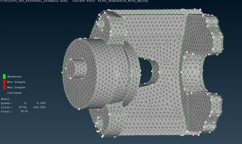
fig - after batch mesh and clearing quality
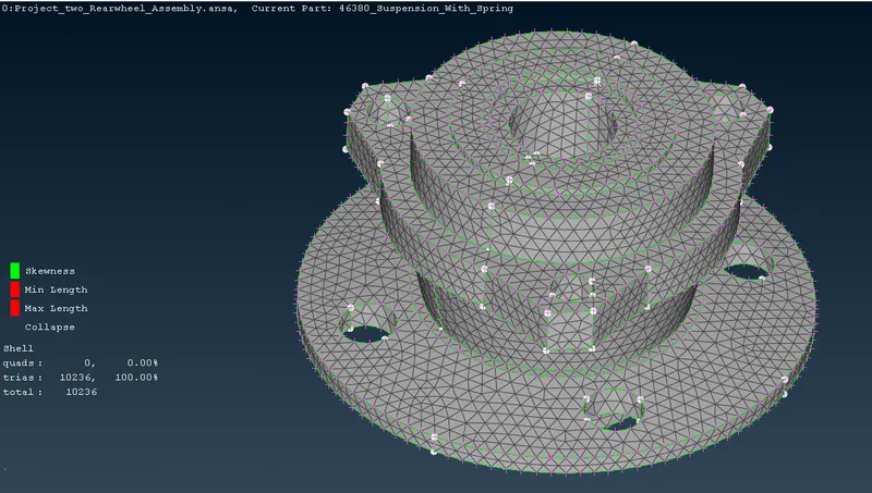
fig - after batch mesh and clearing quality
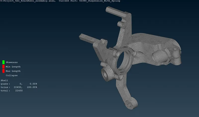
fig - after batch mesh and clearing quality
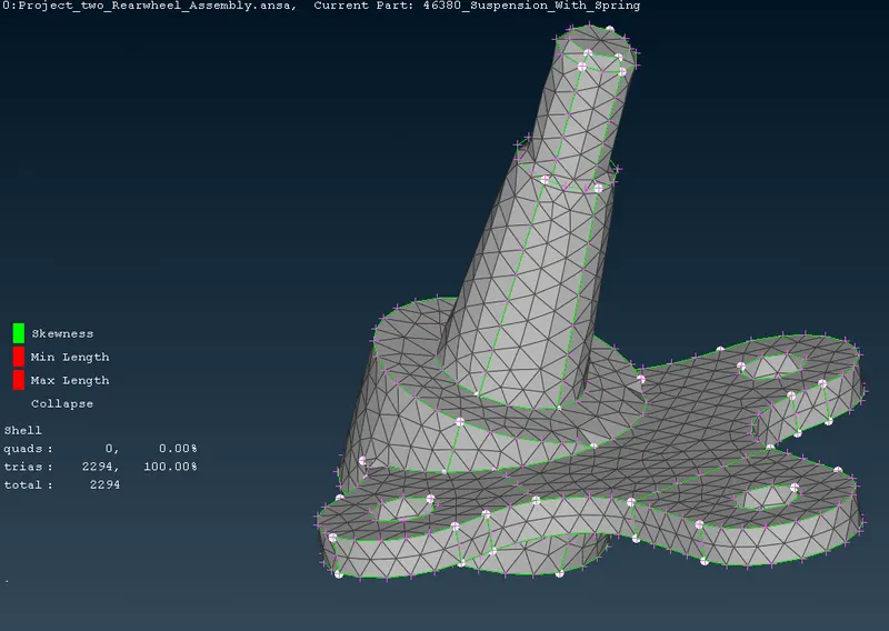
fig - after batch mesh and clearing quality
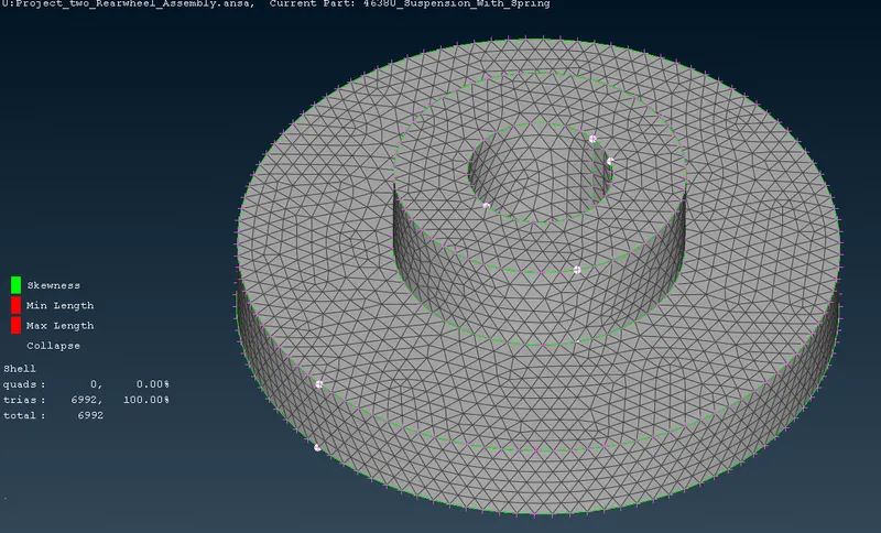
fig - after batch mesh and clearing quality
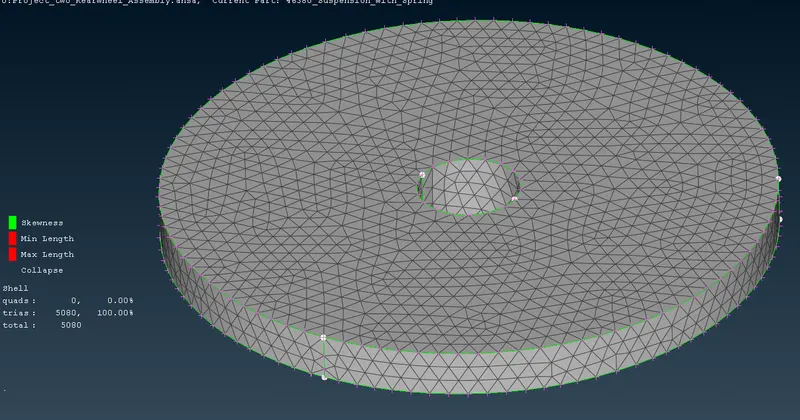
fig - after batch mesh and clearing quality
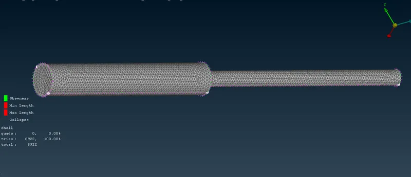
fig - after batch mesh and clearing quality
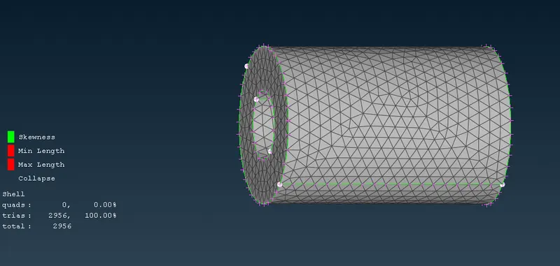
fig - after batch mesh and clearing quality
* 3D Meshing
* Solid Mesh Generation For Tyre And Rim And For Non Uniform thickness components other than Tyre and Rim
* After surface meshing on the components , the volume mesh is deployed on the components.
* For generating volume mesh first we have to create volume for the components.
* For define volume we go to volumes - define and click on Ok it will detected automatically volumes and also create solid property.
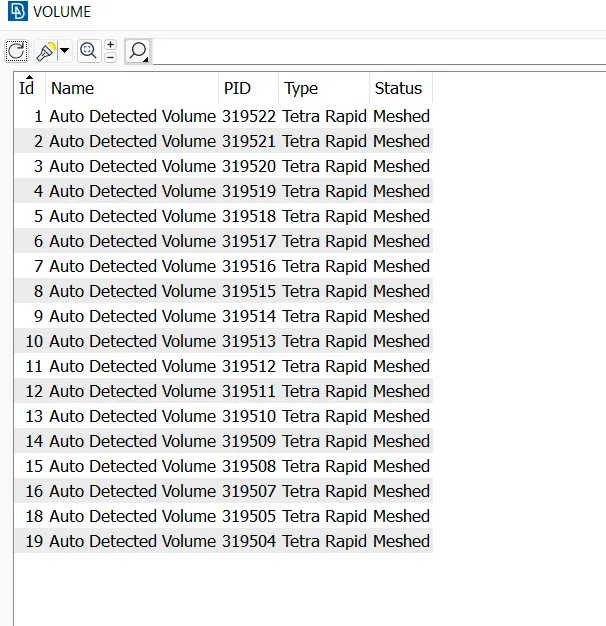
* In above image we can see that created volume for all 3d comoponents.
* After creating volume for the components we use tetra rapid method for generating solid mesh on the components.
* Next we need to check the solid elements to see if any fail for the tet collapse criteria by switching to hidden mode. There are two ways to fix tet collapse failures. One is by using the Fix Quality tool from the volume mesh module (Improve > Fix Quality). but in this way the surface element are get disturbed.
* Other method to solve the tet collapse failed element is move free the element in desired axis to clear the quality.
* In this way we do solid meshng for all component one by one.
Representation Of Solid Mesh With Clear Quality Criteria:-
- Tyre and Rim
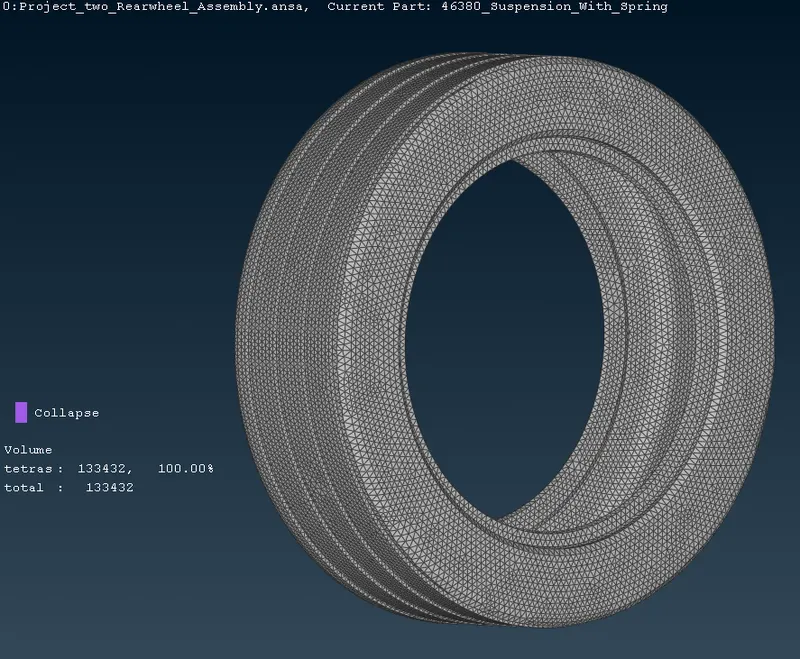
fig - Clear quality criteria
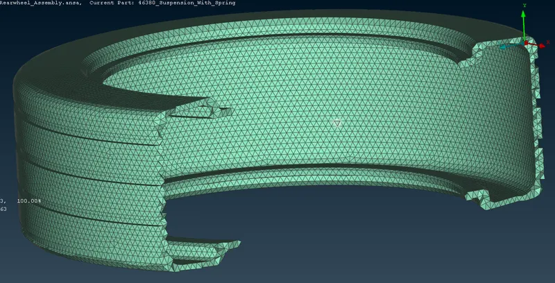
fig - Cross sectional view of solid mesh
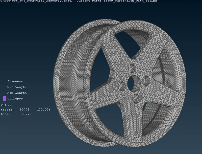
fig - Clear quality criteria
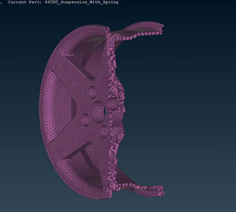
fig - Cross sectional view of solid mesh
- Solid Components other than tyre and rim
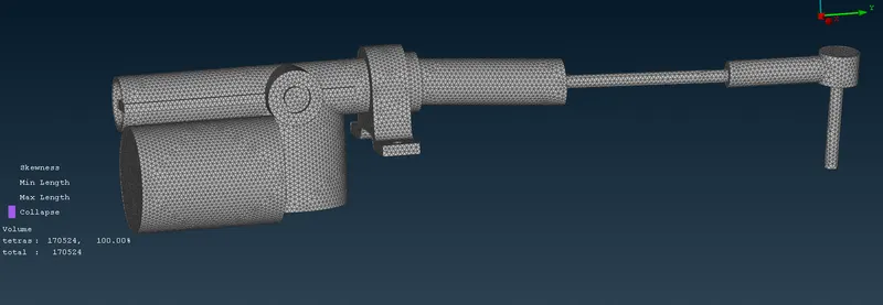
fig - Clear quality criteria
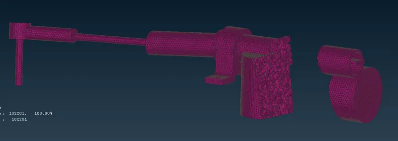
fig - Cross sectional view of solid mesh
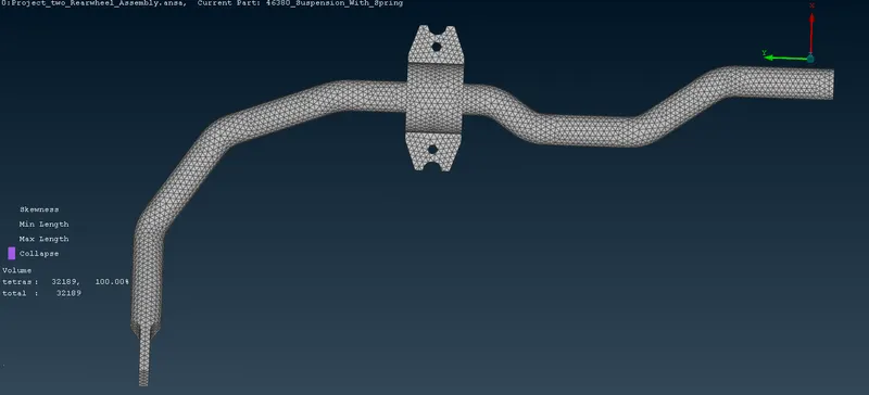
fig - Clear quality criteria
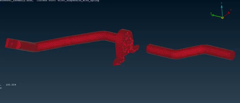
fig - Cross sectional view of solid mesh
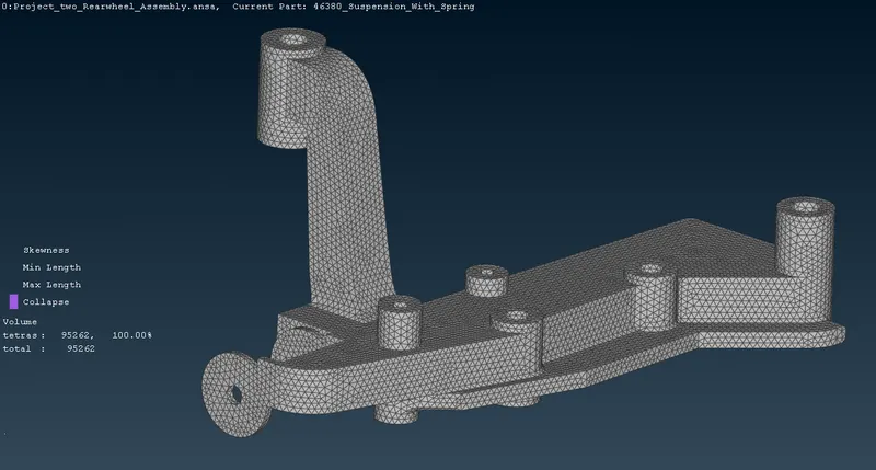
fig - Clear quality criteria
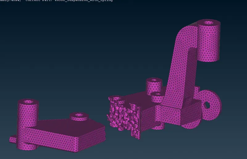
fig - Cross sectional view of solid mesh
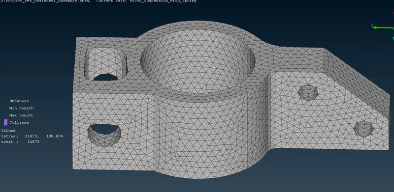
fig - Clear quality criteria
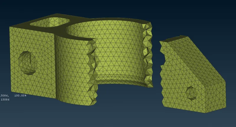
fig - Cross sectional view of solid mesh
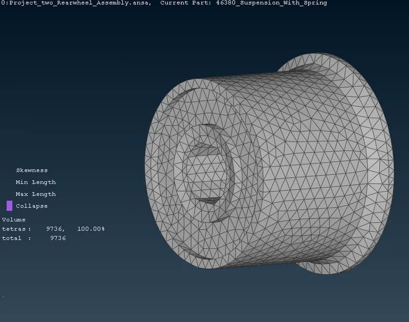
fig - Clear quality criteria
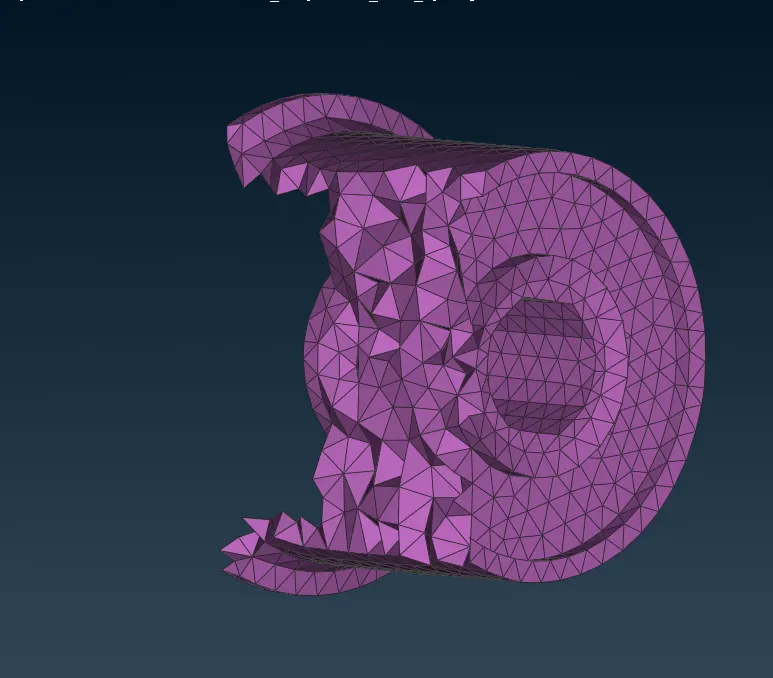
fig - Cross sectional view of solid mesh
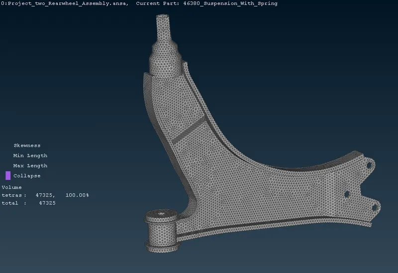
fig - Clear quality criteria
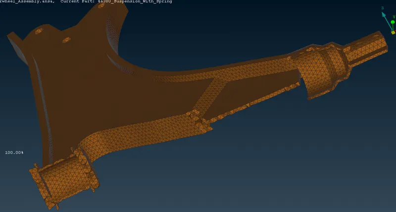
fig - Cross sectional view of solid mesh
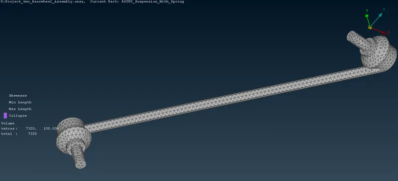
fig - Clear quality criteria
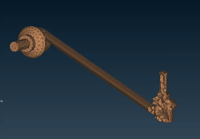
fig - Cross sectional view of solid mesh
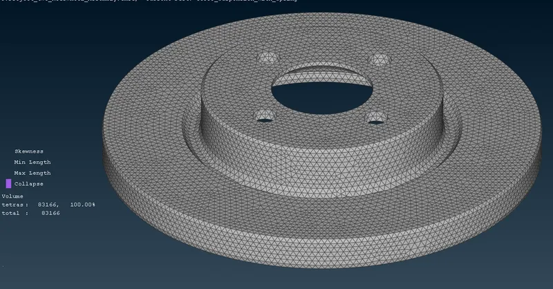
fig - Clear quality criteria
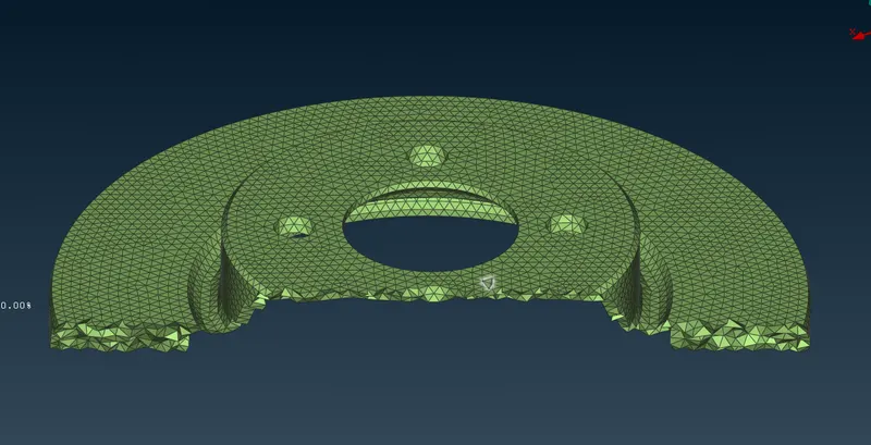
fig - Cross sectional view of solid mesh
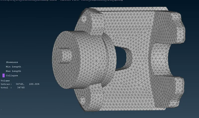
fig - Clear quality criteria
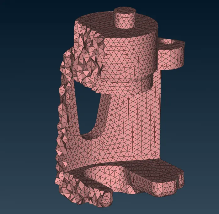
fig - Cross sectional view of solid mesh
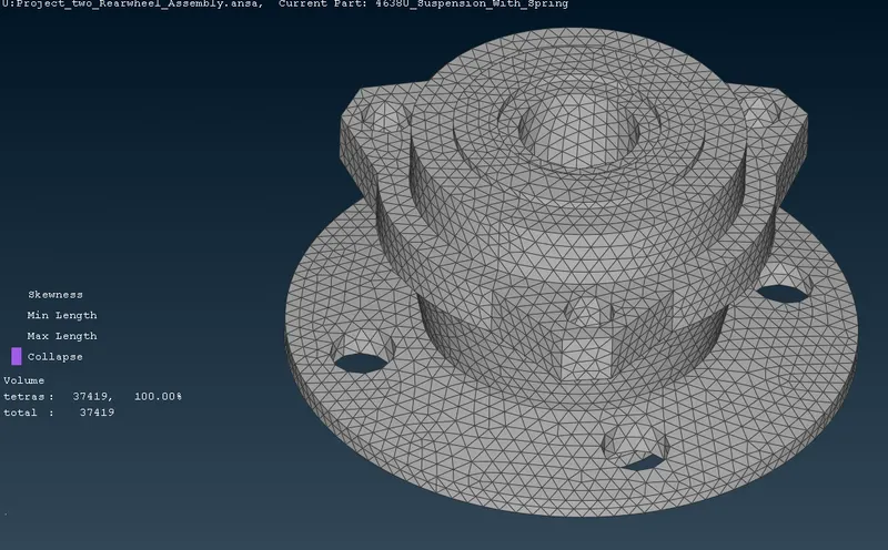
fig - Clear quality criteria
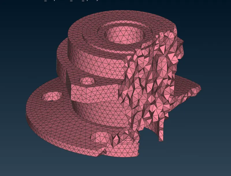
fig - Cross sectional view of solid mesh
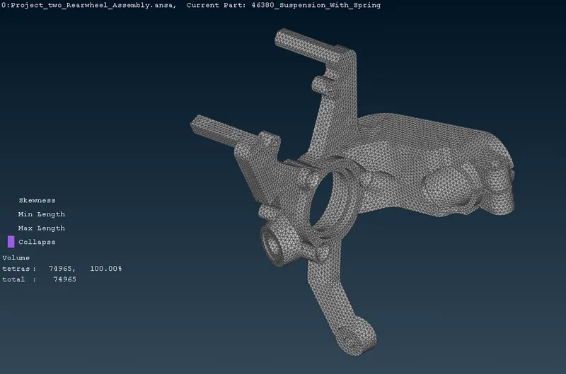
fig - Clear quality criteria
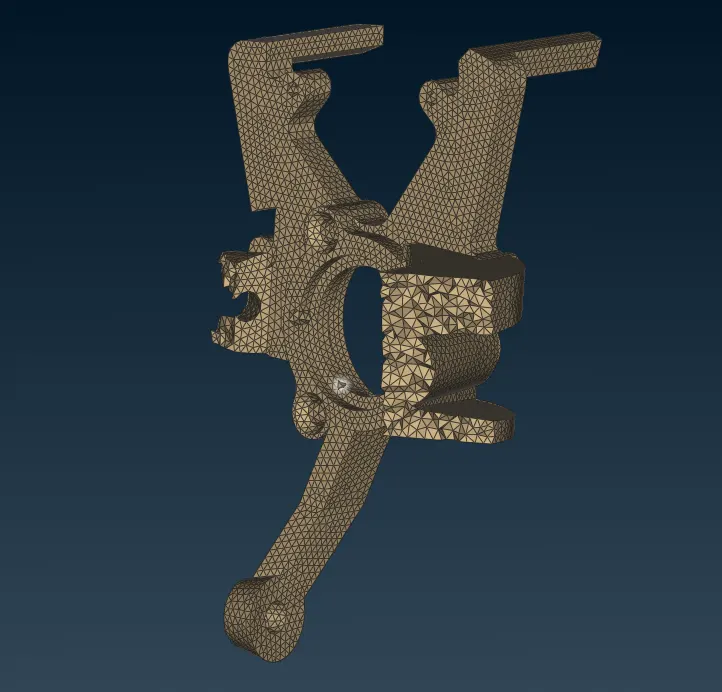
fig - Cross sectional view of solid mesh
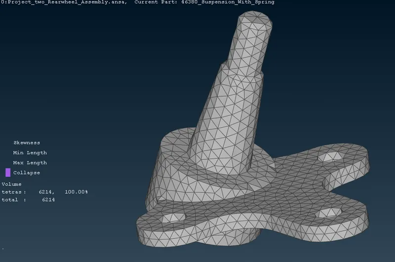
fig - Clear quality criteria
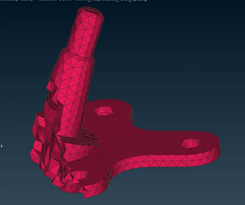
fig - Cross sectional view of solid mesh
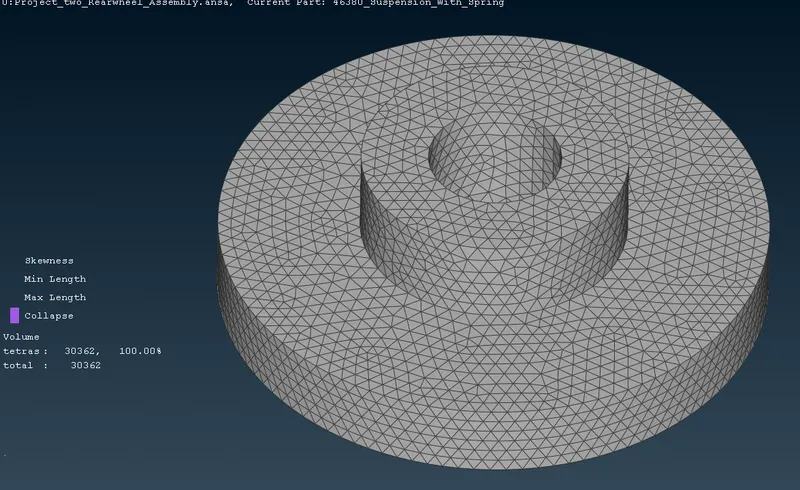
fig - Clear quality criteria
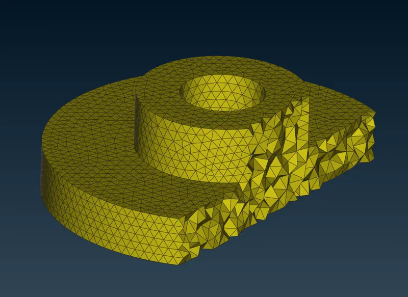
fig - Cross sectional view of solid mesh
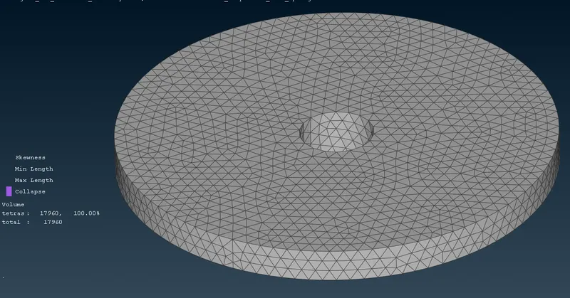
fig - Clear quality criteria
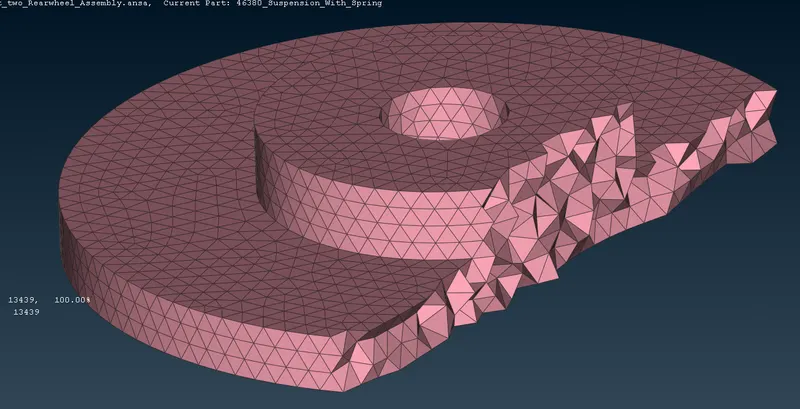
fig - Cross sectional view of solid mesh
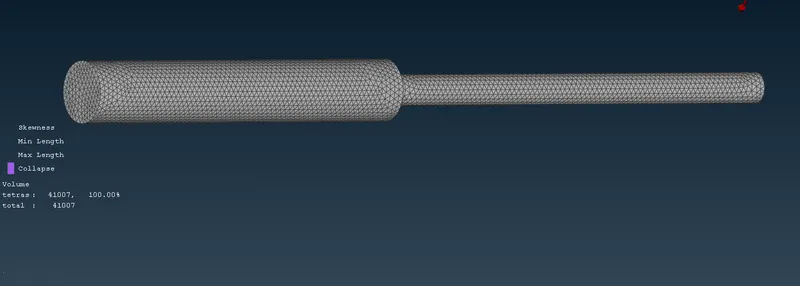
fig - Clear quality criteria
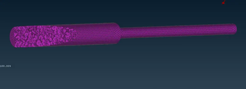
fig - Cross sectional view of solid mesh
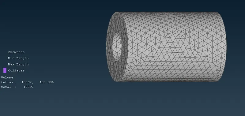
fig - Clear quality criteria
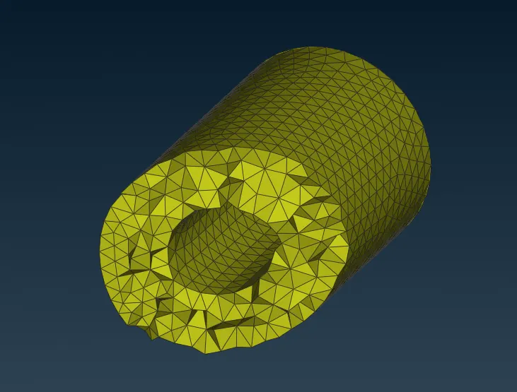
fig - Cross sectional view of solid mesh
6) Model of Suspension Spring:-
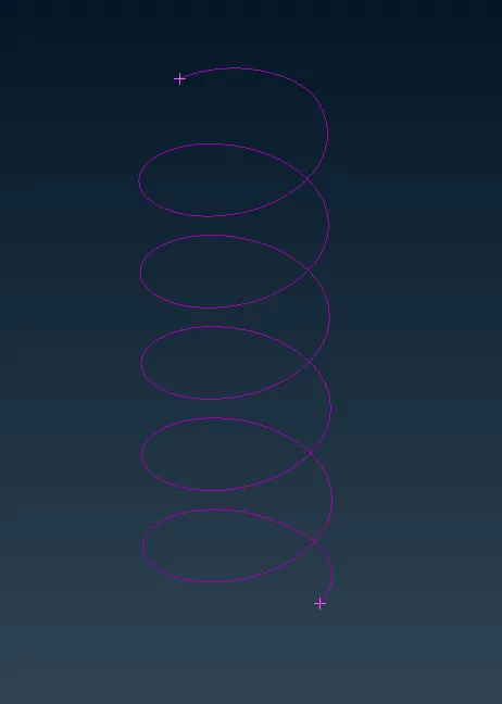
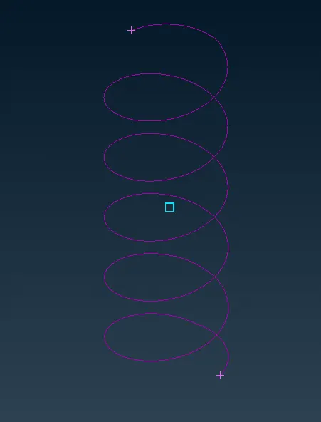
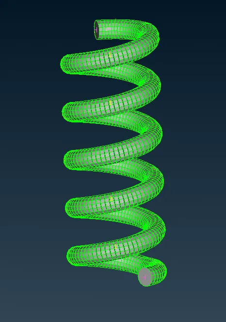
* For model the suspension spring as a CBAR element we create mid curve from suspension spring geometry by using middle curve tool. ( topo - curve - middle curve )
* After getting curve we create COG point on curve. ( topo - points - on COG )
* Then we go to NASTRAN deck and create CBAR element on curve by giving element length as 4 and redius value in property tab and create CBAR elements for suspension spring.
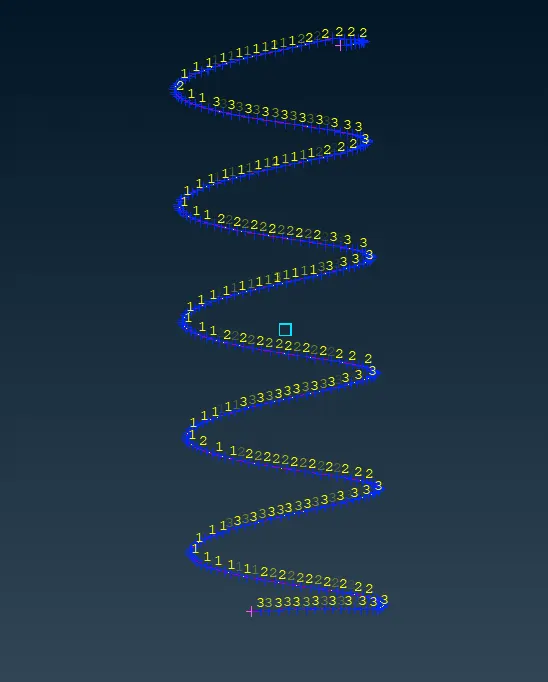
* We go to quality criteria tab and check the box ( line element cross section to see representation of 1D bar elements as solid.
7) CONNECTIONS :-
* After completion of meshing of whole model with given instructions we must connect them by using connections like bolts , spot weld , seam weld , RBE2 cluster and two node RBE2 element.
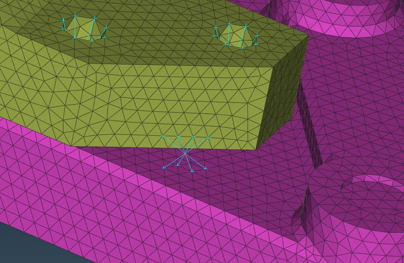
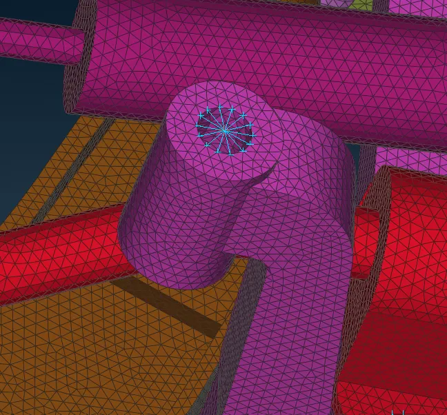
1) RBE2 cluster and two node RBE2 element connection:-
* For this type of connection we go to NASTRAN deck and use RBE2 element. ( NSATRAN deck - elements - RBE2 )
* We use this connection in hole where other part has to be connect and where we can not deploy weld or bolt connection we use RBE2 rigid connection.
2) Bolt Connection:-
* In this model we connect two parts by using bolt connection.
* For creating bolt we use RBE2 elements.
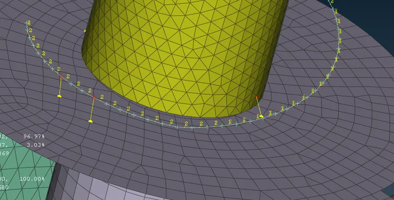
* we create RBE2 cluster on holes of both part and in between master node of cluster we create two node RBE2 element as a bolt body.
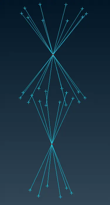
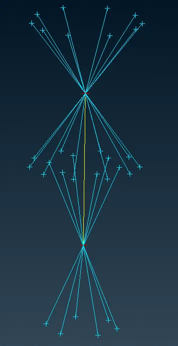
* In above image we can see the process of creation of bolt.
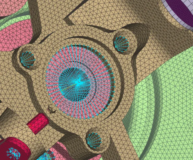
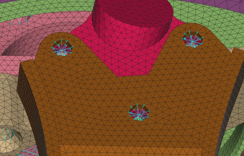
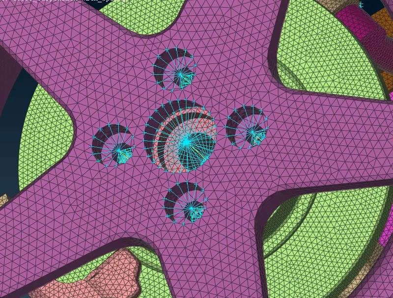
* In above image we can see that the bolt connections.
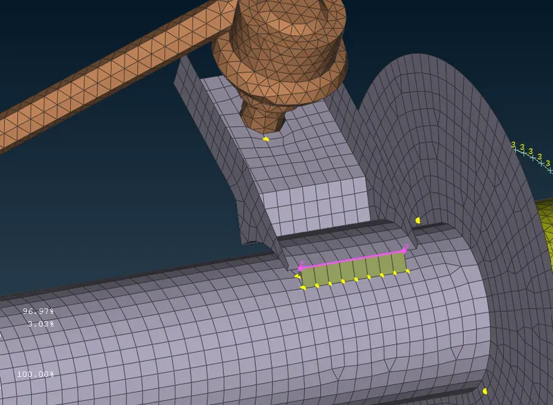
3) Seam weld connection:-
* In this model we use overlap shell joint seam weld for connecting two parallel parts.
* In given model there is no data given for welds so we have to generate the weld data from FE model.
* For generating the weld data we create curves from FE model. ( Mesh deck - Perimeters - Feat2Curve ).
* Then we convert this curve to seam line by convert tool. ( Assembly - convert - curves - seam line )
* After the conversion of curve we proceed to create seam weld , for this we go to connectin manager and select this created seam line and open connection manager after this we select parts and then select the FE rep type as OVERLAP-SHELL ( Because our parts are palallel to each other ). The root shell option would be 'double row'. Other properties (such as width or thickness) and PID can be assigned for the weld as well if needed.
* We created the property for seam weld by clicking shift+/ in weld PID box and create the property.
* Representation of seam weld is shown in below image.
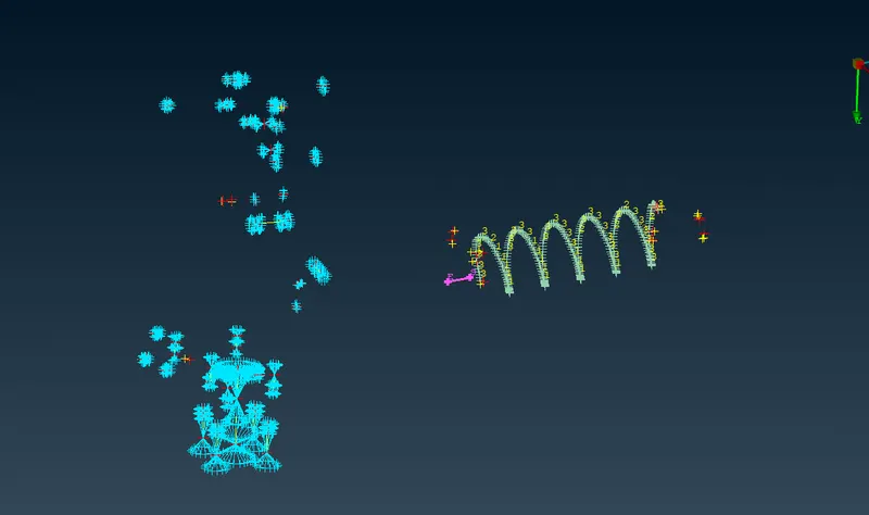
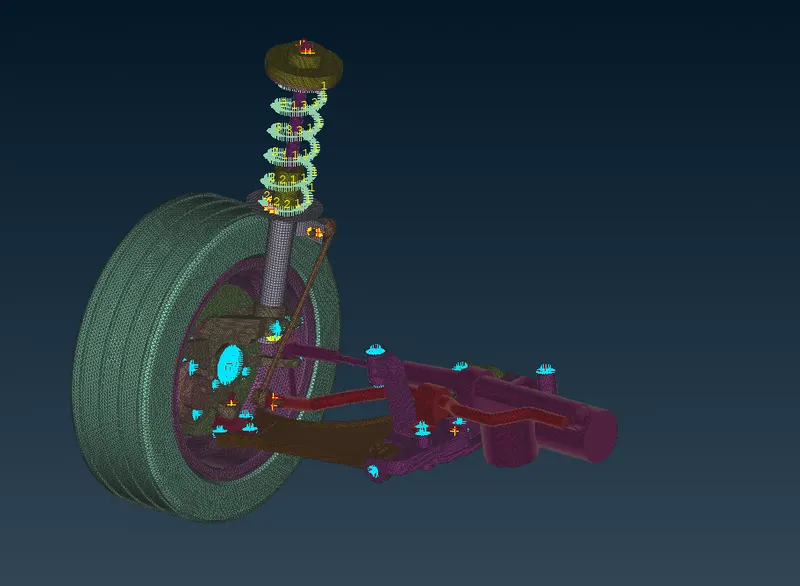
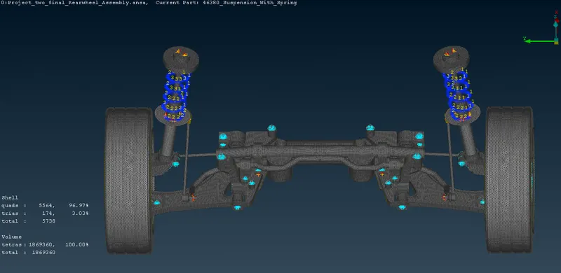
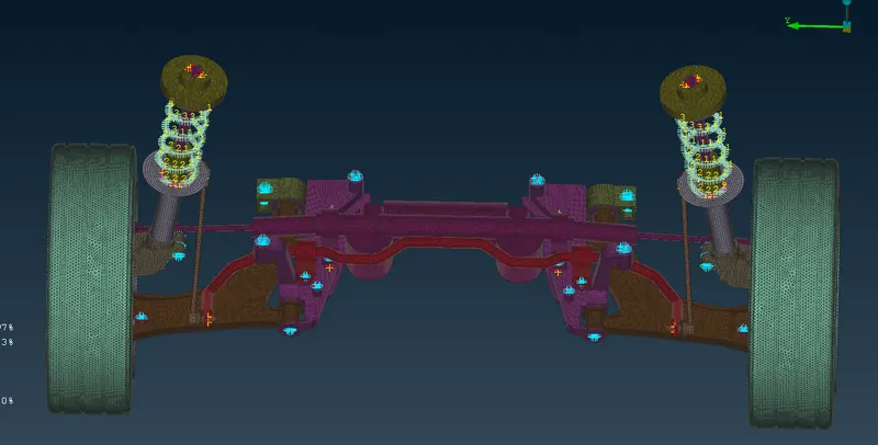
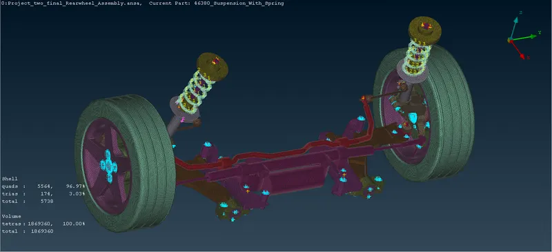
* Below image shows the all connection in model.
8) Symmetry Process:-
* Before do symmetry process we have to release the 2D and 3D elements.
* Then we go to transform tool and clik on copy the entites and select symmetry option and use 3 point symmetry option and refelect the model.
Learning Outcomes:-
* Understood geometry cleanup.
* Understood 2D and 3D meshing.
* Learned how to give connections.
Conclusion:-
In this project , i meshed the suspension assembly with 2D as well as 3D elements as per given quality criteria and instructions and create connections to connect various parts in model.