Project - 2 - Meshing on the suspension Assembly
Project-2
Meshing on Suspension Assembly
The ANSA file has been uploaded on google drive and the access link to the file is
https://drive.google.com/file/d/1Ht09MebI2yME7pnBMpX-p7HCa9UDQWZ8/view?usp=sharing
Aim:
To check for geometrical errors and obtain clean topology for the rear suspension model. To identify shell and solid components and mesh them with appropriate meshing techniques and consider the quality criteria. To give the connections between various components and mirror the model symmetrically to obtain the whole rear suspension assembly.
Quality criteria:
For Tyre and Rim:
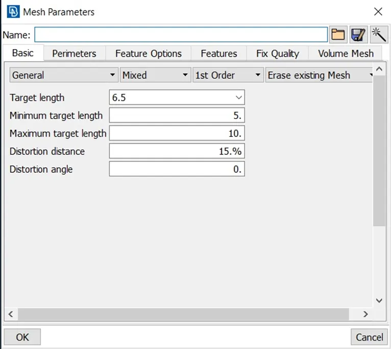
Average length :6.5
Min Length :5
Max Length :10
Skewness :45
For Non-uniform thickness entities:
Average length :4
Min Length :2
Max Length :6
Skewness :45
For Uniform Thickness entities:
Average length :4
Min Length :2
Max Length :6
Aspect :3
Warpage :15
Skewness :45
Jacobian :0.7
Minimum Quad Angle :45
Maximum Quad Angle :135
Minimum Tria Angle :30
Maximum Tria Angle :120
For Vol mesh
Tetra Collapse :0.2
Procedure:
Initially, we have to import the given 3D model into the ANSA workspace. Then we have to do the geometrical check on the imported model, and need the fix the errors which exist while checking the model bye automatically and manually.
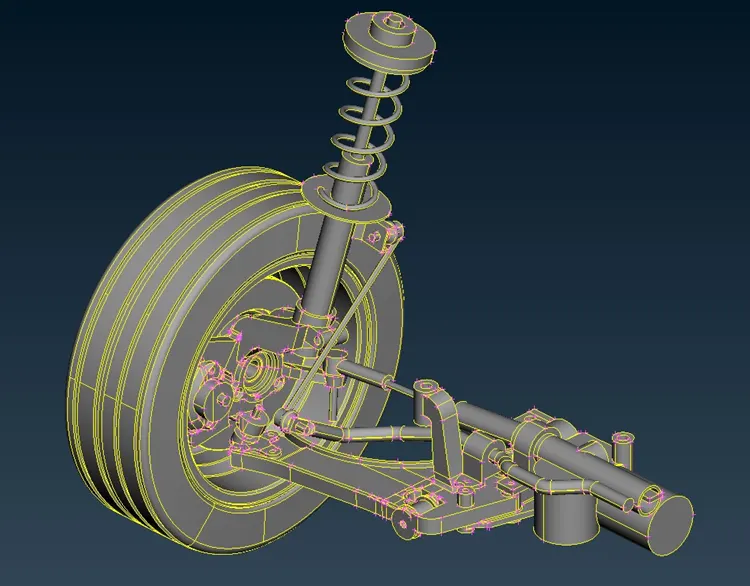
The above images show the imported 3D model.
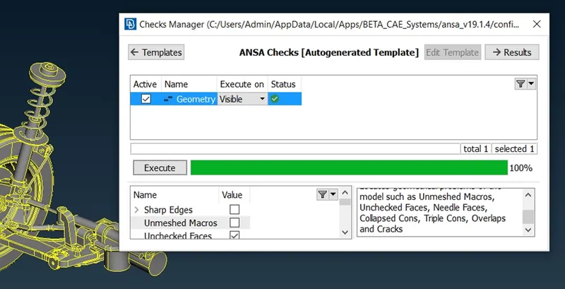
After cleaning geometrical errors, different PIDs have to be set for different parts of the system, using the “Set PID” option available under the face tab in the TOPO module.
After assigning different PIDs the model will be,
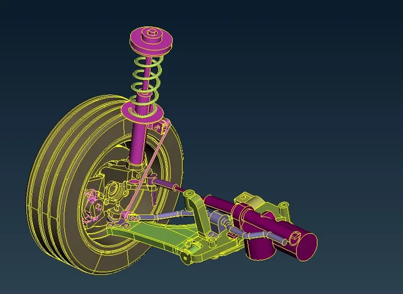
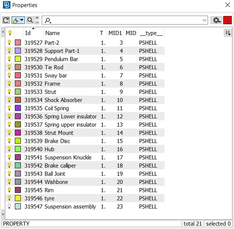
Meshing the tyre:
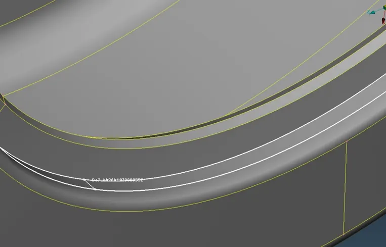
At first, we have to measure the length of the con in the tyre to achieve min and max length criteria.
Then we have to give the input for mesh parameters as given,
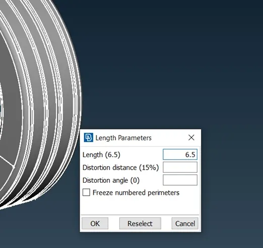
Then go to mesh module, apply length parameters as 6.5, which is average length in this case
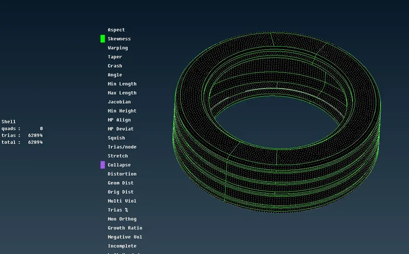
Then we have to mesh the surface using the spot mesh option available in the mesh tab. Mesh elements have to be maintained as ortho tria for curved surfaces and Tria for the flat surface. After finishing the meshing, apply the quality criteria which were given, and switch to hidden mode to find the off elements, the off elements are eliminated using reconstruction, reshape, smooth, improve, split, join, and swap options available in the mesh module.
The switch to volume module and define the volume and then we have to mesh the volume which we have defined as,
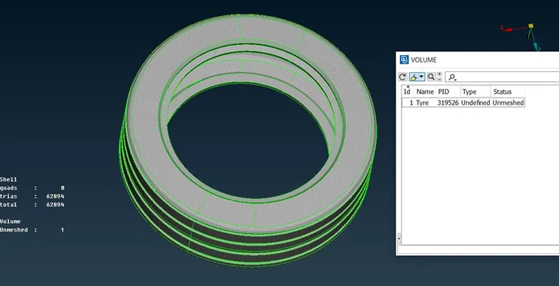
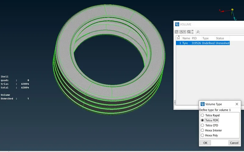
Meshed volume will be
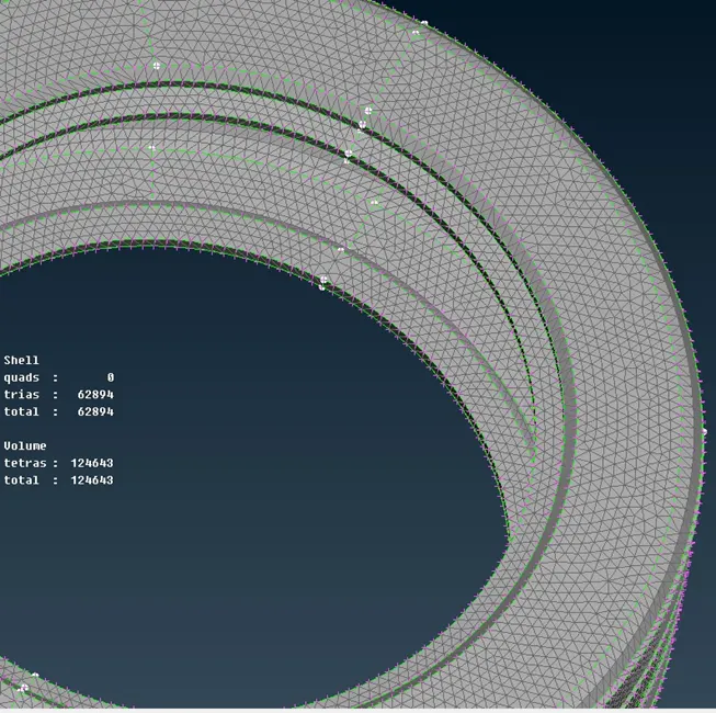
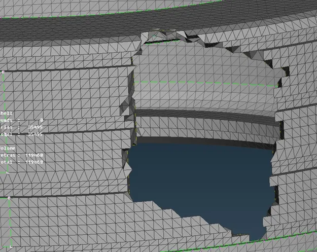
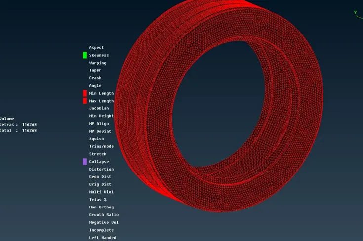
Likewise, we have to mesh all parts of the system according to the mesh parameters given and then we have to define the volume for each part.
For Rim;
Check for min and max length and we have to alter the length of the part.
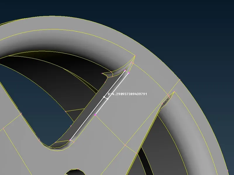
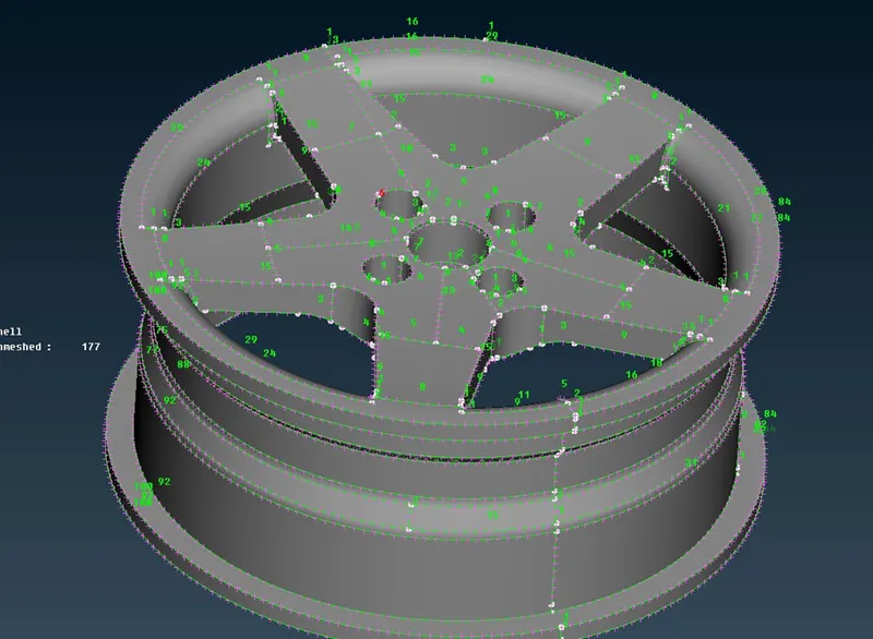
The mesh parameters are
Then off elements are removed,
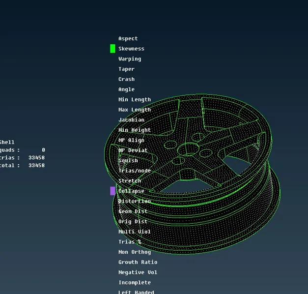
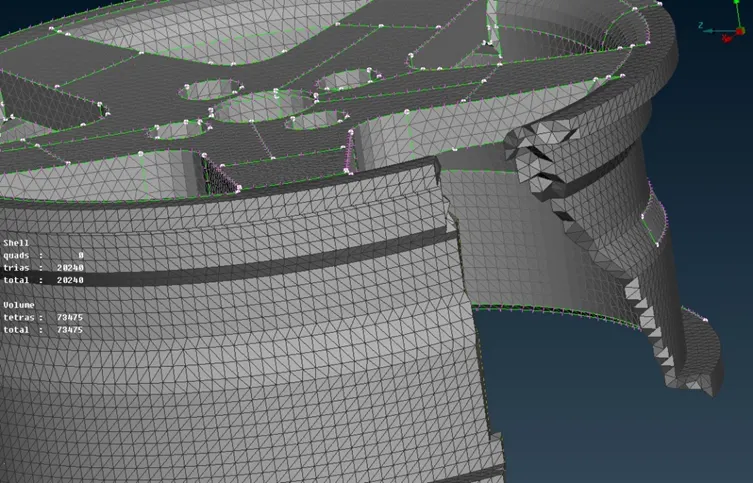
All other non-uniform parts have been meshed and defined in volume.
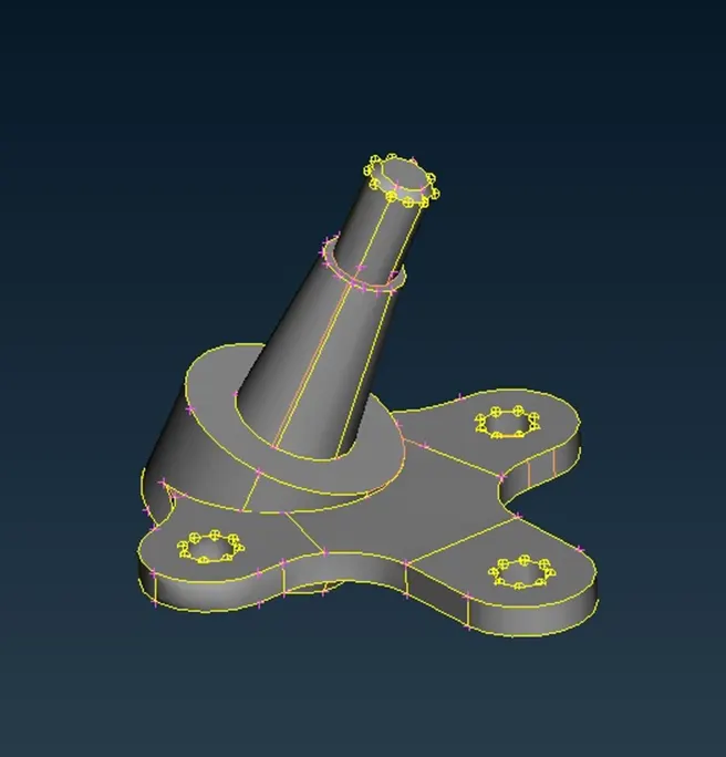
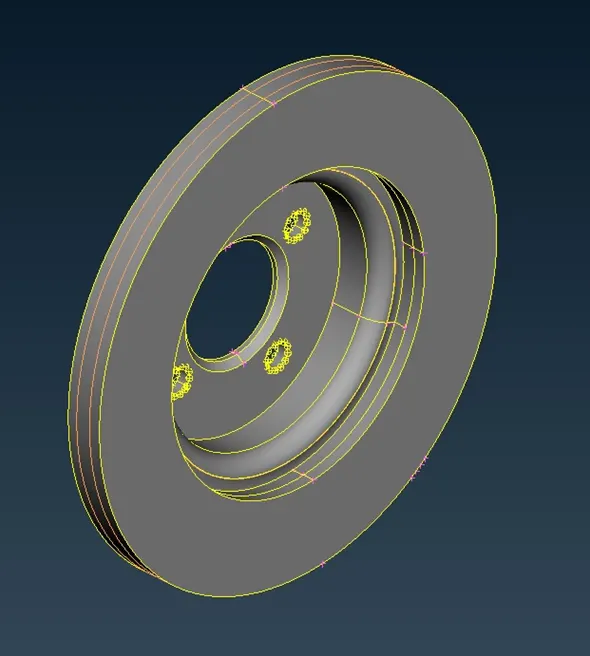
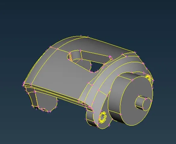
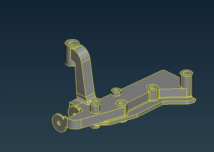
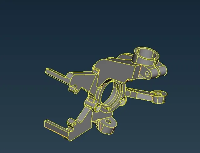
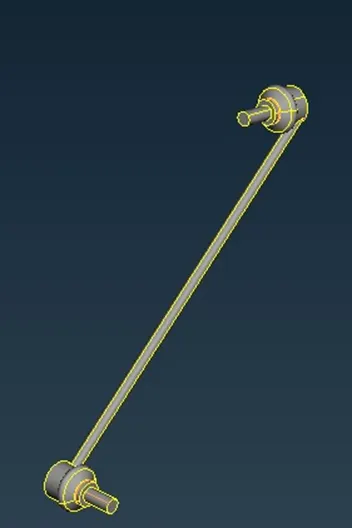
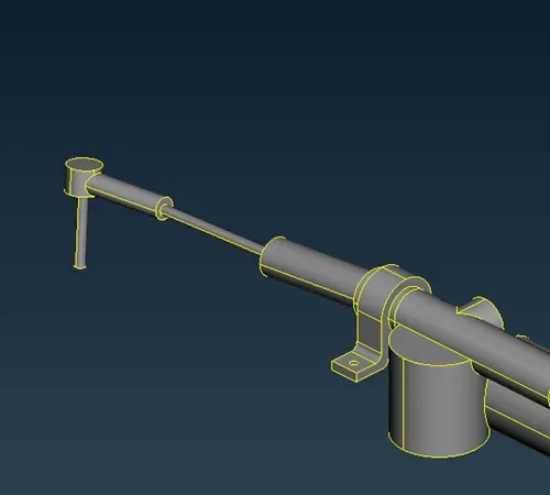
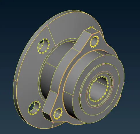
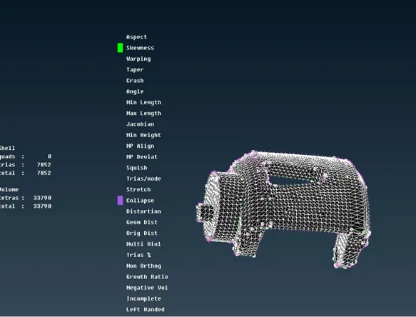
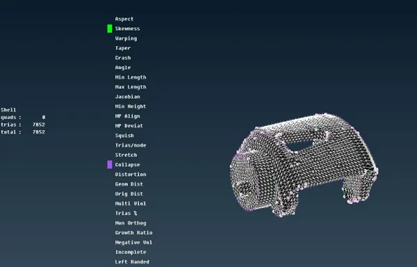
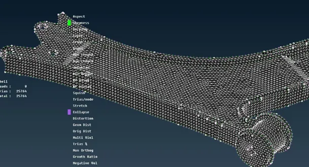
the parts are meshed and off elements are removed as mentioned above. Some of the volume meshed parts are
1 D meshing of spring element:
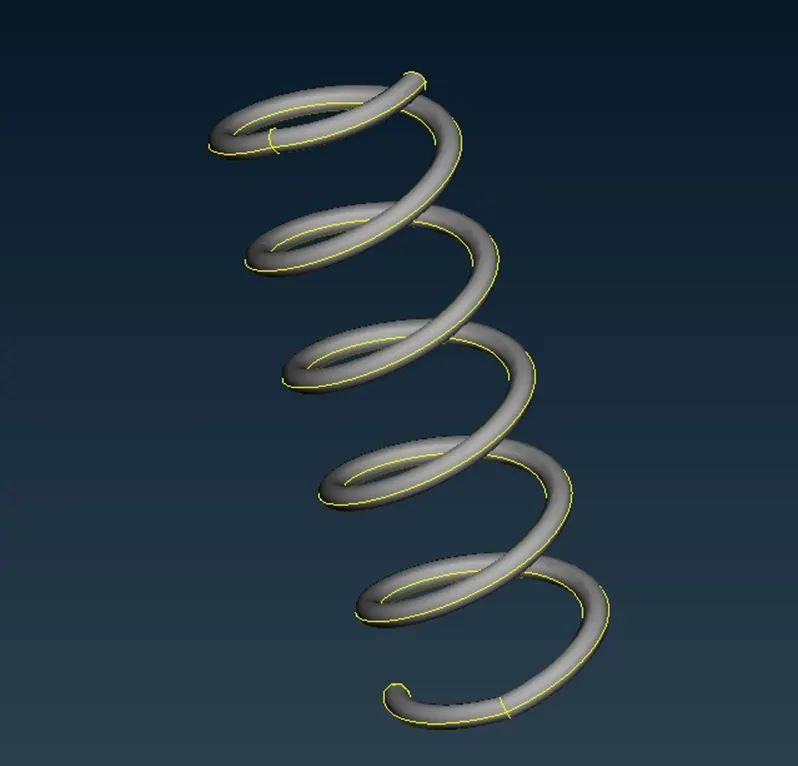
The above image shows the coil spring of the suspension assembly. The coil diameter is measured as 10mm. one-dimensional representation of the spring can be achieved using the “middle option” in the curve tabs under Topo module.
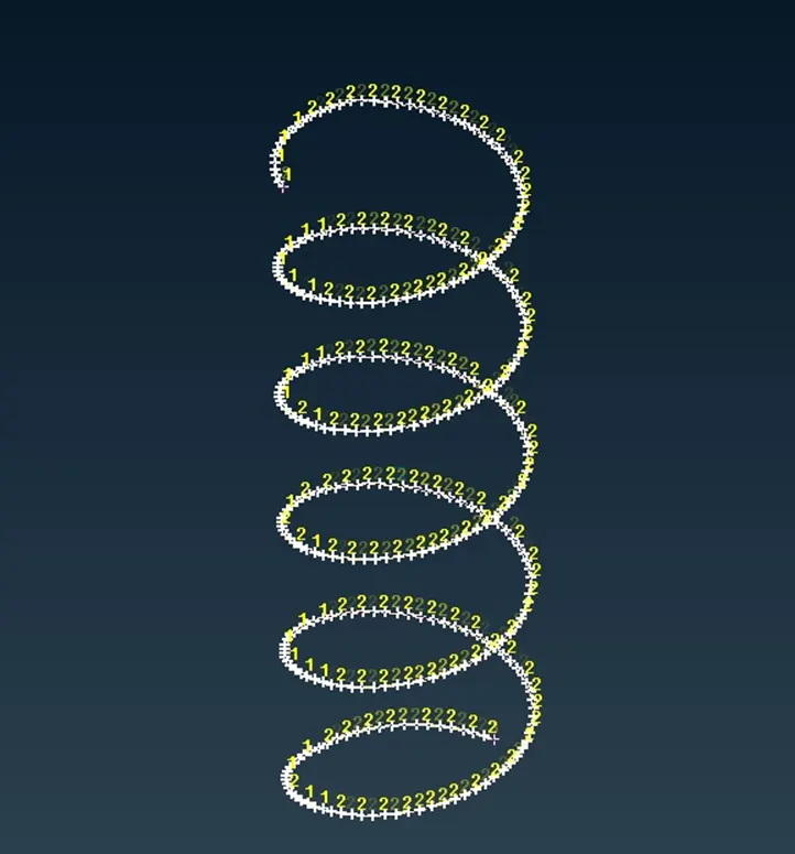
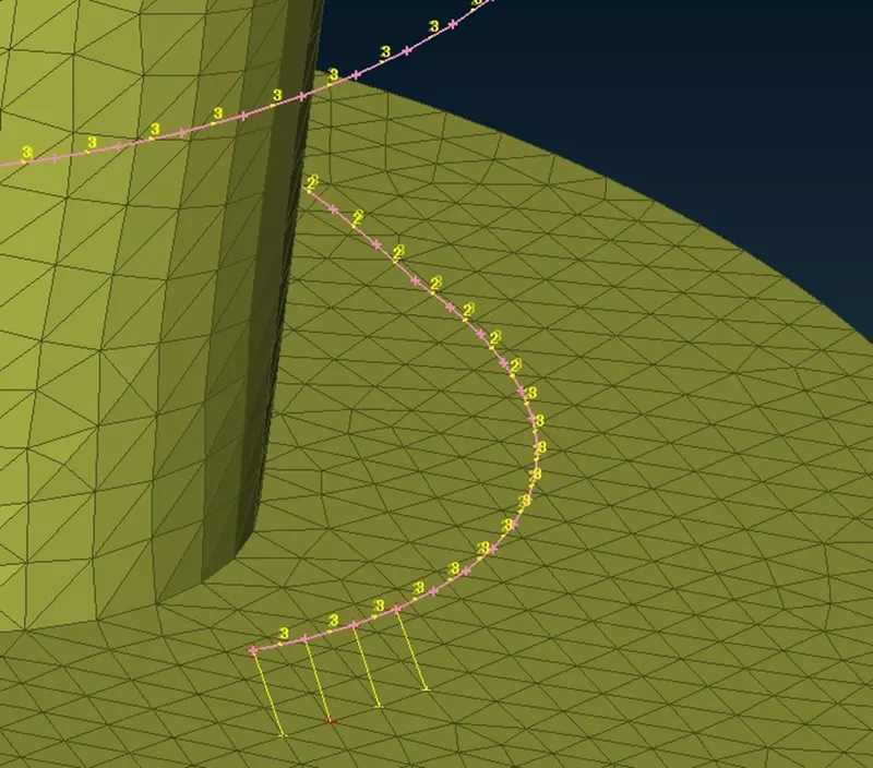
Then the created curves are connected using Curve > Connect opton. Then a 3D point is created using Topo > Point > On COG and select the curve.
Then go to Nastran module > elements > CBAR function. Select the curve and proceed, give length as 4mm.
And in property card for area(A), give R the value of radius of the spring.
Thus the spring will be
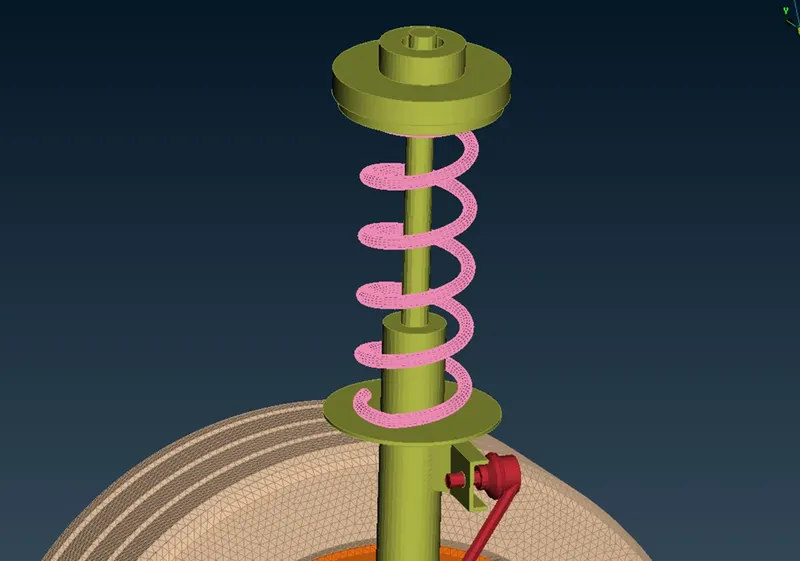
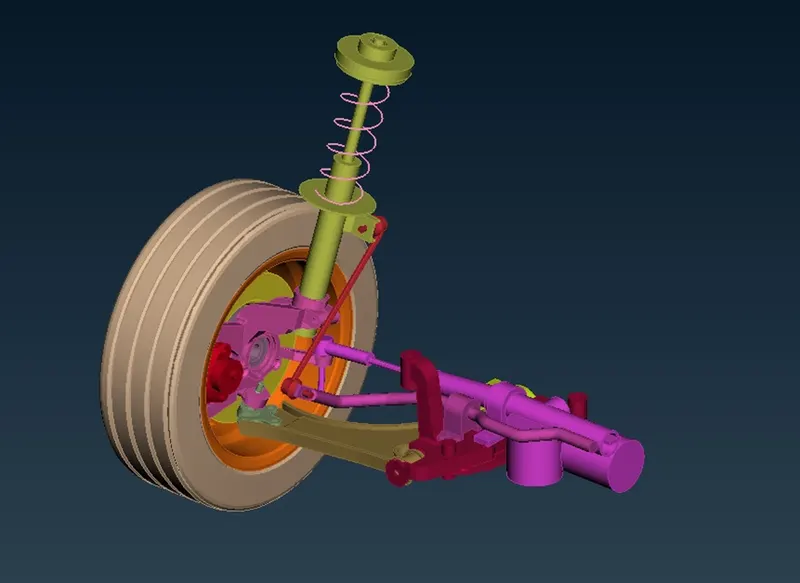
When checked line element cross-section as solid in quality criteria, it will be developed as
Assigning connections between the parts;
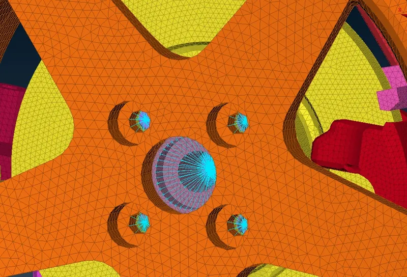
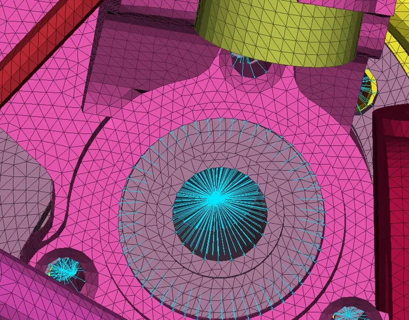
Various parts are connected using various connections such as RBE2, seam weld, and bolted connection and some of them are shown below.
To assign a rigid connection between two parts, RBE2 is used.
And also in some connections, certain parts have to rotate at a certain angle, so to release the part in the particular axis, figure out the axis and have to left out while giving degree of freedom while engaging the connection using RBE2.
Mirroring the suspension system;
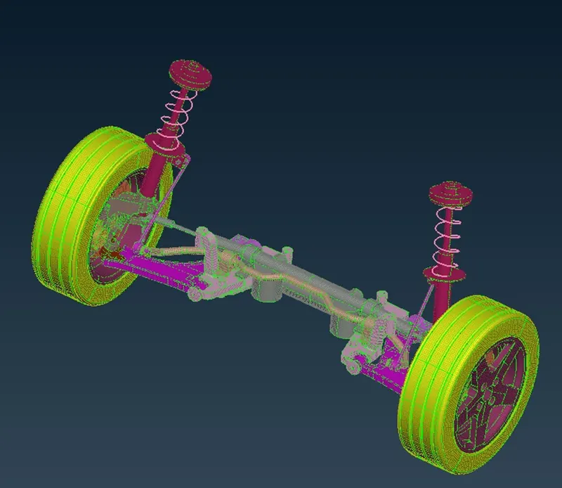
Go to transform under utilities and then the symmetry tab is selected with Mirror 3 points plane. Then select 3 nodes in the part and then proceed and the result will be
Learning outcomes:
Learning about geometry cleanup, and assigning different PID for each part,.
Meshing the part surface, eliminating off elements using different methods, to achieve quality criteria.
Defining the 3D volume of the meshed parts and 3D meshing the volume using the Tetra FEM method.
Creating connections and CBAR elements between the parts created.
Conclusions:
the given model had checked for geometrical errors, and then different parts of the component is assigned with different PIDs. Each part has meshed individually for the mesh parameters which was given and then components of the suspension system are defined in volume form and then meshed. And finally, connections have been assigned to the parts which are meshed.