Project - 2 - Meshing on the suspension Assembly
Aim: For the given assembly, check for the geometrical errors and mesh with the given element Quality criteria. After meshing the component the thickness has to be assigned for mid surfaces. Use tetra elements to model non-uniform thickness components.
Common Note:
- Use Volume mesh for Tyre and Rim with the below Quality criteria. (Use Tria Element)
- Use mid surface only when the thickness is uniform and less than 5 mm. (Use Mixed elements)
Quality Criteria for Surface Meshing of Tyre and Rim (Element type: Tria) :
|
S.No |
Quality Criteria |
Value |
|
1 |
Target/Average length |
6.5 |
|
2 |
Minimum Length |
5 |
|
3 |
Maximum Length |
10 |
|
4 |
Skewness |
45 |
Quality criteria for Surface Meshing of Non-Uniform thickness components other than Tyre and Rim (Element type: Tria) :
|
S.No |
Quality Criteria |
Value |
|
1 |
Target/Average length |
4 |
|
2 |
Minimum Length |
2 |
|
3 |
Maximum Length |
6 |
|
4 |
Skewness |
45 |
Quality Criteria for Volume meshing of all Non-Uniform thickness components (Element type: Tetra Elements):
|
S.No |
Quality Criteria |
Value |
|
1 |
Tet-collapse |
0.2 |
Quality criteria for Mid surfacing of Uniform thickness part which has a thickness less than 5 mm (Element type: Mixed elements) :
|
S.No |
Quality Criteria |
Value |
|
1 |
Target/Average length |
4 |
|
2 |
Minimum Length |
2 |
|
3 |
Maximum Length |
6 |
|
4 |
Aspect |
3 |
|
5 |
Warpage |
15 |
|
6 |
Skewness |
45 |
|
7 |
Jacobian |
0.7 |
|
8 |
Minimum Quad Angle |
45 |
|
9 |
Maximum Quad Angle |
135 |
|
10 |
Minimum Tria Angle |
30 |
|
11 |
Maximum Tria Angle |
120 |
Principle:
A car suspension connects your car body to the wheels through a network of shock absorbers and linkages. Whether you’re cruising down a bumpy dirt trail or just have a habit of hitting potholes, your suspension system works to maintain a smooth ride.
The main purpose of the suspension system is to optimize the performance of your vehicle while driving. The cabin of your vehicle sits on top of the suspension, which protects you from feeling every dip and bump of the uneven road below.
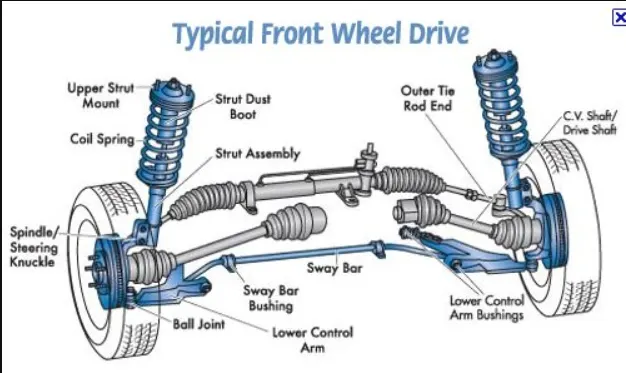
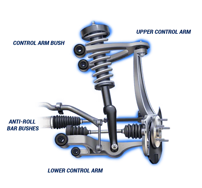
Main components of car suspension
-
Springs help control the height and load of the suspension and cabin
-
Shocks/dampers absorb the energy from terrain and dissipate it
-
Rods/linkages connect multiple parts of the suspension system
-
Joints/bearings/bushings allow sliding motion between certain parts of the system
-
The anti-sway bar stabilizes the direction of your car while moving
Types of suspension systems
-
Independent suspension: your back and front wheels move independently of one another.
-
Dependent suspension: the wheel direction is bound by axle movement. Essentially, there is a solid bar under the front of the car. This is common in trucks but not in cars.
Procedure :
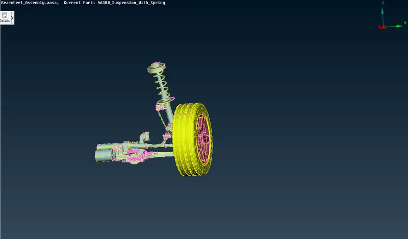
Import the model into the Ansa Software
 ]
]
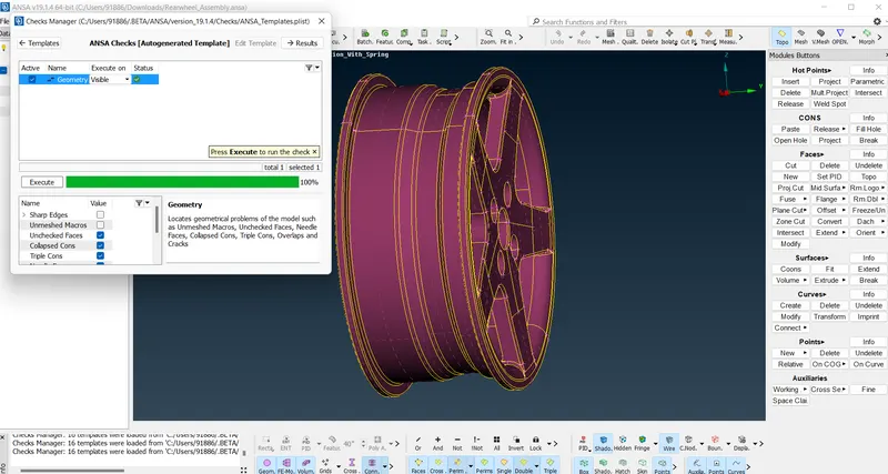
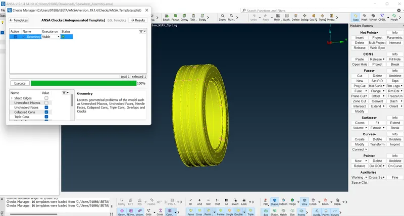
Perform TOPO on the model and check for geometrical errors
It's better to check the parts individually for geometrical errors as it is much easier to solve them
Geometrical errors can be solved manually or auto-fix option. Some errors cannot be fixed using the auto-fix option. It has to be rectified manually
(Rim)
(Tyre)
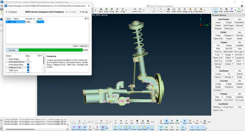
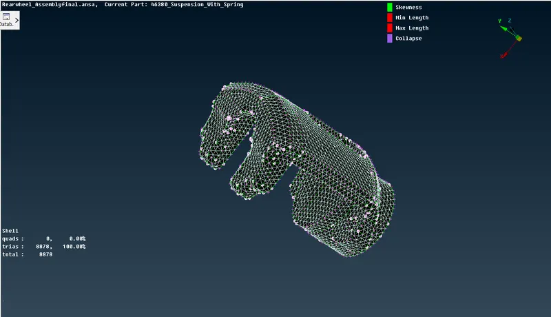
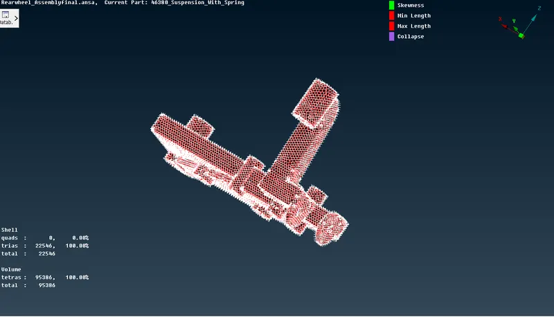
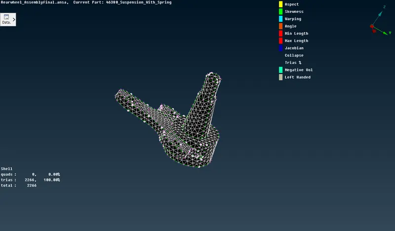
(Suspension system)
As seen from the above images the parts are checked individually for geometrical errors and rectified
After the system is free from geometrical errors. Mid-surface and Meshing can be done
As per the given Quality criteria, different meshing has to be done for parts with different thickness
for example, the tyre and rim have had to be done with volume meshing for the components having a thickness greater than 5mm (element type: Trias)
For components with thickness less than 5 mm mid surface and meshing has to be done (element type: Quads and trias)
For Tyre and rim :
Since tyre and rim do not have a specific thickness, Volume meshing is done
Before volume meshing cab be done required quality criteria have to be given
Quality criteria:
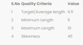
After entering the quality criteria, Meshing can be carried out
The meshing can be done either by batch mesh or by using spot mesh. Here batch meshing is preferred as it takes less time when compared to manual meshing
On clicking the batch mesh icon, A window will pop up where the part and quality criteria have to be entered and the part has to be Loaded, After clicking the Run option the meshing will be done
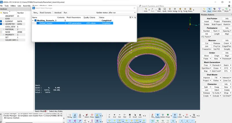
After the Batch mesh has been run some elements are failing for the quality, It is rectified by using the reconstruct and split option
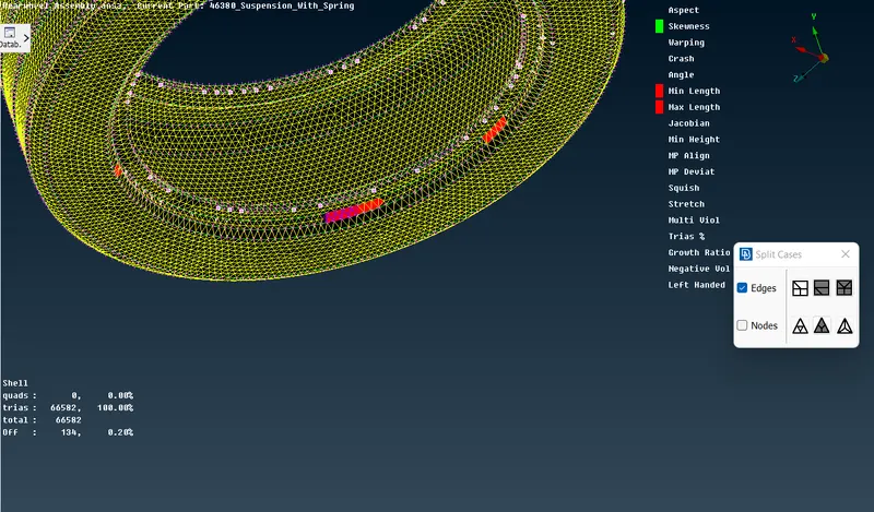
After rectifying the elements failing for quality criteria, volume meshing is done
Before Meshing can be done the part has to be assigned
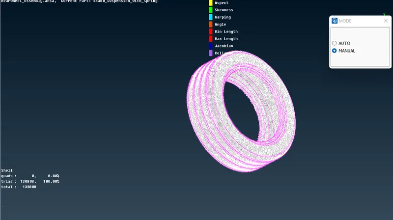
Once the model is assigned, volume mesh is done either by tetra rapid or tetra fem
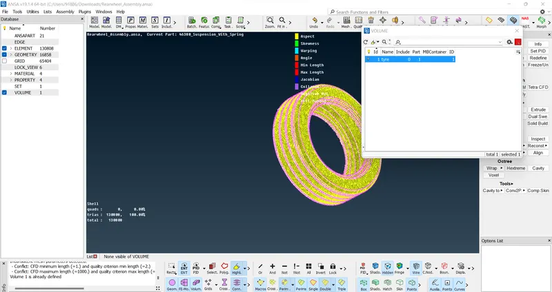
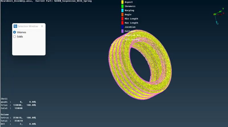
After Meshing there are some tetra collapsed. It is solved using the Fix Quality option
Final Volume mesh
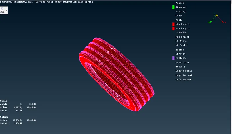
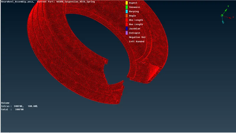
Similarly, Rim also meshed using the same process
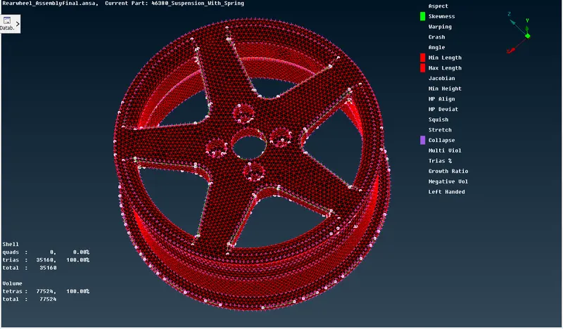
(Final mesh of RIM)
Mid Surface Generation for subframe and Macpherson strut outer surface
As per quality criteria, the components having a thickness less than 5mm has to be done through mid-surface and meshing(element type: MIXED)
Required quality criteria
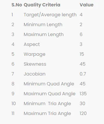
These components are either meshed through the casting method or by offsetting the plane manually and meshing using spot mesh or best mesh
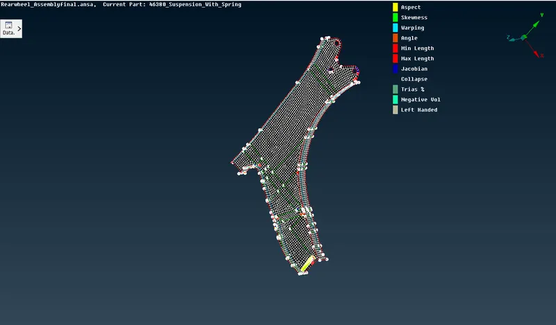
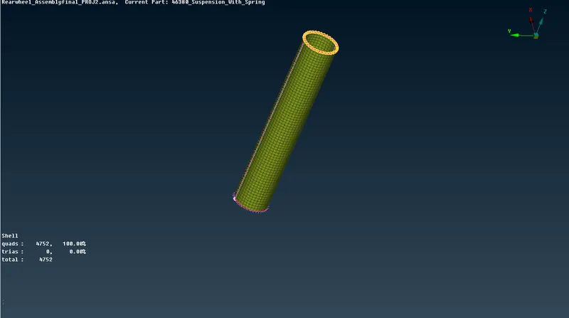
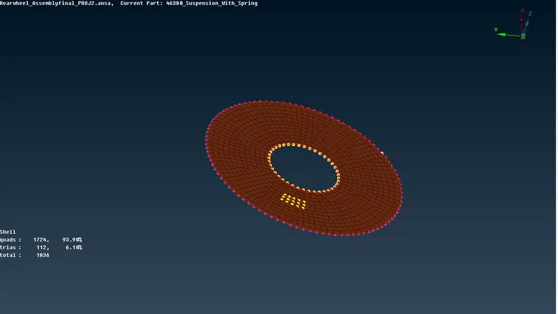
The elements failing quality criteria can be rectified using reconstruction or the split function
The meshing of components having a thickness greater than 5mm:
For the components having a thickness greater than 5mm volume mesh is done
Required Quality criteria
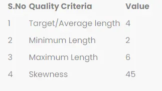
Similar to Tyre and Rims same meshing process is done for these components. The only difference is element length ie 4 instead of 6.25
Connections for rear suspension:
Once the volume meshing and surface Meshing are done and all the quality criteria are satisfied, Connections can be made
Connections can be made by using either blot, seam weld or spot weld methods.
The rigid connection can be made using RBE2 in the Nastran deck
The connection of the disc and brake to the rim is made using the RBE2 option in the NASTRAN deck as shown below
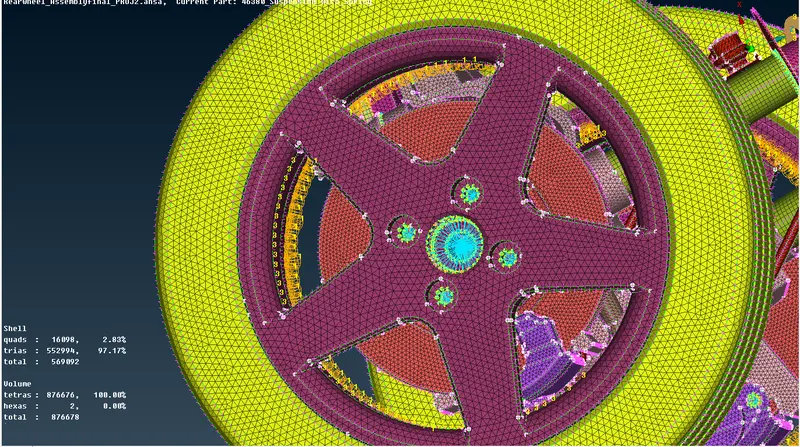
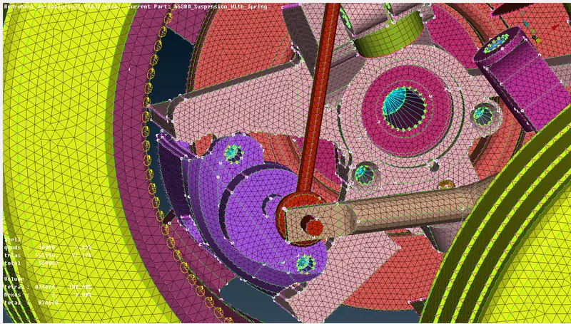
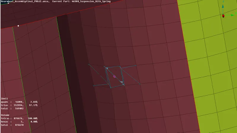
Some connection is made using Spot weld ie suspension and steering rack is connected using Spot weld
First COG is created and it is converted to Spot weld and connection is done using RBE3-Hexa-REB3
For the connection of Tyre and Rim CBUSh is made along the Tyre and RIM. The curve is created along the tyre and it is converted to a Spot line
The connection is made for the Spot line using RBE3-CBUSH-RBE3
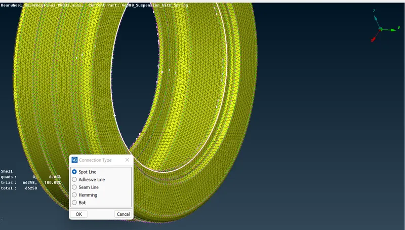
(The curve is converted into a Spot line)
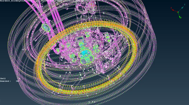
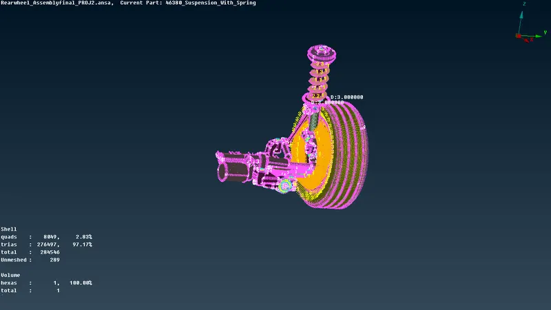
(Final Connection is Realised)
Mirroring the other half:
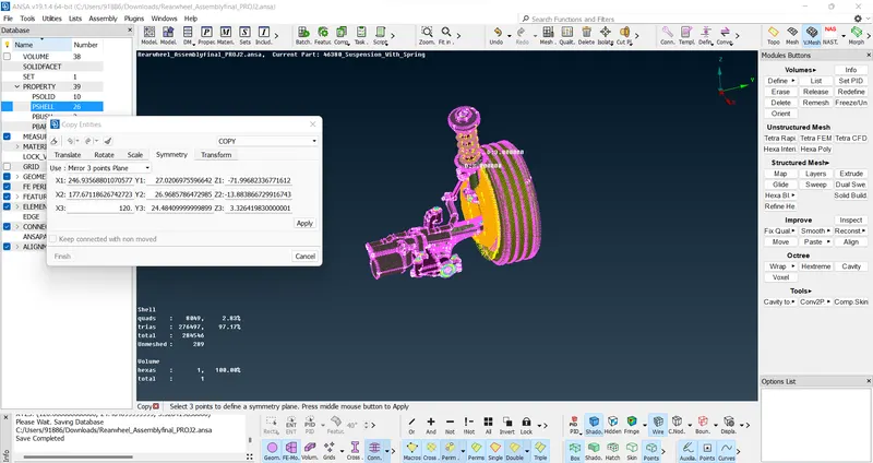
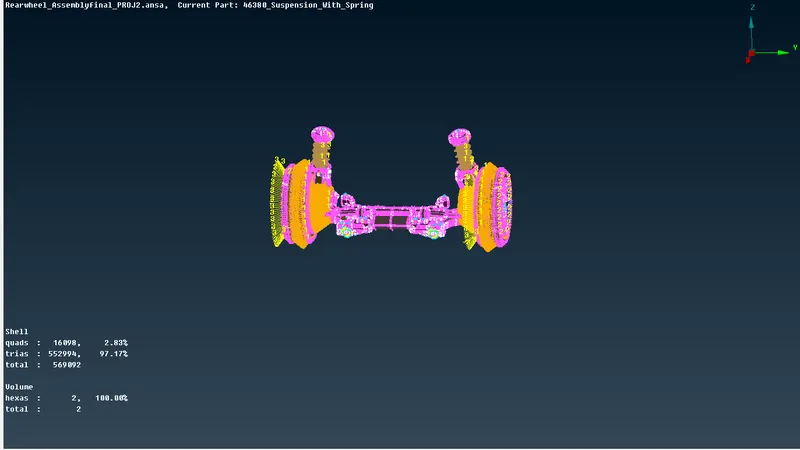
Since the imported Model is only half of the entire suspension system the other half has to be mirrored
It is important to make sure that all the Midsurface, meshing and connections have to be done before mirroring so that we can avoid doing Meshing and connections to the other half as it also can be copied to the other side as there are symmetric to each other and it saves time
Mirroring is done using the transform and copying the model using the mirror 3 points plane
Final Model:
Link for the Model: https://drive.google.com/file/d/1Mh3oxYqPZNFNtNR9h_52x6CzThbUmOU1/view?usp=sharing