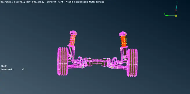
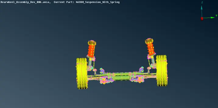
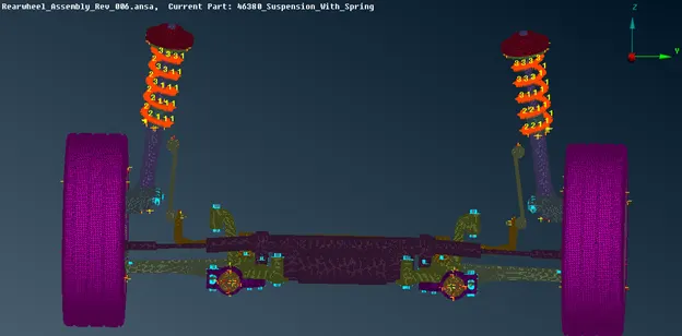
Meshing of a rear wheel assembly of an automobile by deploying connections for NVH analysis
MESHING OF A REAR WHEEL ASSEMBLY OF AN AUTOMOBILE BY DEPLOYING CONNECTIONS FOR NVH ANALYSIS
AIM:
The project aims to clean up and mesh the given rear wheel assembly parts according to the below mentioned criteria by applying thickness and to deploy suitable connections to perform NVH analysis.
Meshing criteria
- Volume mesh for Tyre and Rim using Tetra elements.
- Volume mesh for Non uniform thickness parts using Tetra elements.
- Shell mesh for parts having Uniform thickness below 5mm.
- Spring must be modeled as PBAR element.
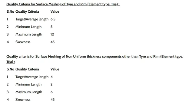
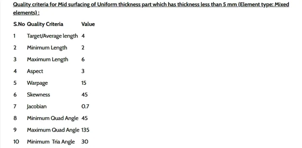
Quality criteria

PROCEDURE:
1. Import the given rear wheel assembly to ANSA and perform a topo so that any openings in the model will be eliminated.
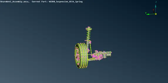
Fig: Imported model.
2. Since the assembly has multiple parts and has to be meshed with different approach according to the given criteria so it’s ideal to mesh the parts individually by isolating the other parts.
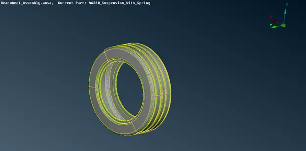
Fig: Isolated Tyre part.
3. Start with Tyre and Rim, Enter the element and quality criteria for these parts and save it.
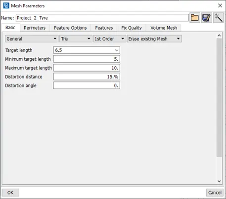
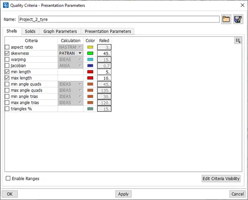
Fig: Element and Quality parameters.
4. Isolate only Tyre, check for geometry errors if found fix the issue. Any feature like fillet which is falling below the minimum element has to be toggled in order to avoid the elemental failures.
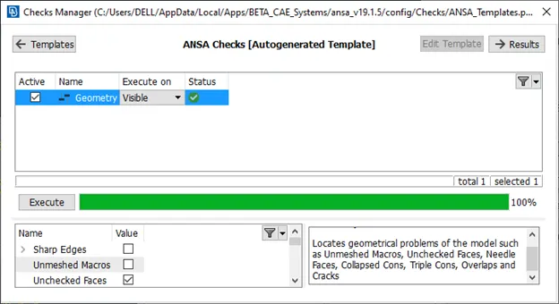
Fig: Geometry check.
5. Set the length to 6.5mm and mesh the surfaces using ortho tria element for curved surfaces and tria element for plain surfaces as shown. Make sure to capture the holes with even number of nodes.
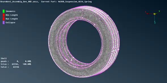
Fig: Surface Mesh.
6. Once done with surface meshing set PID and switch for volume meshing and define the volume.
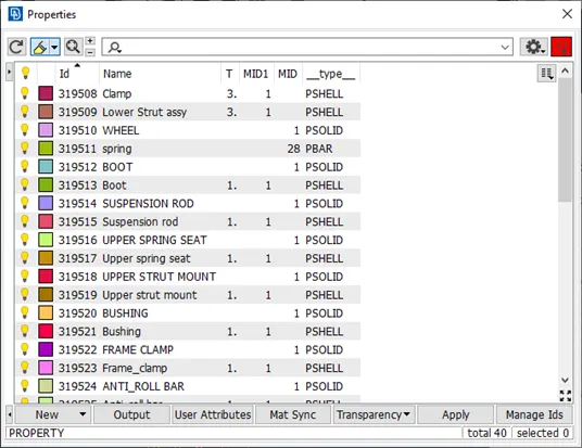
Fig: Assigning property.
7. Click for list and rename accordingly and set the PID with PSOLID element. Volume mesh the model using Tetra FEM.
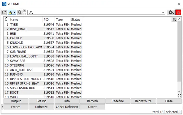
Fig: Volume List.
8. Check for tet collapse if found need to fixed.
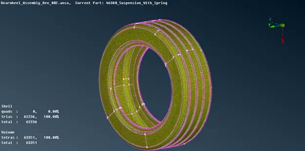
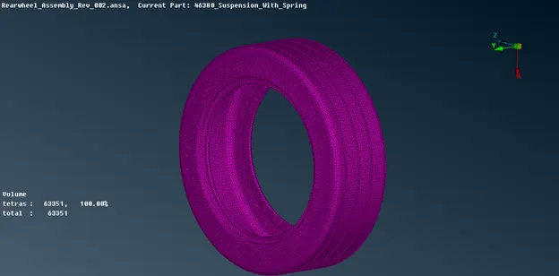
Fig: Volume mesh.
9. Repeat the same procedure for the Rim. Some of the elements will fail for its minimum in surface meshing of Rim due to the feature.
10. All the parts except lower strut part had non-uniform thickness so the criteria for these parts are different so change the element and quality criteria.
11. Perform the above mentioned steps for parts individually by isolating the other parts.
12. Toggle the unnecessary lines and make sure that no elements will fail for minimum.
13. Some of the surface corners need to be modified so has to avoid elemental failures.
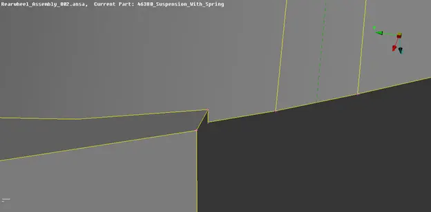
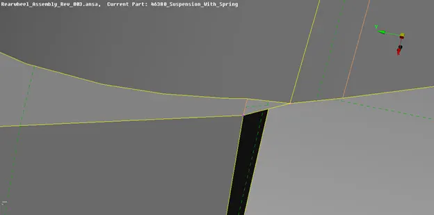
Fig: Surface modifications (Before and After).
14. The spring element need to be modeled using PBAR element so create a middle curve for the spring, connect them and create a COG point for the curve.
15. Measure the diameter of the spring.
16. Go to Nastran Deck and select CBAR. Check the orientation with the node and change to Curve(Box).
17. Select the curve and point and set element length to 4mm and set PID and enter radius value 5mm.
18. To view the elements change the presentation parameter to Line element cross section as solids.
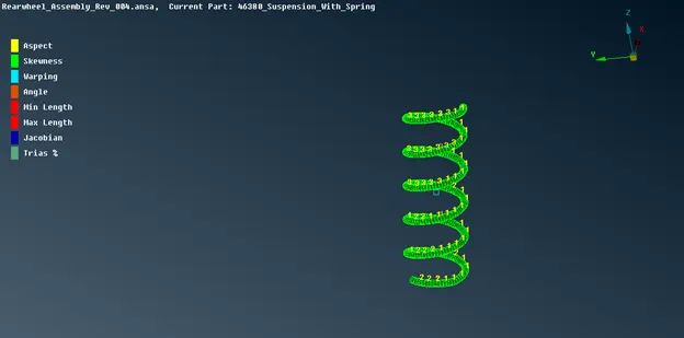
Fig: Spring Modelling using PBAR Element.
19. The Lower strut parts and clamp has uniform thickness of 3mm and need to meshed with 2D shell elements by extracting the mid surface.
20. Isolate the parts and offset the faces to 1.5mm and enter the element and quality parameters and mesh the surface.
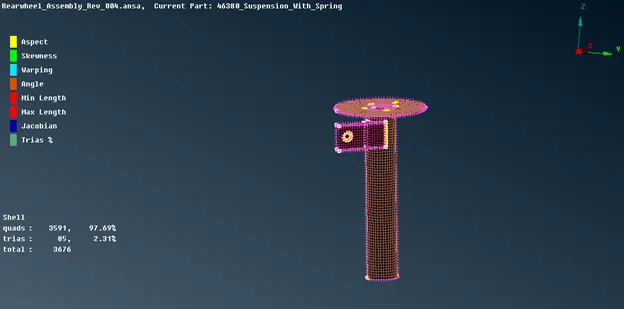
Fig: 2D shell meshing.
21. Once all the meshing completes apply suitable connections for the parts.
22. The clamp and lower strut must be joined using seam weld as shown in figure. The overlap shell joint is used.
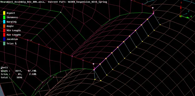
Fig: Seam Weld.
23. The parts like Hub, Knuckle, Whell Rim, Disc Brake, Caliper, sub frame, sub frame clamp, Ball joint, steering racks were connected with Bolted joints as shown in figure.
24. To apply bolted connection use RBE 2 multi node element to connect the holed nodes and 2 node RBE 2 elements to connect the master nodes of 2 different parts as shown. Make sure to restrict all DOF.
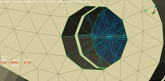
Fig: Bolted Connection.
25. The parts which has only holes and shafts like Ball joint, Anti-roll bars were connected using 2 node RBE2 elements as shown.
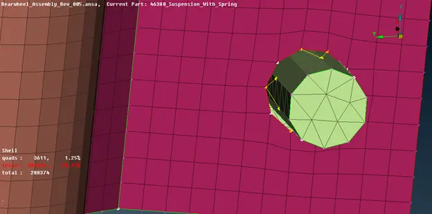
Fig: 2 noded RBE 2 Connection.
26. Connect the spring with the isolators using 2 node RBE 2 elements also the Tyre and Rim where connected using the same.
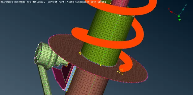
Fig: Spring connection.
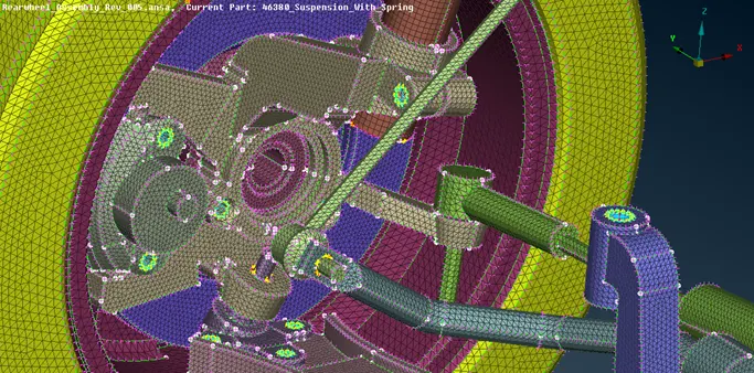
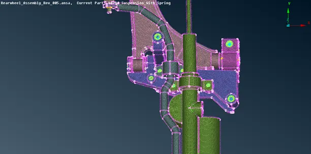
Fig: Connections.
27. Finally reflect the model using 3 nodes as reference plane as shown in figure.
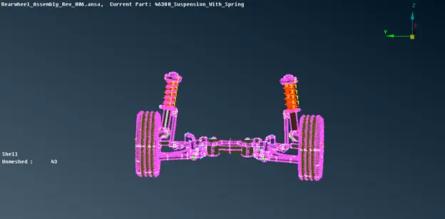
Fig Reflected model.
NOTE:
- Change the element length depending upon the quality and element parameters while meshing.
- Set Different PID for each and individual parts and volumes.
LEARNING OUTCOMES:
- Volume meshing of complicated parts.
- Surface modifications near to the sharp corners.
- Clearing of tet collapse near to the feature lines.
- Deploying connections at various locations.
- Modeling of spring element.
RESULT:
The Given model is meshed according to the given element and quality criteria and suitable connections were deployed so has to perform NVH analysis.
FINAL MODEL