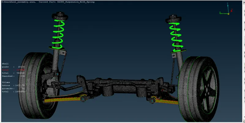
Project - 2 - Meshing on the suspension Assembly
Aim- To mesh the given component with suitable connections.
Obljective- To extract the mid surface for the suitable component.
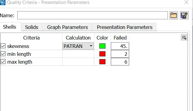
To mesh the tyre and rim component with the given quality criteria.
S.No Quality Criteria Value
1 Target/Average length 6.5
2 Minimum Length 5
3 Maximum Length 10
4 Skewness 45
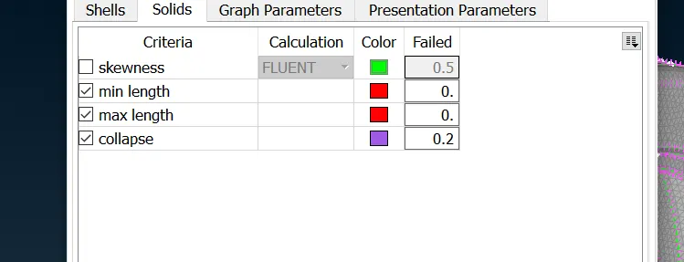
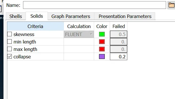
Quality Criteria for Volume meshing of all Non Uniform thickness components (Element type: Tetra Elements):
|
S.No |
Quality Criteria |
Value |
|
1 |
Tet-collapse |
0.2 |
Quality criteria for Surface Meshing of Non Uniform thickness components other than Tyre and Rim (Element type: Tria) :
|
S.No |
Quality Criteria |
Value |
|
1 |
Target/Average length |
4 |
|
2 |
Minimum Length |
2 |
|
3 |
Maximum Length |
6 |
|
4 |
Skewness |
45 |
|
S.No |
Quality Criteria |
Value |
|
1 |
Tet-collapse |
0.2 |
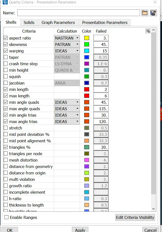
Quality criteria for Mid surfacing of Uniform thickness part which has thickness less than 5 mm (Element type: Mixed elements) :
|
S.No |
Quality Criteria |
Value |
|
1 |
Target/Average length |
4 |
|
2 |
Minimum Length |
2 |
|
3 |
Maximum Length |
6 |
|
4 |
Aspect |
3 |
|
5 |
Warpage |
15 |
|
6 |
Skewness |
45 |
|
7 |
Jacobian |
0.7 |
|
8 |
Minimum Quad Angle |
45 |
|
9 |
Maximum Quad Angle |
135 |
|
10 |
Minimum Tria Angle |
30 |
|
11 |
Maximum Tria Angle |
120 |
Procedure-
1. Import the component.
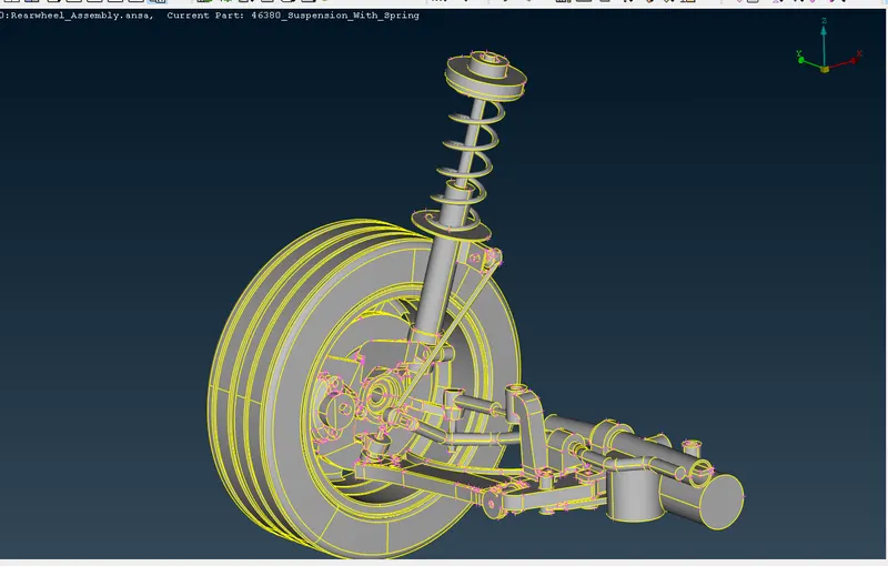
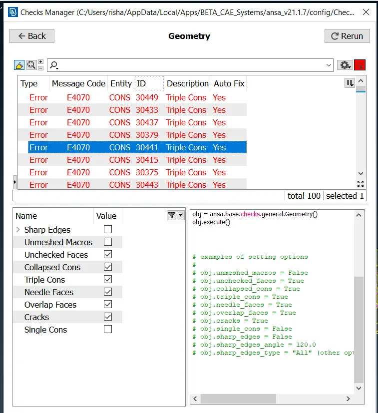
2. Check for the geometry errors and fix those errors.
3. Set the quality crietria for meshing the tyre and rim.
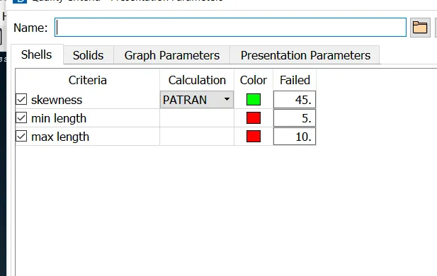
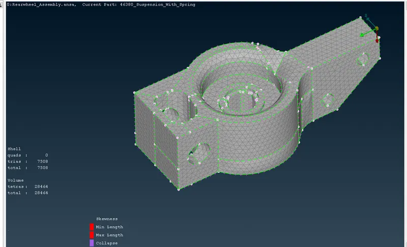
4.Start meshing the components of the assembly by applying the spot mesh from the mesh options. After the spot mesh in the 3d mesh panel define the volume and apply the tertra mesh for the component.
Clear the quality of the mesh by using the mesh tools.
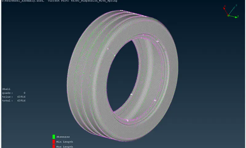
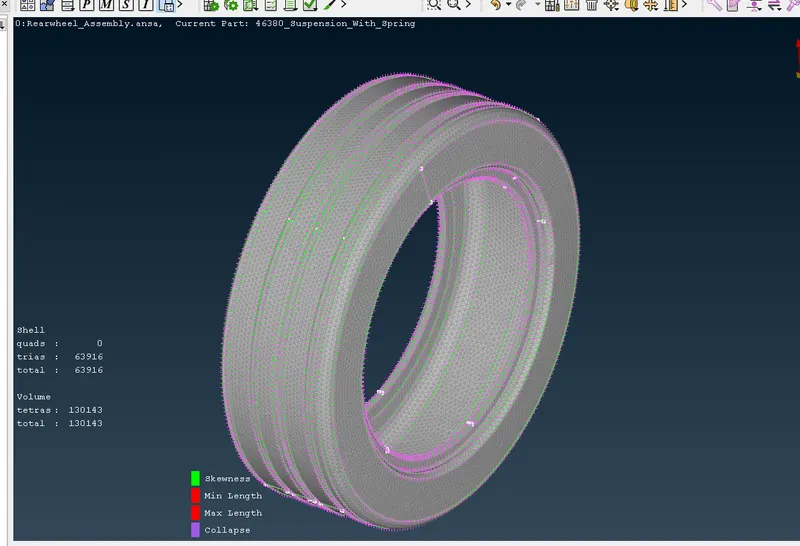
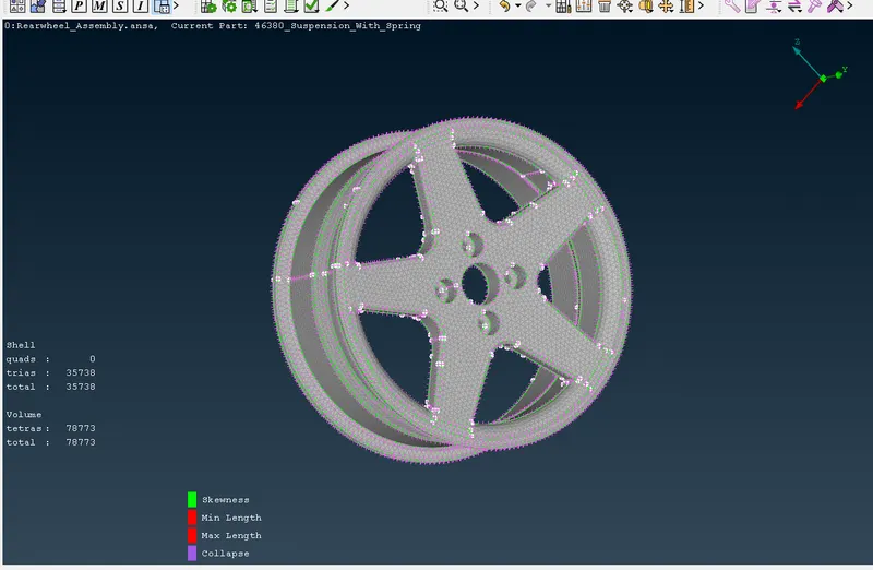
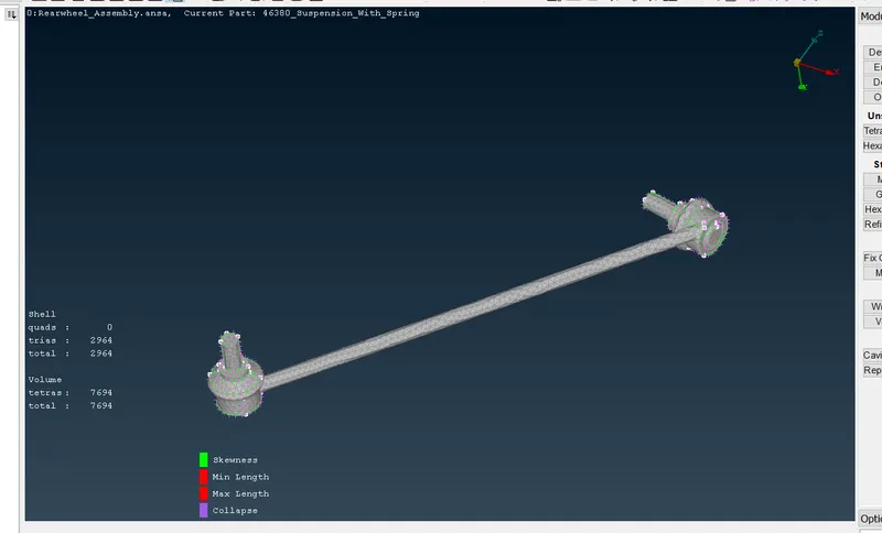
5. For the rest of the component st the different quality criteria and then mesh the component and fix the quality of the mesh.
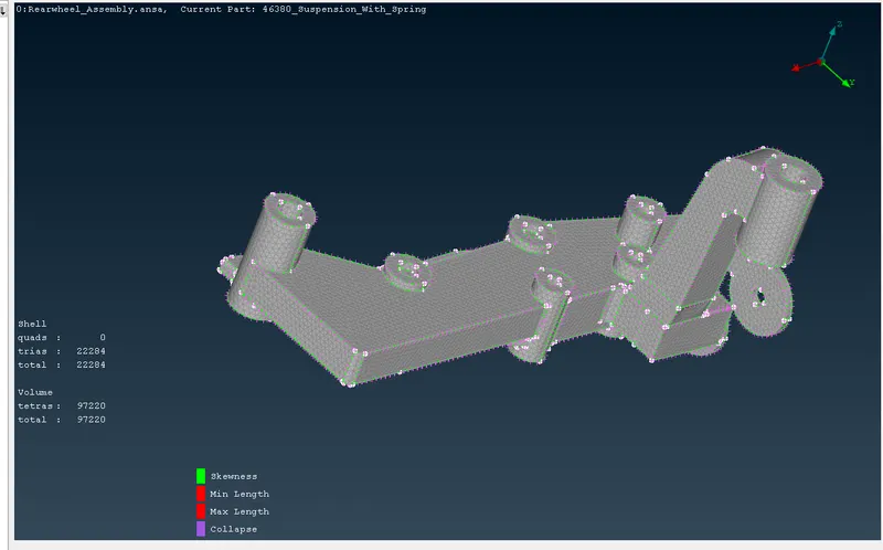
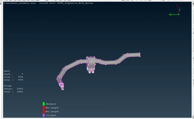
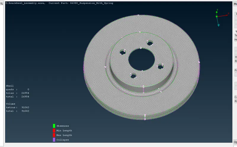
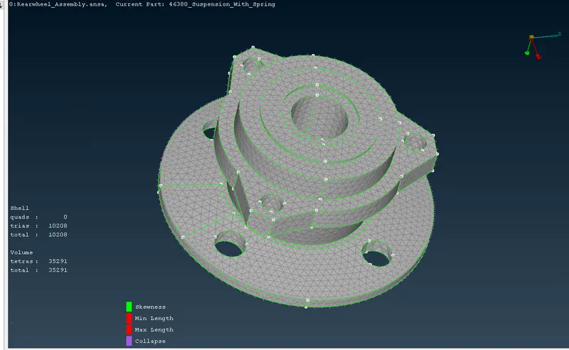
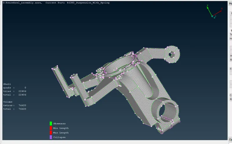
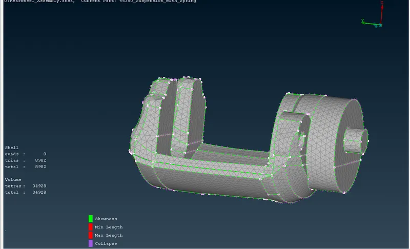
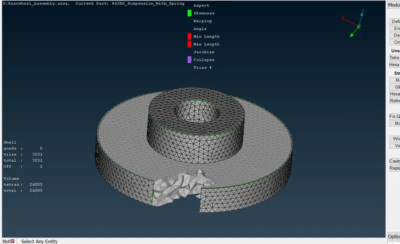
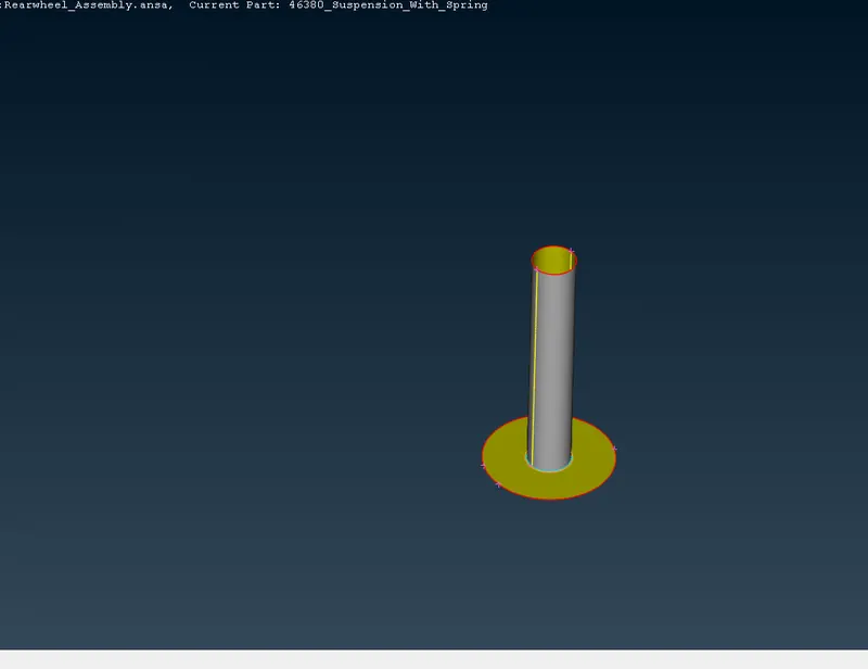
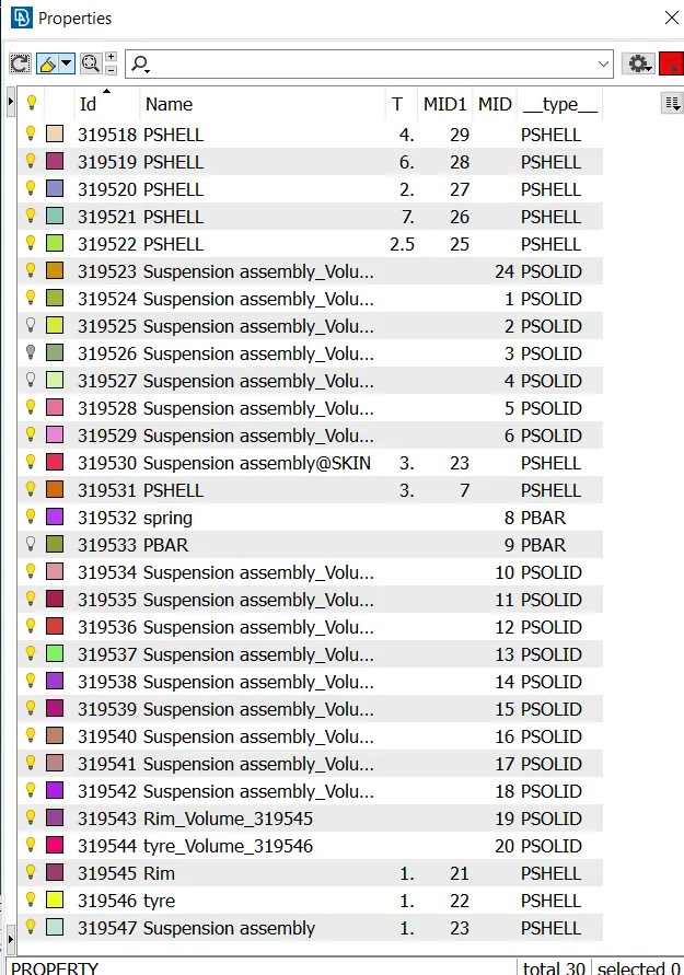
5. For the constant thickness model Extract the mid surface and set the pid for the mid surface with the suitable thickness.
The quality criteria for the mid surface meshing is given below.
6. For the sping element extract the middle curve.
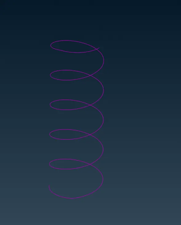
Connect all the curves forming one curve.
Create a COG pont for the curve.
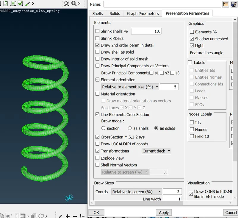
In the nastran tab select the CBAR element.
Select the curve and apply the elemnet thickness.
For the cross section area select the circular and set the diameter 5.
Click on ok elements will be formed.
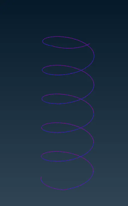
In the Presentation parameter turn on the line element cross section and click on apply and ok.
7. Set the connections for the suitable points .
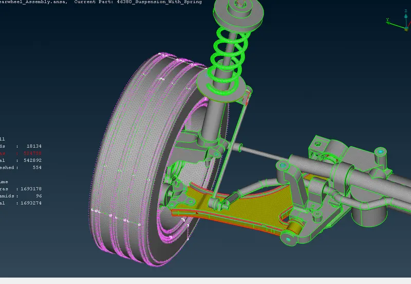
8. In the copy section select the components to be mirrored and select the plane along with the component needed to be symmetric.
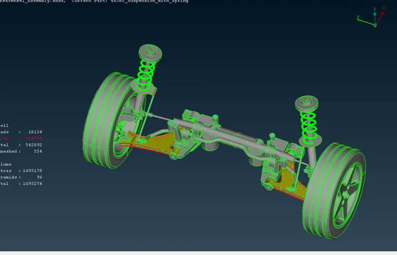
Result- In this project we have succesfully mesh the component.
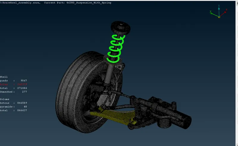
Conclusion - We have successfully applied the 3d mesh to the component.
We have extracted the mid surface of the component and applied the mesh to the mid surface.
we have maintained the quality of the mesh with the given criteria.
We have made the connections.
we have done the symmetry of the whole assembly.