Project - 2 - Meshing on the suspension Assembly
AIM:
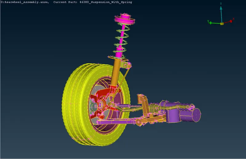
To check the geometry errors and mesh with the given quality criteria for the given CAD model and to assign thickness for the mid surface component. It is mentioned that mid surface is extracted only for components less than 5mm and for the remaining component we need to go for solid meshing.
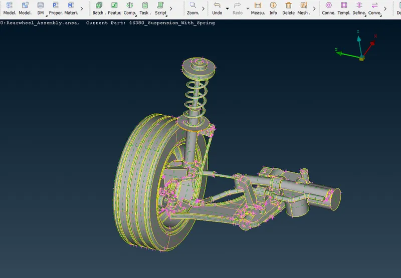
GIVEN CAD MODEL:
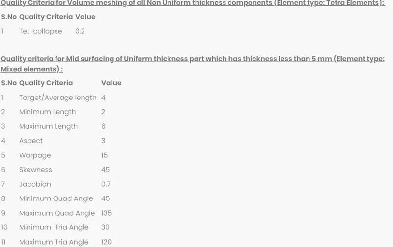
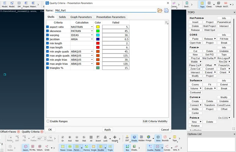
GIVEN QUALITY CRITERIA:

PROCEDURE:
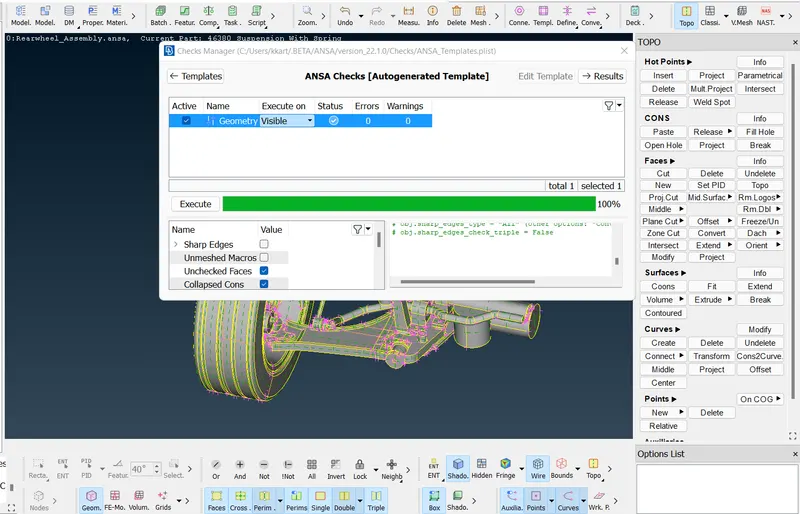
- The given model is in ANSA format so we do need to perform topo, now go to check>geometry>visible to check for the geometry error. Ansa will check all the visible geometry and if any error is there in the geometry ansa will show the error and if any auto fix option is available you can select all the errors and right click and select the auto fix option. Once you cleared all the errors, ansa will show green tick in the status.
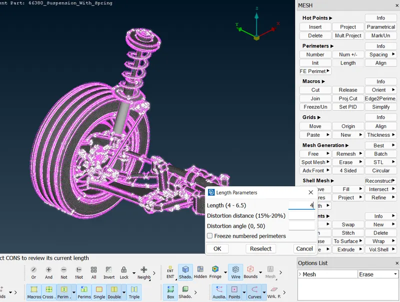
- Once you clean up all the geometry errors, now it is time to set the resolution. A good resolution will give precise curves and surface visibility without dents. For that go to mesh module under perimeters tab go to length>select the entire cad model>enter the target element size as resolution and click ok. Similarly for the macros.
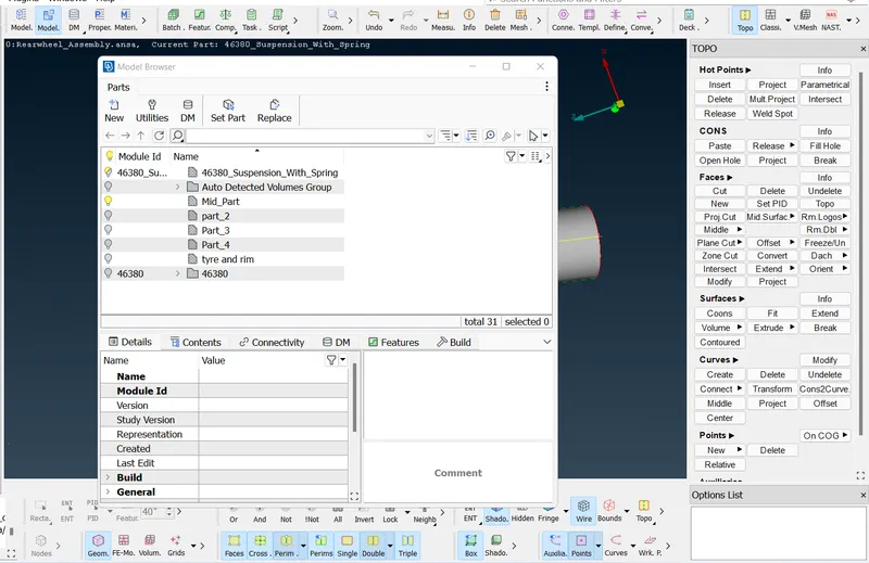
- Since this component was an assembly of parts. we need to measure thickness and set pid for each parts. For that go to not>selection as pid region>select the particular part>click invert>now go to set PID under macros> select the part >give middle mouse click>create new pid>enter thickness value and click ok.
- For measuring thickness for all the component use weld points under hot points in topo module to find the exact distance between the two surface. After creating a weld point on one surface project it to the other surface. Now go to measure select the two weld points give middle mouse click now you can identify the thickness between the two surface
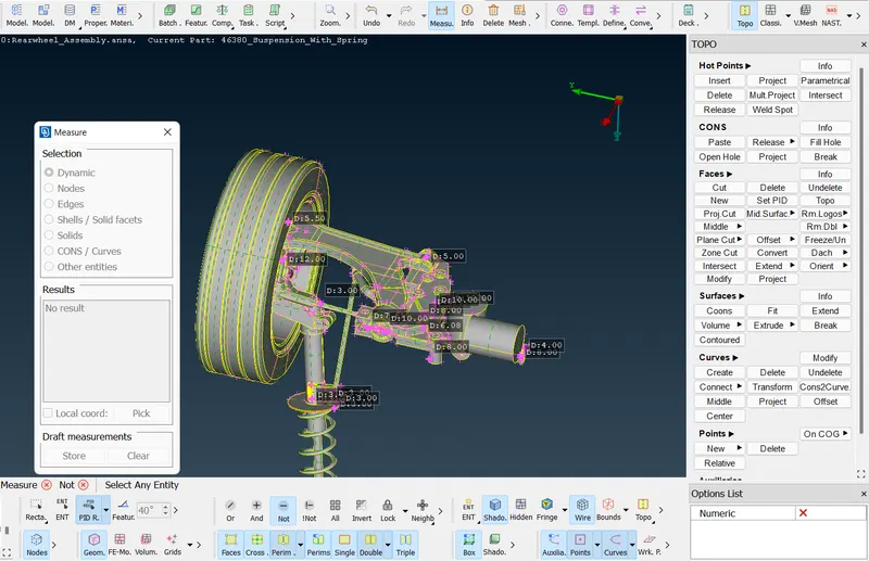
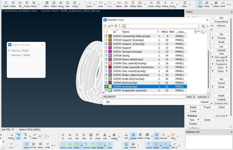
- After measuring all the components thickness, we can see that only two components are less that 5mm thickness and remaining all the components are greater than 5mm. So the components less than 5 mm is needed to extract the mid surface and perform 2d mesh.
- for extracting mid surface for this component i use midsurface>skin option as the thickness of that component is uniform through.
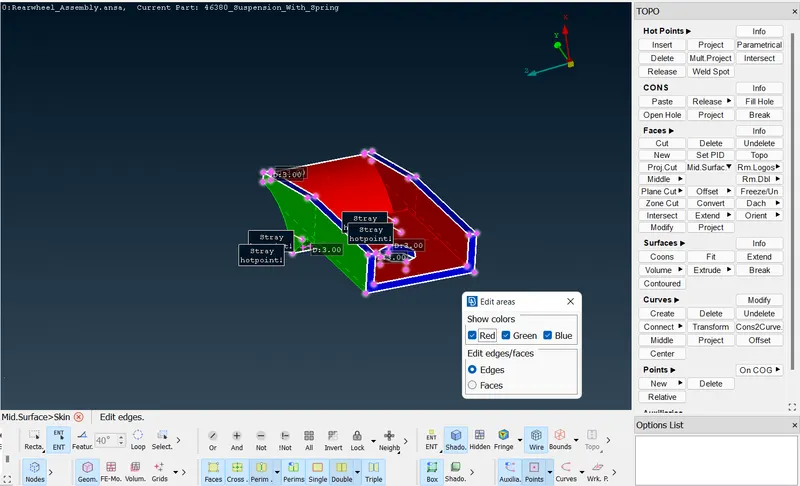
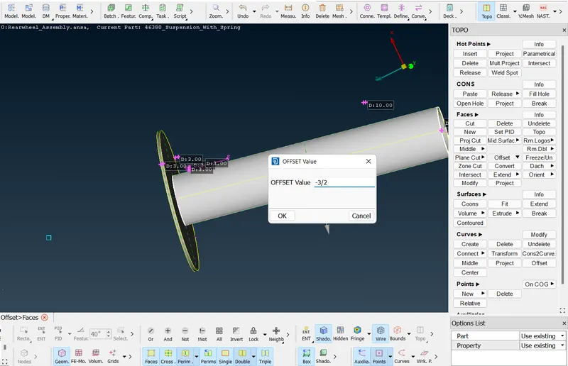
- Another component has the same 3 mm thickness but it has some intersecting faces so i go for offset option. Go to topo module>faces>offset> enter thickness give ok.
- Once the mid surface is created for the components with thickness less than 5 mm, we need to perform 2d mesh. Before that go to mesh parameters and give 4 as target element size and minimum size as 2 and click ok.
- Go to quality criteria and enter all the given criteria and click apply and ok.
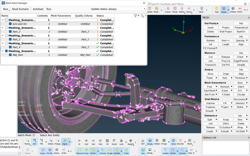
- For performing batch mesh create a new part the assign the mid surface to it. Now go to batch mesh>new mesh scenario>select the component> select the required mesh parameters and quality criterias and click run.
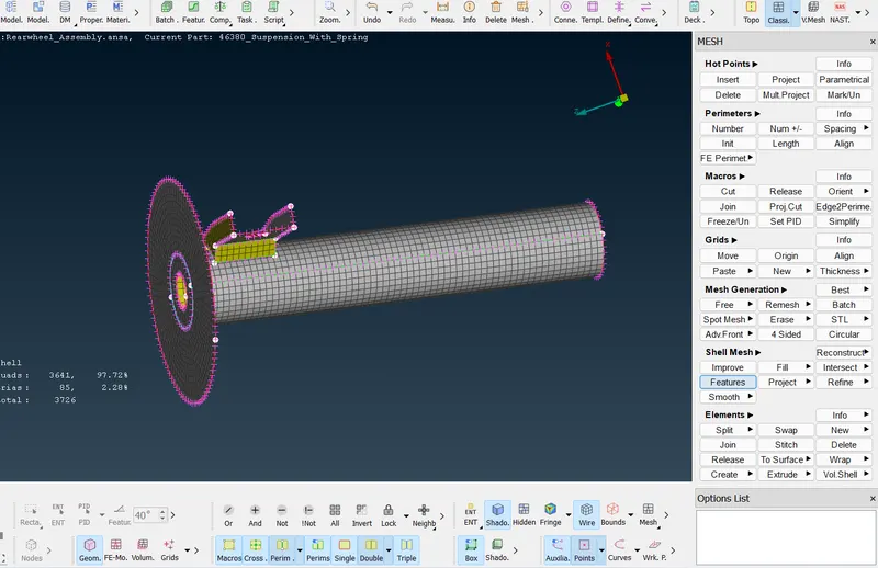
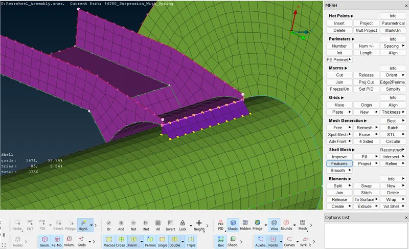
- Now to perform connection between these two components first create a curve on the edge of the component for that go to features to curve and select the perimeter. Now go to convert curves>select the seam line and click ok. Now go to connections manager and select that connection and select the pid for these two components and in the right side of the window select overlap shell>give search distance as 20>select width as target element size>select double row > click apply and realize.
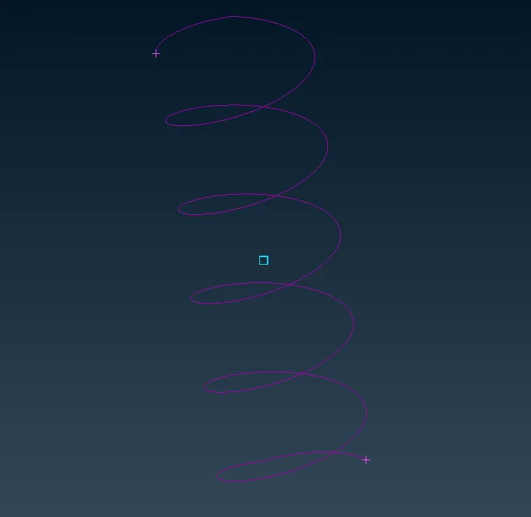
- As recommended, we need to represent the spring as a 1D bar element. for that first create a curve>middle to generate a middle curve for spring and go to Points>ON COG, select the curve and give middle mouse click thus a 3D COG point is created.
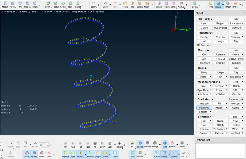
- Now for creating a bar element, go to nastran module under elements go to cbar elements>curve(box)>check that orientation with nodes check box and select the curve now select the cog point as node for orientation. now specify the element length as 3mm now give a middle mouse click. create a new pid for that bar element under area do shift + ? and enter the diameter as 10 mm as measured and click ok.
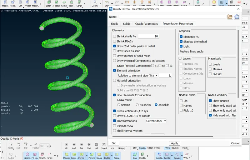
- To visualize the 1D bar representation in 3D go to quality criteria under presentation tab check the line element cross section and select "as solid" and click apply and ok.
- Now we move on to the components with thickness greater than 5mm for those components we perform solid meshing so now change the mesh parameters and mesh quality criteria recommended for solid meshing.
- Before that we need to create a 2d mesh elements on the surface for that go to batch mesh create new criteria>select the part that we need to perform the batch mesh >selected the required mesh parameter and quality criteria and click run.
- Now go to volume mesh module>volumes>define>visible and ok. Now under unstructured mesh>go to tetra rapid>select all the volumes that you have defined and click ok. Now if you see the list you can understand what are all the volumes detected and what algorithm is used for meshing.
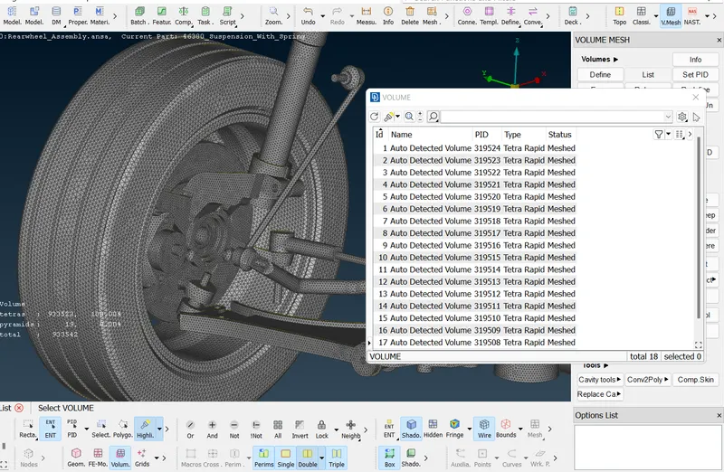
- Thus the meshing part is done for all the components in the assembly.
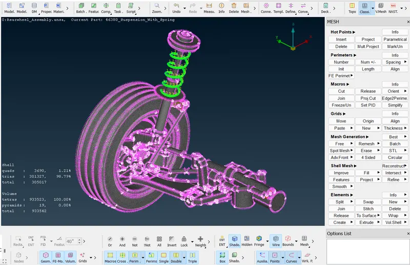
- FINAL MESHED MODEL:
RESULT:
Thus for the given assembly cad model, geometry check is done and mid surface is extracted for components less that 5mm and solid mesh is done for components greater than 5mm under the given quality criteria and for the given spring cbar element is created and represented it as a 3D element.