Project - 2 - Meshing on the suspension Assembly
Objective:- Do the following operation on the given model:-
a. Check the geometrical errors.
b. Mesh the component with the given quality criteria.
c. Assign thickness after meshing.
d. Use tetra elements for non uniform thickness component.
e. Use appropiate connections to connect the connections.
f. Use transform options to reflect the components on the other side.
Quality Criteria for Surface Meshing of Tyre and Rim (Element type: Tria) :
|
S.No |
Quality Criteria |
Value |
|
1 |
Target/Average length |
6.5 |
|
2 |
Minimum Length |
5 |
|
3 |
Maximum Length |
10 |
|
4 |
Skewness |
45 |
Quality criteria for Surface Meshing of Non Uniform thickness components other than Tyre and Rim (Element type: Tria) :
|
S.No |
Quality Criteria |
Value |
|
1 |
Target/Average length |
4 |
|
2 |
Minimum Length |
2 |
|
3 |
Maximum Length |
6 |
|
4 |
Skewness |
45 |
Quality Criteria for Volume meshing of all Non Uniform thickness components (Element type: Tetra Elements):
|
S.No |
Quality Criteria |
Value |
|
1 |
Tet-collapse |
0.2 |
Quality criteria for Mid surfacing of Uniform thickness part which has thickness less than 5 mm (Element type: Mixed elements) :
|
S.No |
Quality Criteria |
Value |
|
1 |
Target/Average length |
4 |
|
2 |
Minimum Length |
2 |
|
3 |
Maximum Length |
6 |
|
4 |
Aspect |
3 |
|
5 |
Warpage |
15 |
|
6 |
Skewness |
45 |
|
7 |
Jacobian |
0.7 |
|
8 |
Minimum Quad Angle |
45 |
|
9 |
Maximum Quad Angle |
135 |
|
10 |
Minimum Tria Angle |
30 |
|
11 |
Maximum Tria Angle |
120 |
PROCEDURE:-
STEP-1
Import the cad file to the ANSA.
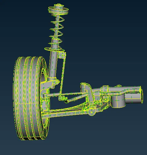
STEP-2 :-
After importing the file go to mesh mode give length as 1 unit in perimeter option for cons resolution.
Then give TOPO if it is IGS file and orient for color resolution.
After all this complition go for geometry check.
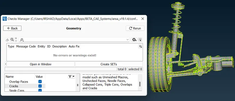
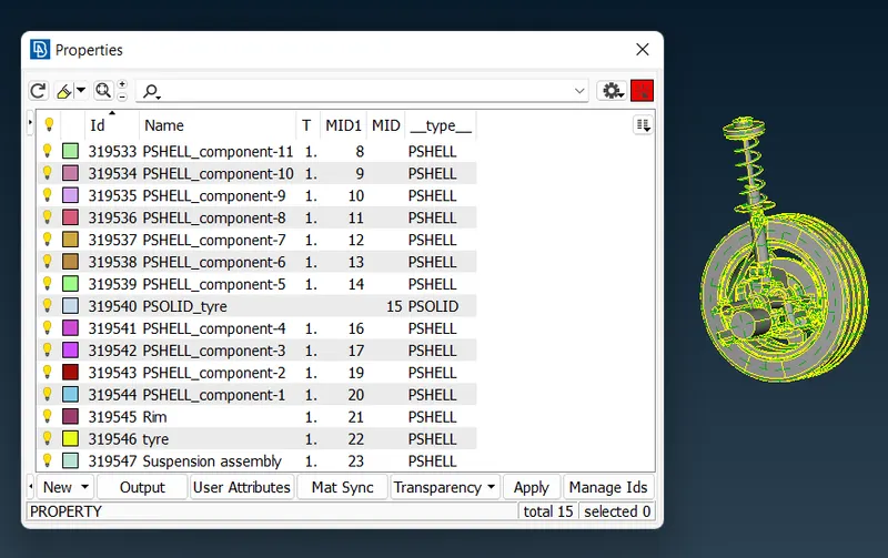
STEP-3:-
Since the assembly is larger set the different-different PIDS for the component to get the operation smoothly.
STEP-4:-
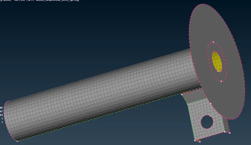
Component 11 has thickness less than 5mm, for these component we have to extract the mid surface using offset method.
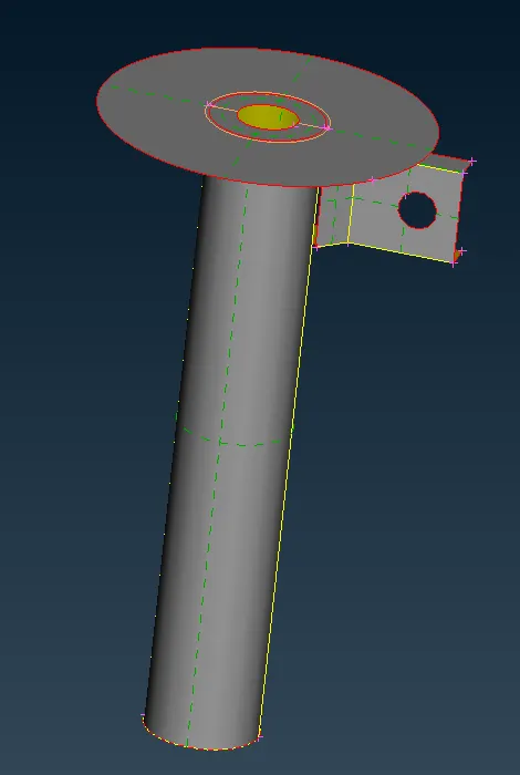
After extracting the mid surface assign the mesh parameter and quality criteria and the component.
STEP-5:-
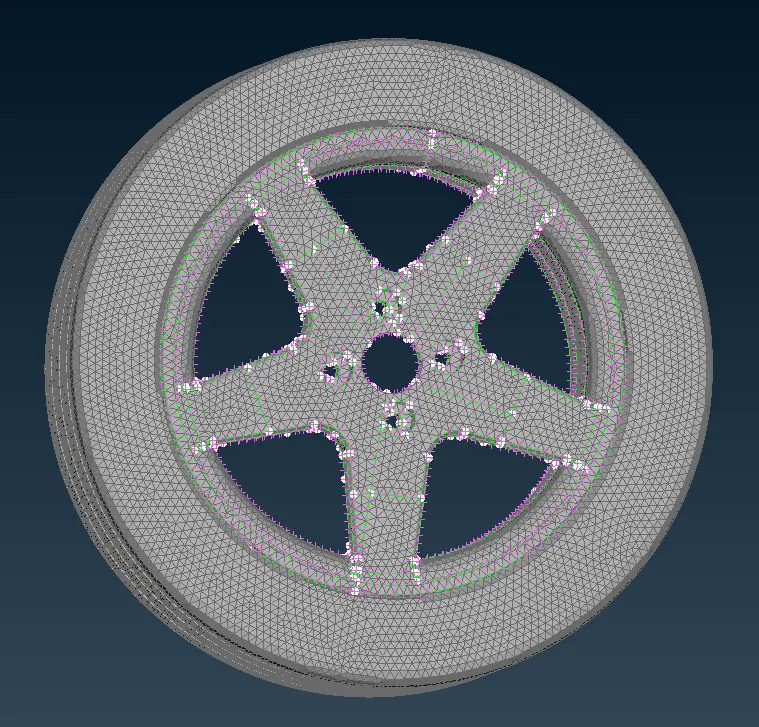
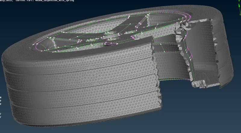
For tyre and rim volume has to be performed,for that mesh the component as shell using tria element and given quality criteria and mesh parameter then go to volume mesh module select manual in the define option.Before move for volume mesh assign all the quality and collapse value.(Define-manual,then list-edit-rapid tetra element-then remesh).After meshing make sure collapse element must be improved(Improve-fix quality-visible).
STEP-6:-
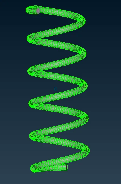
In component 3,there is spring in the assembly that we have to represent as a 1d bar element.
For that extract the middle using middle commamd in the curve option.(curve-middle-first curve middle click-2nd curve middle click,then curve-connect-multi,then creat CoG point,after that go to deck module select CBAR elementthen select the curve and give middle click then select CoG point and assign the element length as 3mm then create the separate PID's for bar and spring and represent as solid through line representation in presentation parameter).
STEP-7:- Rest all components are meshed as a volume mesh beacause each one has thickness more than 5mm.
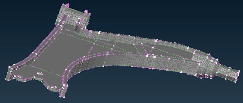

STEP-8:- After complting the mesh part go for the connection part for the component, for this assembly mostly we use bolt and weld connection.
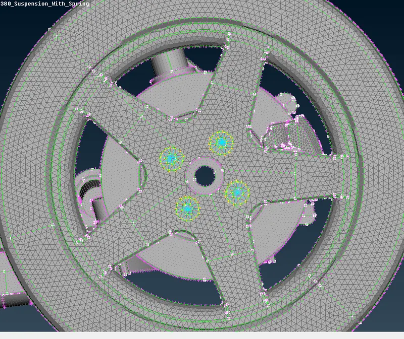
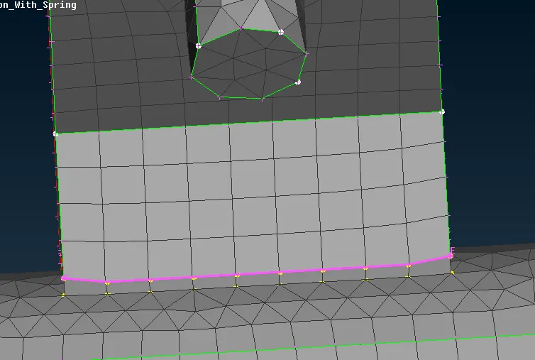
STEP-9:- After compliting the connection assign the thickness for the components then transform it with the help of three point plan.
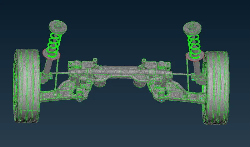
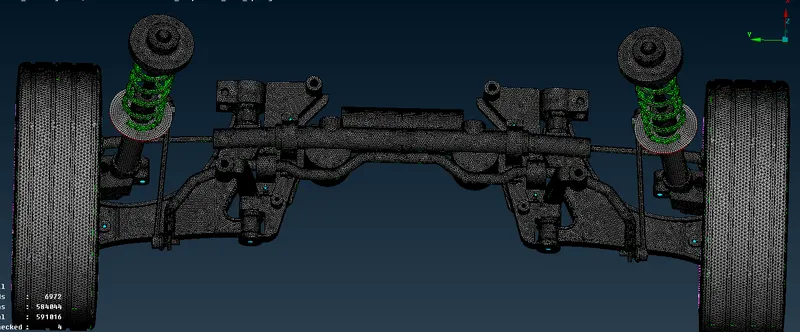
RESULT:-
LEARNING OUTCOME:-
a. Get to know about the assembly.
b. Get to know creation of 1D bar element from spring.
c. Work on Solid mesh as well as shell mesh (using mid surface creation)
b. Work on Connections like bold and seam weld.
e. Get to know about transform option using three point .
https://drive.google.com/file/d/1yz5DNixTt5tsSC020gt1h4NHcSSqb-Mn/view?usp=sharing