Week 4-1D Element Creation Challenge
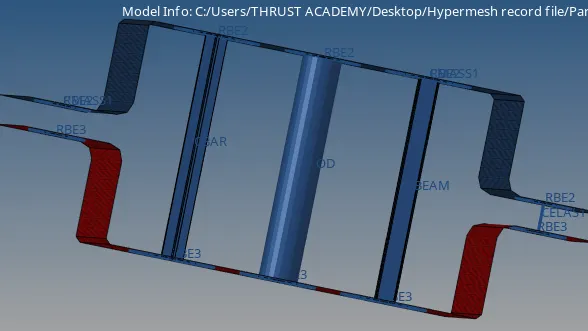
Objective:- To mesh the given component with the size of 5 units. Create 1D elements on the following components with the given cross-section and DOF.
a. Rod element:- Translational DOF should be Constrained with RBE2 link
Cross-Section: BOX- Dimension a= 12 mm
dimension b=10 mm
Thickness t= 0.75 mm
b. Beam element:- All DOF should be constrained with RBE3 link
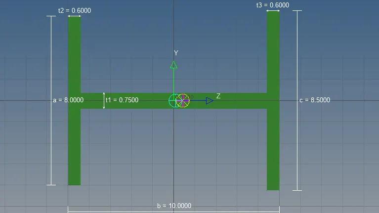
Cross-Section: I Section- Dimension a= 8 mm
Dimension b= 10 mm
Dimension c= 8.5 mm
Thickness t1= 0.75 mm
Thickness t2= .6 mm
Thickness t3= .6 mm
c. Bar element:- Constrain only x and y DOFs With RBE3 link
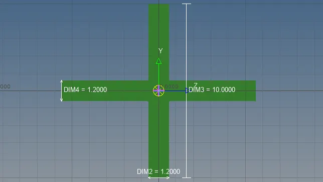
Cross-section: X section- Dimension DIM1= 5 mm
Thickness DIM2= 1.2 mm
Dimension DIM3= 10 mm
Thickness DIM4= 1.2mm
d. & e. Apply the mass of magnitude 10 with the RBE2 link
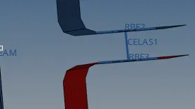
f. Join the two components with Spring elements
Introduction about 1D, RBE2 link, RBE3 link:-
1D:- 1D elements are basically line-shaped elements that are created by two nodes. Examples of 1D elements are RBE2, RBE3, ROD, BAR, BEAM, Spring Elements.
(1D elements are used when one of the dimensions is very large as compression to the other two i.e long shaft, joints, pin joints, beams, connection elements).
Some important points about the RBE2 link;-
1. RBE2 link:- These are basically elements, which will have infinite stiffness(i.e This element will never bend and move when the load is applied).
2. Load transfer through the RBE2 link will be constant.
Some important points about the RBE3 link:-
1. It can be moved up, down, forward, and backward as per applied load.
2. RBE3 link can be created the same way as the RBE2 elements.
. Procedure:-
→ Import the model and delete the unwanted lines.
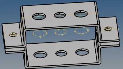
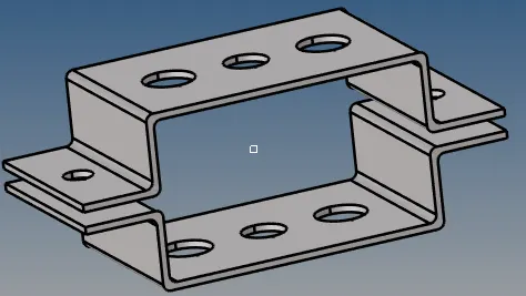
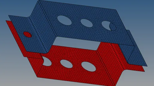
→ Firstly, need to create a mid surface(commands-Geo↵mid surface↵auto midsurface+auto extraction, extraction option set on skin offset then again go to auto extraction and click extract)
→ Rename the mid surface as Bracket-1 & Bracket-2 separately and again create the mid surface for the lower bracket.
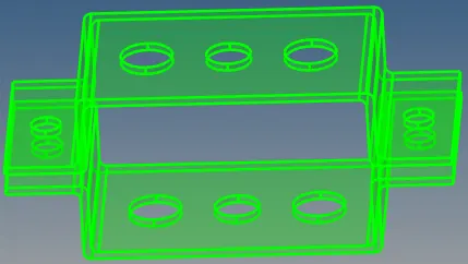
→ Then go to the delete option select solid and select the surface and delete the entity.
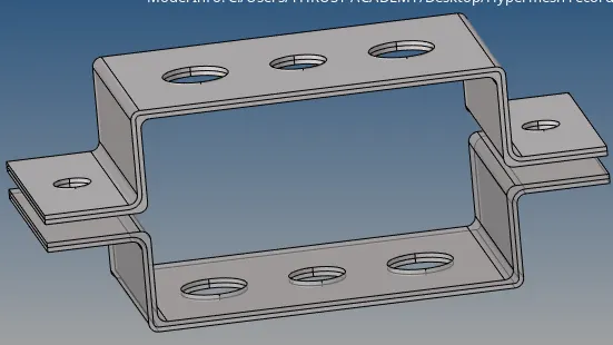
→ Delete the auto-generated body(i.e body 0&1) in the component section (right corner)
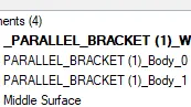
→ After deleting the auto-generated body, ll get
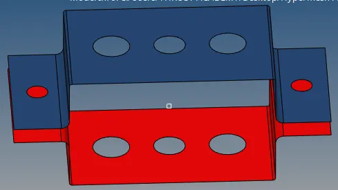
→ Now, move the mid surface to bracket-2(command- tool↵organize↵collectors↵surface, dest component bracket_2 then go to move option) and delete the last created mid surface.
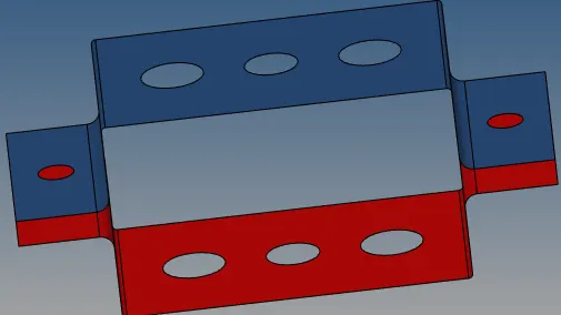
→ The mid surface is nothing but the 2D representation of the 3D component. For that need to assign the material and properties of the materials.
→ For that go to the right corner of the display right-click and add the material as a steel
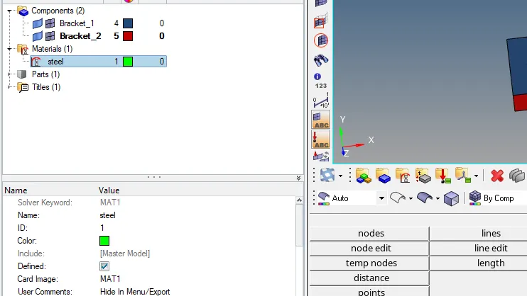
→ Create the separate properties for each bracket and assign them to the respective components.
→ Before going to the auto mesh in 2D tool go to quick edit and select washer split
→ Then go-to auto mesh with element size 5mm(2D↵auto mesh↵size and bias,surface+display+mesh type mixed+element size 5mm then go to mesh)
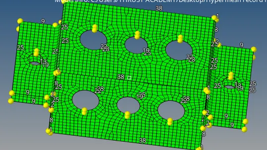
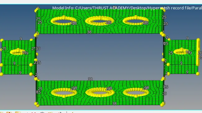
→ Now create a 1D element (reasons to go auto mesh before the creation of 1D element is to get the nodes)
→ Next, create an RBE2 link( 1D↵rigid↵create↵calculate node+multiple node+by path then go to create)
→ For rod, Translational DOF should be constrained with RBE2 link.
→ For beam, all DOF should be constrained with RBE3 link
→ Apply the mass of magnitude of 10 with the RBE2 link
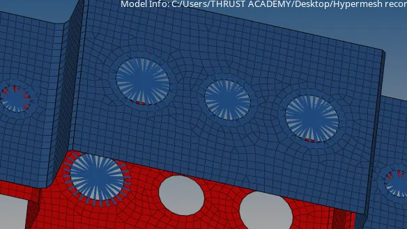
→ Now create the RBE3 element( 1D↵RBE3↵calculate nodes+by path then create)
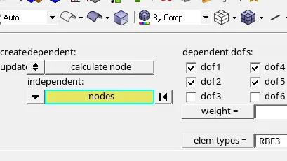
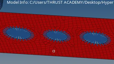
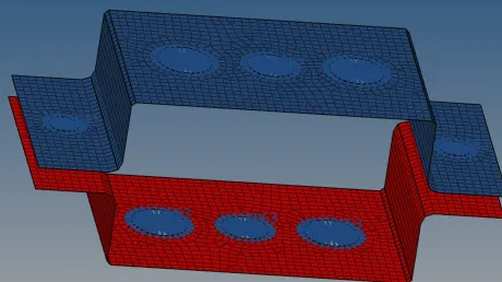
→ After creating RBE2 & RBE# link create a cross-section of the hyper beam like BOX, I section & Cross, as per the given dimensions( command- 1D↵hyper beam↵standard section↵hyperbeam+thinwall box) for I section(1D↵hyper beam↵standard section↵hyperbeam+standard I section then go to creat option) & for cross-section (1D↵hyper beam↵standard option↵optistruct library+cross then go to create option).
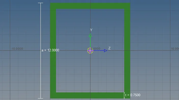
→ Now create the rod, beam, and bar section. (command- 1d↵bars↵select the nodes where to be created+set the property & element type).
→ For rod ( 1D↵rods↵two nodes where the rod to created).
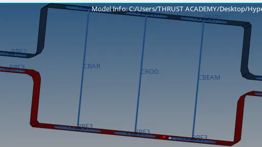
→ For cross-sectional view go to the menu bar select 1D traditional and detailed element representation.
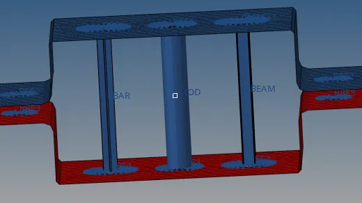
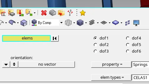
→ For springs create the spring property 1st then go to 1D↵springs↵select the nodes where the springs have to be created then set the property and element type.
→ Now apply the mass of magnitude 10 with the RBE2 link.
Conclusion:-
1. Through this session I have learned about RBE2 & RBE3, bar, rod, beam, and how to extract mid surface.
2. And also gain some idea about 1d elements and some hypermesh tools like hyper beam(creation of I section, box, cross-section, and many more sectional views).
3. Learnt some new commands like springs, mass, rigid in 1D tool and how to assign the material properties to the respective cross-sections.