Project - 2 - Meshing on the suspension Assembly
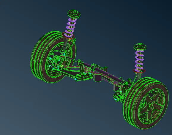
AIM: To perform the appropriate meshing on the given Rear wheel assembly by following the given Quality Criteria.
MODEL:
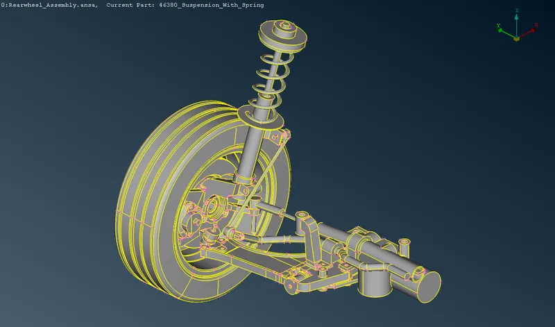
PROCEDURE:
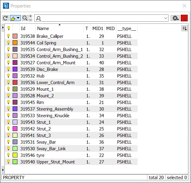
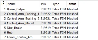
1. All the suspension parts are found to be defined within a single PID, hence, the different parts are assigned to different PIDs using the ‘Set PID’ tool.
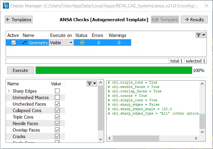
2) Geometry Cleanup
The geometry check is done using the Checks Manager available under, Tools>Checks>Geometry.
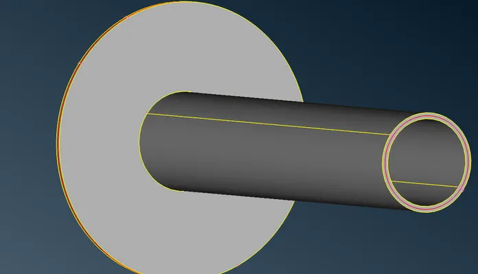
3. Mid surfacing of the model
mid surface is extracted using manual offset method. Under Faces>Offset
4. Meshing 2D
Meshing is performed using the ‘Best’ option under ‘Mesh Generation’
Quality criteria is also set for meshing.
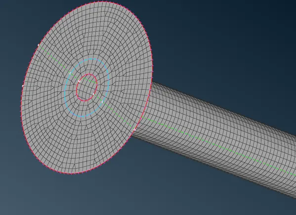
meshing improved by Reconstruction , improve, Smooth options
Also Swap, Split and join also used to improve meshing
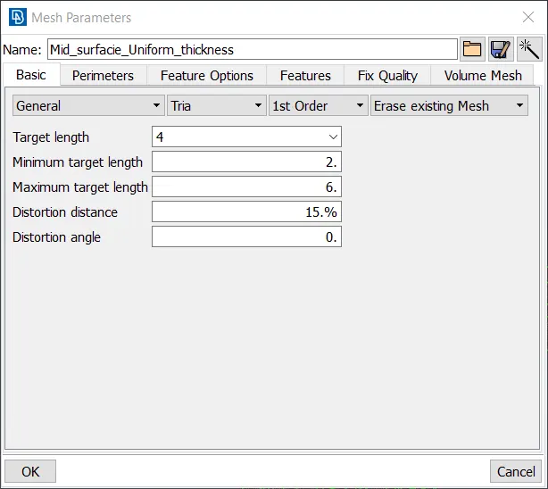
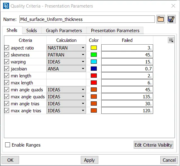
after meshing
5. Meshing 3D
For performing tetra meshing, the surfaces of the component have to be initially meshed with Tria elements.
The given quality criteria’s need to be specified using the criteria file editor before meshing the model.
after meshing the tyre parts
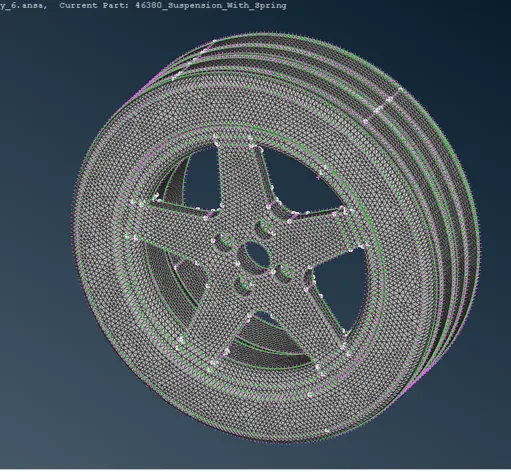
Check for failing elements for the given quality criteria’s. If any element is found to be failing the given quality criteria then the required cleanup is done to correct them.
After performing 2D meshing on the component with Tria elements, to perform 3D tetra meshing on the components, each of the component has to be defined as an enclosed volume. The volume can be defined using the ‘Define’ option present under Volume Mesh>Volumes.
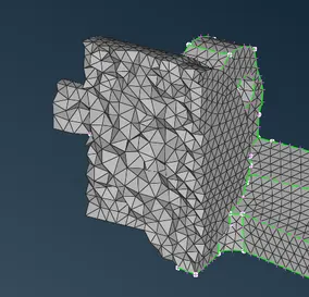
Check if any tetra elements are failing for Tet Collapse.
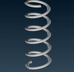
6) Modelling of Spring
The suspension spring is modelled using Bar elements. For this first, a curve is created in the middle of the spring using Topo>Curves>Middle.
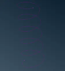
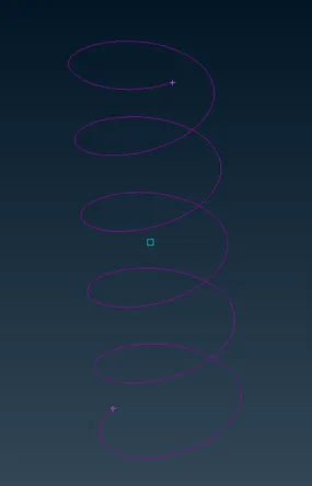
Using the curve as reference the PBAR element is created from Nastran Deck>Elements>CBAR. A new PID is also created for the CBAR element
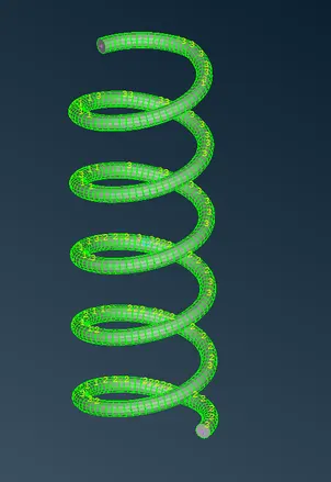
7) Establishing Connections
-
RBE2/BOLT Connection:
Rbe2 elements is used to establish a rigid connection at the required locations.
NASTRAN Deck>Elements>RBE2>Two Points/Many Points>Select the points
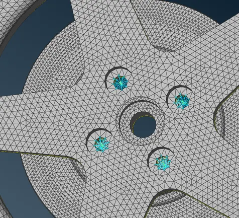
final view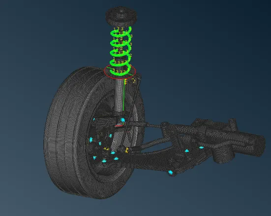
after mirroring ;the final model
LEARNING OUTCOMES:
-
geometry cleanup and extract midsurface for sheet metal components
-
how to define a volume and perform Solid Meshing
-
to perform meshing and obtain good quality mesh and proper mesh flow
-
different types of connections and how to implement connection
CONCLUSION:The given components were meshed by choosing the right element type and the mesh quality was also ensured by following the given quality criteria.
Thanks,
VishalModel :
https://drive.google.com/file/d/1l54aMBy0kRP_l2m7qpU9OcgJLOHmC-L6/view?usp=sharing