Project - 2 - Meshing on the suspension Assembly
Aim:
In this project check the geomtry errors and mesh the geomtry and take volue of the given rear suspension.
Given data:
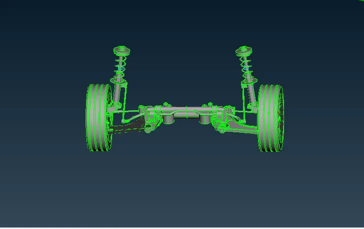
Geometry
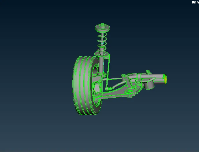
Given quality criteria:
Quality criteria for Surface Meshing of Non Uniform thickness components other than Tyre and Rim (Element type: Tria) :
|
S.No |
Quality Criteria |
Value |
|
1 |
Target/Average length |
4 |
|
2 |
Minimum Length |
2 |
|
3 |
Maximum Length |
6 |
|
4 |
Skewness |
45 |
Quality Criteria for Volume meshing of all Non Uniform thickness components (Element type: Tetra Elements):
|
S.No |
Quality Criteria |
Value |
|
1 |
Tet-collapse |
0.2 |
Quality criteria for Mid surfacing of Uniform thickness part which has thickness less than 5 mm (Element type: Mixed elements) :
|
S.No |
Quality Criteria |
Value |
|
1 |
Target/Average length |
4 |
|
2 |
Minimum Length |
2 |
|
3 |
Maximum Length |
6 |
|
4 |
Aspect |
3 |
|
5 |
Warpage |
15 |
|
6 |
Skewness |
45 |
|
7 |
Jacobian |
0.7 |
|
8 |
Minimum Quad Angle |
45 |
|
9 |
Maximum Quad Angle |
135 |
|
10 |
Minimum Tria Angle |
30 |
|
11 |
Maximum Tria Angle |
120 |
Procedure:
¬ Import the geometry , check and clean up geometry and clear the errors.
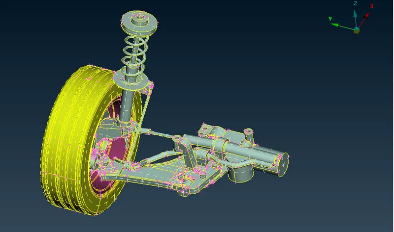
¬ Check the geometry eroors
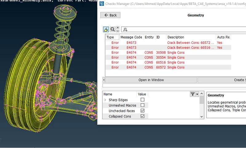
¬ Clear all errors select the errors and right click select fix option its done.
Meshing:
¬ Going to mesh the tyre.
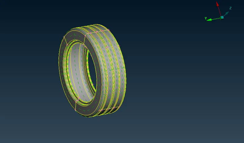
¬ Separted the type part start meshing.
¬ Go to model browser add the tyre part .
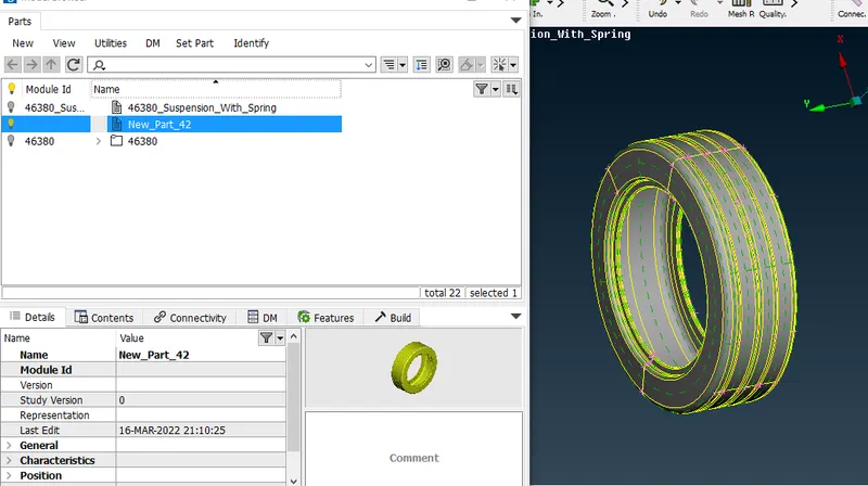
¬ Then go to batch mesh add new meshing scenario add the tyre part.
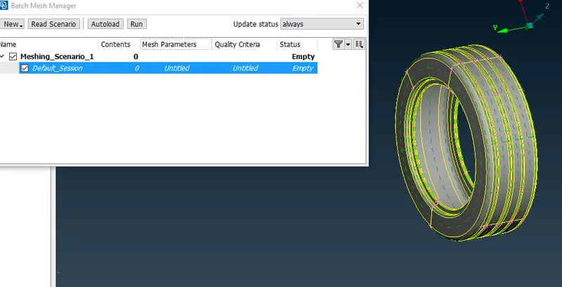
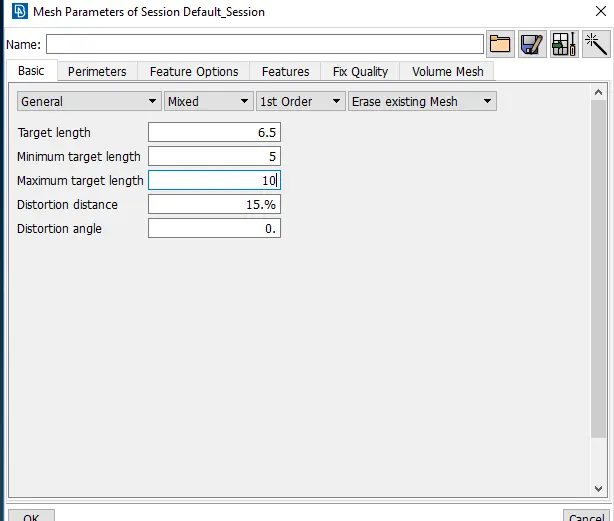
¬ Now assign the mesh parameter>
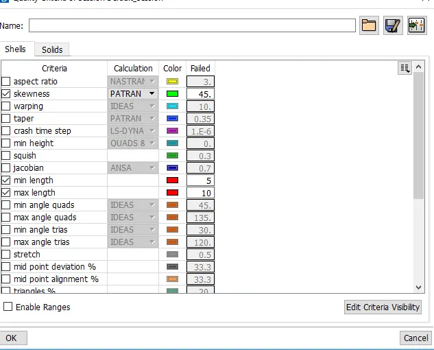
¬Then asssign the quality parameter as given in question.
¬ Now click the Run button to generate the mesh.
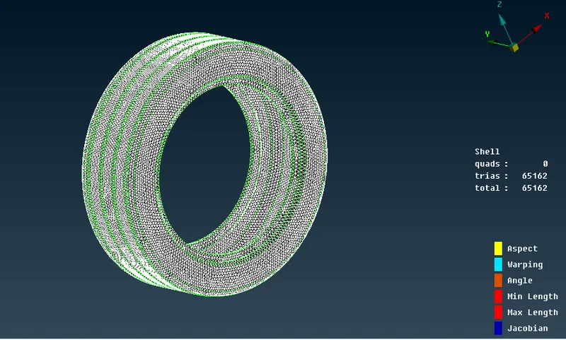
¬ The whole components meshed using tria elements.
¬ clear all the quality issues.
Volume Mesh:
¬ Before volume mesh go to assign quality criteria for volume.
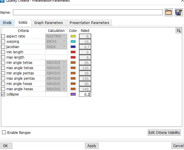
¬ After assign the quality go to start the tetra mesh.
¬ In tetra mesh first define the components to be volume.
¬ This id done by volume mesh- volume - define -manual option.
¬ Then select the components and defined the part.
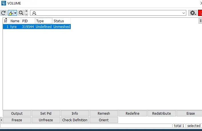
¬ After mesh the components create the PID for solid.
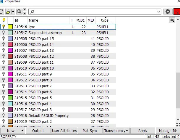
¬ volume mesh created for tyre part.
¬ similar to do for all the parts as well.
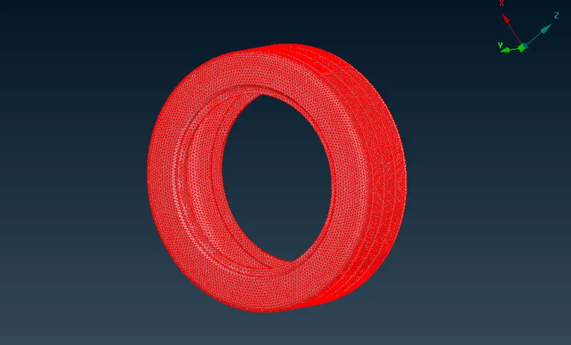
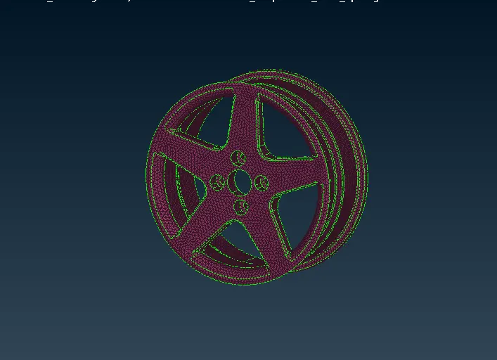
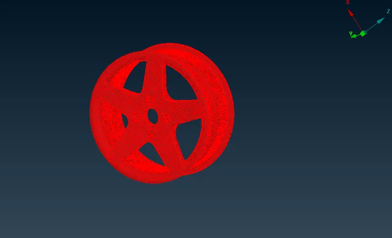
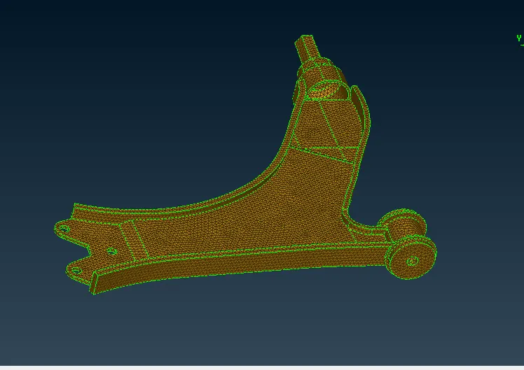
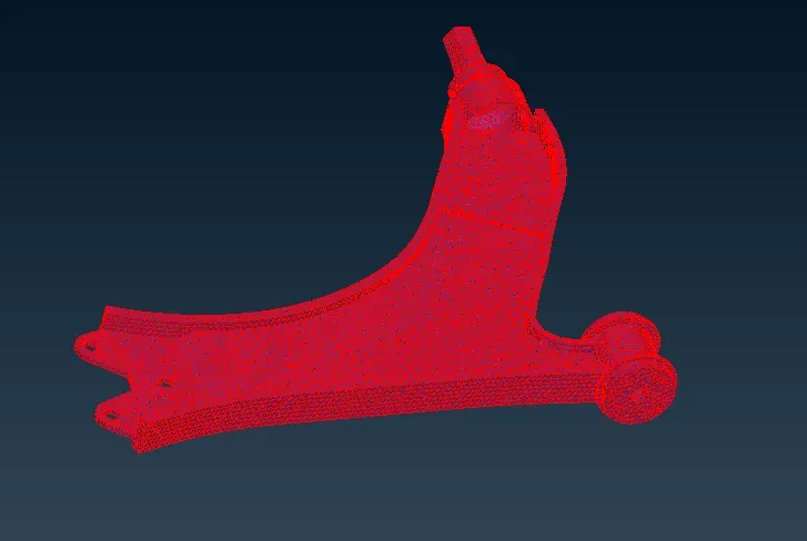
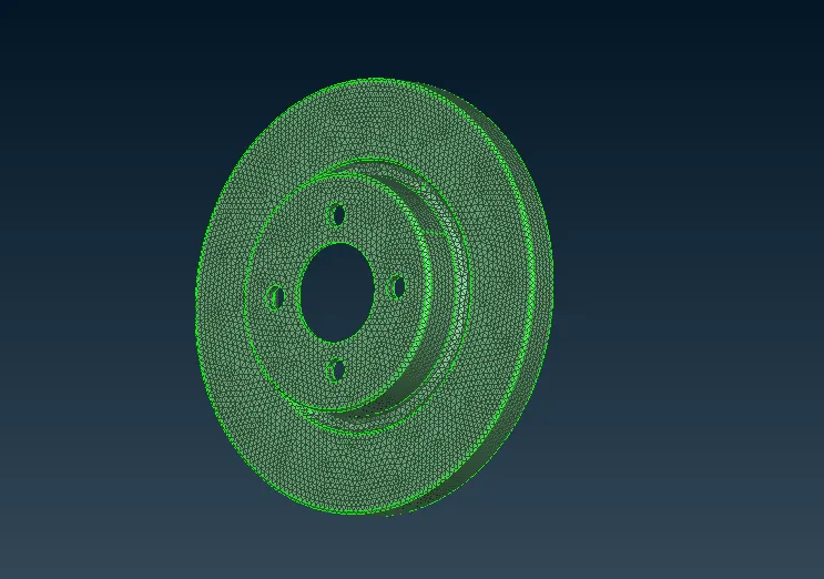
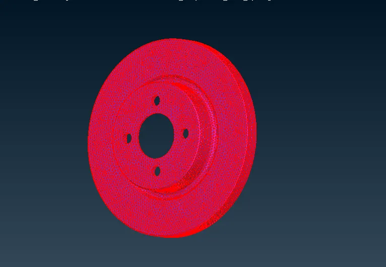
¬ create volume for all the non uniform parts in the components.
Mesh the uniform components:
¬In this model it has only two uniform components
¬ Now take midsurafce and meshed the components.
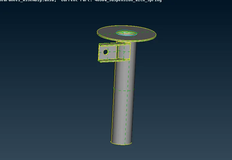
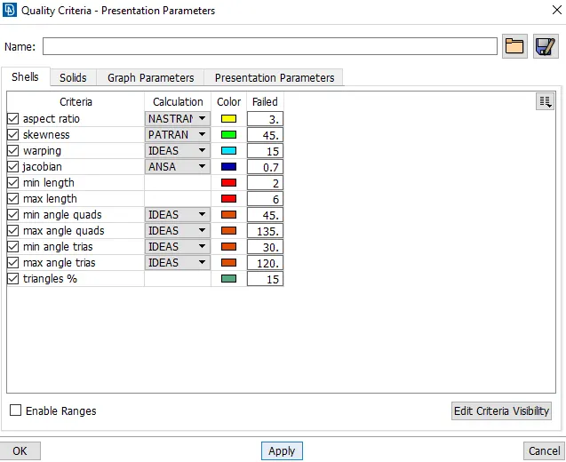
¬ Assign the quality criteria for uniform components.
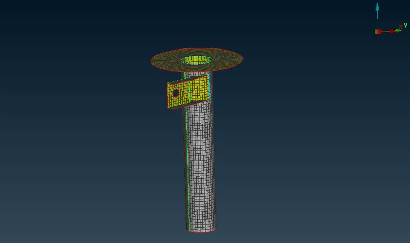
¬ after comple the meshing the components assign the thickness of the components.
1D meshing for spring:
¬ In spring type parts used 1d mesh method to slove this.
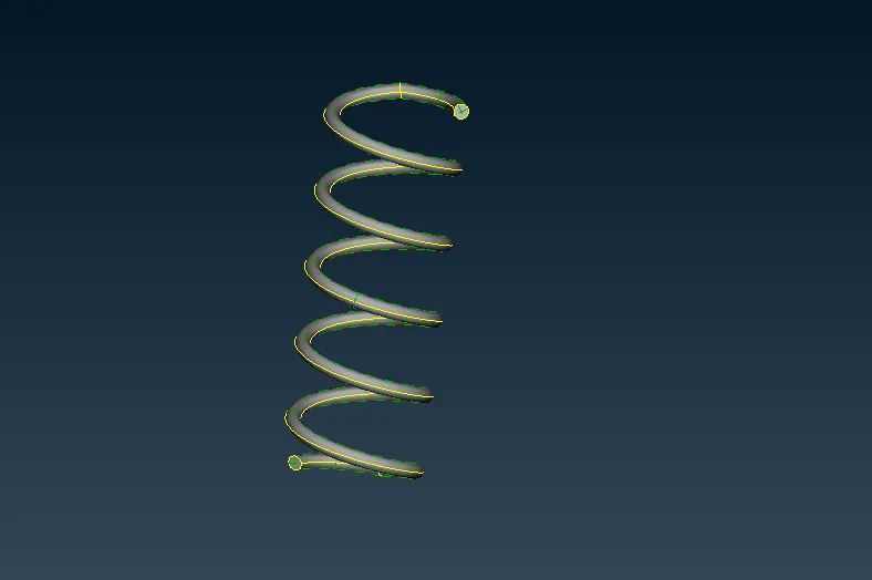
¬ First go to Topo - curve- middle used to cretae the curve full compnents of the spring.
¬Then created curve have multiple curve converted into single curve.
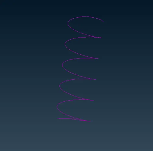
¬ Then create 3d point go to topo-point-oncog-edge .
¬ 1d spring create using nastran deck -elements -cbar .
¬ Open windows select area choose the spring radius then it converted into 1d part
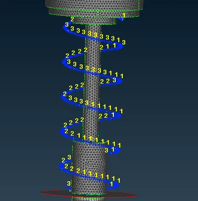
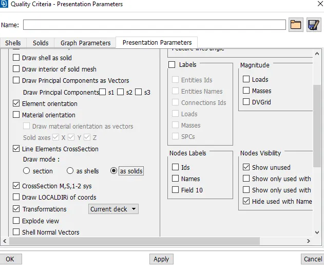
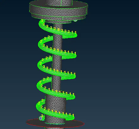
¬ after created 1d part go to quality parameter-presentation parameters- line element crossection
¬ choose as solid.
Connection:
¬ Now going to conncect various part.
¬ Connecting the Rim disc brake assemble are connected through the bolt connection method.
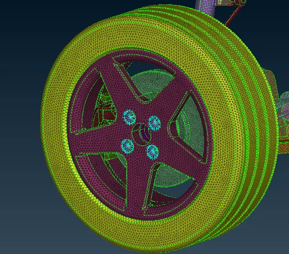
¬ Like wise other parts where need bolt connection required its done by using the RBE2 method.
¬ Now go to Nastran deck -RBE2- many nodes and select the area and rightbody connection its done.
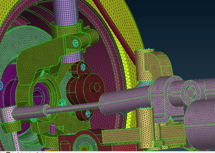
¬ In some required seam weld connection.
¬First create line curve using FEAt2curve option in Topo.
¬ Then using connection manager select the curve , open window go to overlap shell joint.
¬ then select p1 and p2 value its done.
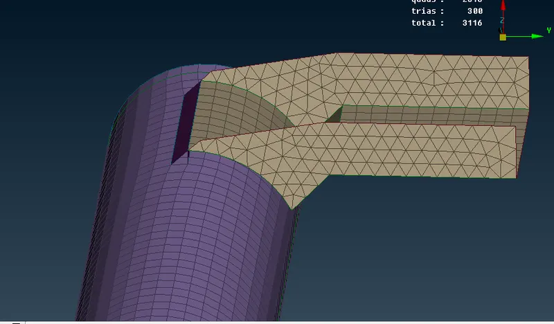
¬ seam weld joint its done.
¬ Then where ever connection needed it would be completed through rigit joint method.
Symetry :
¬ Intially give half portion of the rear assembly and done all the works.
¬ Using symetry option to create another half as slimilar to this components.
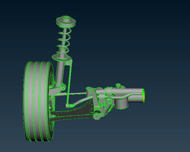
¬ Go to utlities- tranform- select copy option and the entites go symetry.
¬ choose the 3 point method.
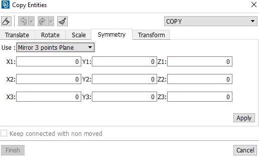
¬ Select the 3 points where it to symetry .
Learning outcomes:
¬ Check geometry and clear all the errors.
¬ learn to take mid surface of components .
¬ lear to identify the uniform and non uniform components.
¬ learn to use batch mesh method.
¬ lwearn to create the volume tetra mesh.
¬learn to create weld method.
¬learn to give rigit connection toi the components.
Conclusion:
¬ Given Rear assembly should be clear the geomtry , midsurface created and tetra mesh it all compeleted as the given value.
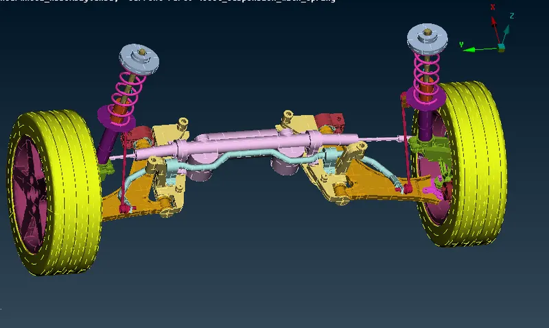
Geometry:
¬ This image fully geometry .
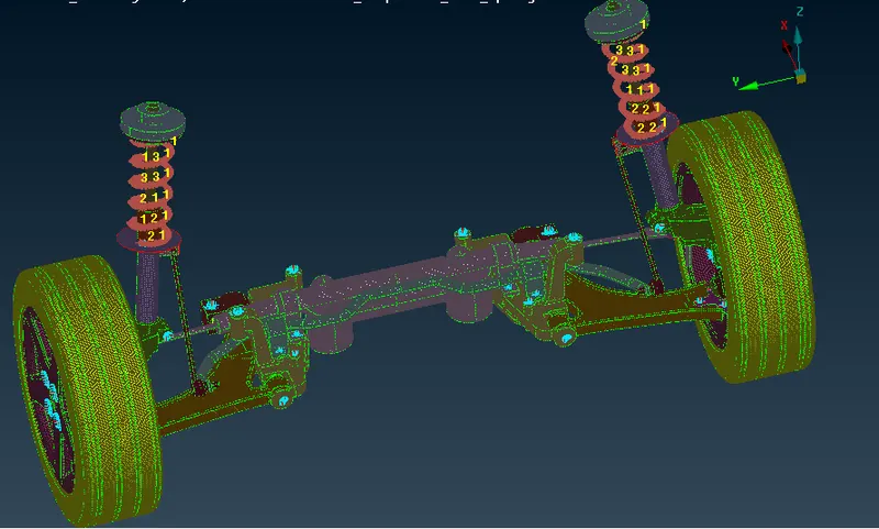
FEM:
¬This image is Finite element method
Volume:
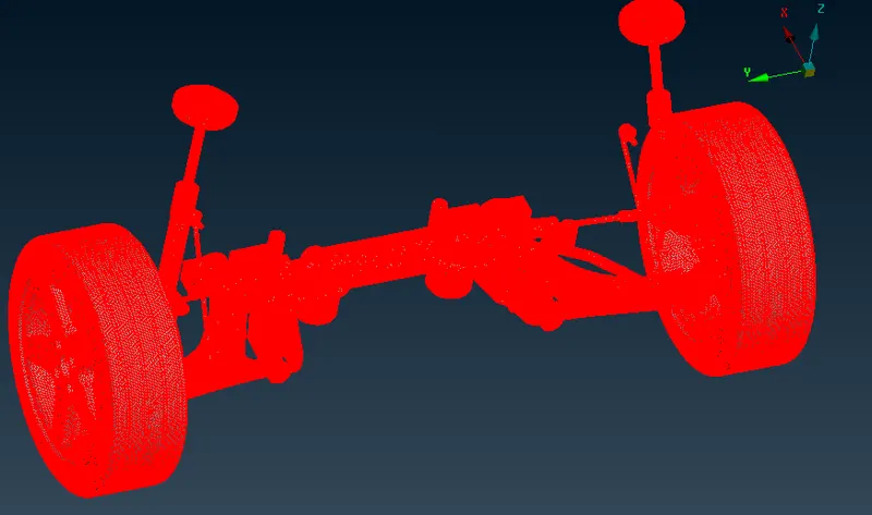
¬ This image is volume method