Project - 2 - Meshing on the suspension Assembly
PROJECT 2- MESHING ON SUSPENSION ASSEMBLY
AIM: To check for geometrical errors and mesh the given suspension assembly model and also, satisfy the given quality criteria.
Quality Criteria for Surface Meshing of Tyre and Rim (Element type: Tria) :
|
S.No |
Quality Criteria |
Value |
|
1 |
Target/Average length |
6.5 |
|
2 |
Minimum Length |
5 |
|
3 |
Maximum Length |
10 |
|
4 |
Skewness |
45 |
Quality criteria for Surface Meshing of Non Uniform thickness components other than Tyre and Rim (Element type: Tria) :
|
S.No |
Quality Criteria |
Value |
|
1 |
Target/Average length |
4 |
|
2 |
Minimum Length |
2 |
|
3 |
Maximum Length |
6 |
|
4 |
Skewness |
45 |
Quality Criteria for Volume meshing of all Non Uniform thickness components (Element type: Tetra Elements):
|
S.No |
Quality Criteria |
Value |
|
1 |
Tet-collapse |
0.2 |
Quality criteria for Mid surfacing of Uniform thickness part which has thickness less than 5 mm (Element type: Mixed elements) :
|
S.No |
Quality Criteria |
Value |
|
1 |
Target/Average length |
4 |
|
2 |
Minimum Length |
2 |
|
3 |
Maximum Length |
6 |
|
4 |
Aspect |
3 |
|
5 |
Warpage |
15 |
|
6 |
Skewness |
45 |
|
7 |
Jacobian |
0.7 |
|
8 |
Minimum Quad Angle |
45 |
|
9 |
Maximum Quad Angle |
135 |
|
10 |
Minimum Tria Angle |
30 |
|
11 |
Maximum Tria Angle |
120 |
PROCEDURE:
1) Import the given model.
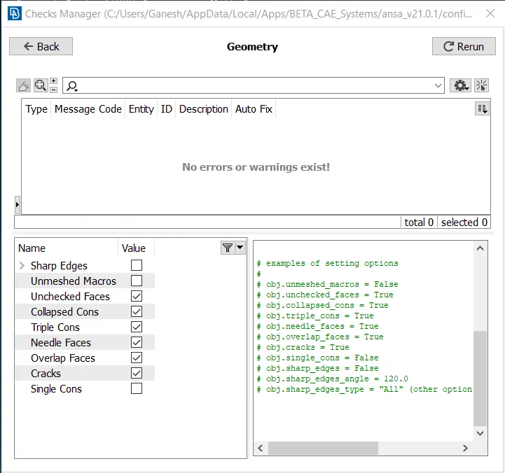
2) Check for geometrical errors. Errors are corrected using the auto fix option from the checks manager or manually using topo tools.
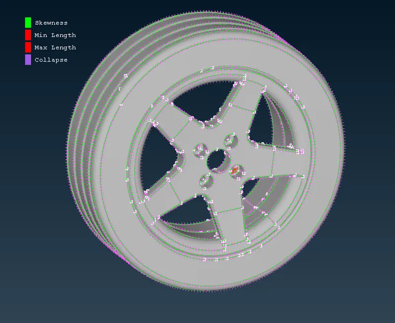
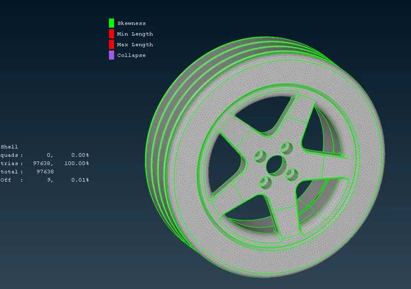
3) For tyre and rims we use the given quality criteria and mesh parameters to create a appropriate mesh. Some elements fail due to complexity of geometry but it can be accepted as the off elements are just 0.01% of all the elements.
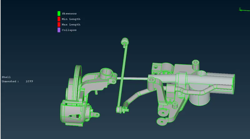
4) For other parts we use the given criteria and mesh parameters and mesh the components separately using the Best mesh tool and spotmesh tool respectively. Here too some elements fail the quality criteria due to complexity of geometry.
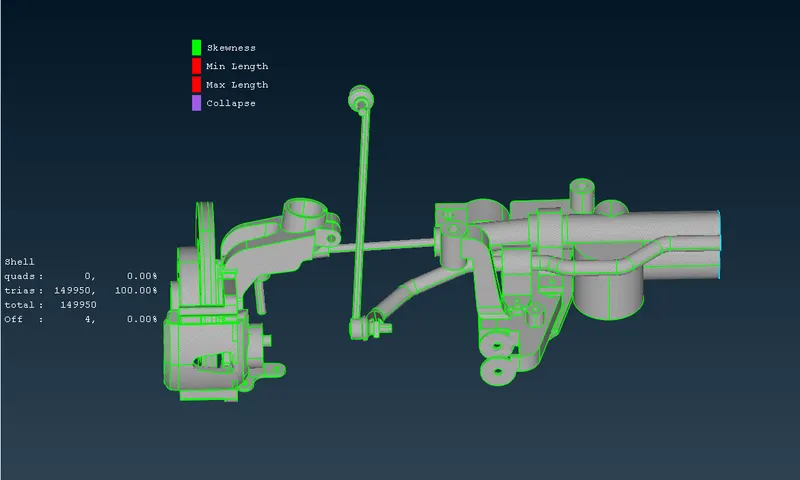
5) Parts which have uniform thickness are meshed by extracting a mid surface and then meshing the mid surface using the given meshing parameters and quality criteria.
6) In this case midsurface tool with casting option was used to create a meshed mid surface.
7) Some components of the strut rod assembly were meshed using the midsurface with casting option. And the components were meshed using trias using given quality criteria for the tria meshing.
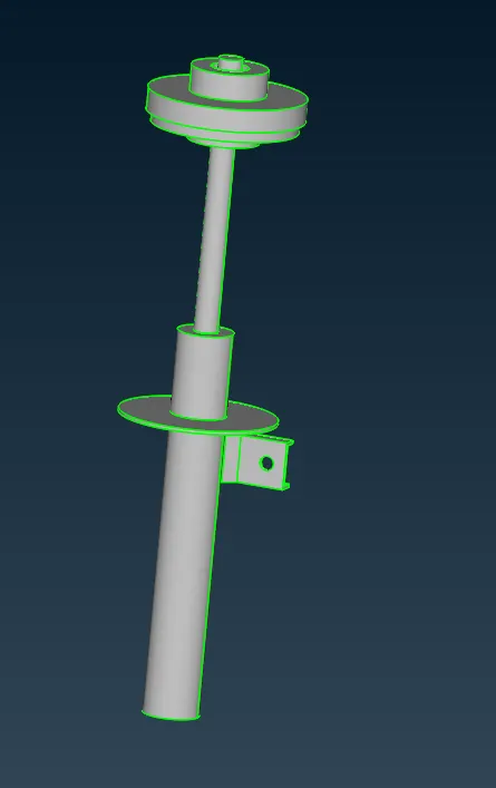
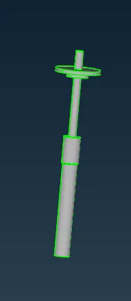
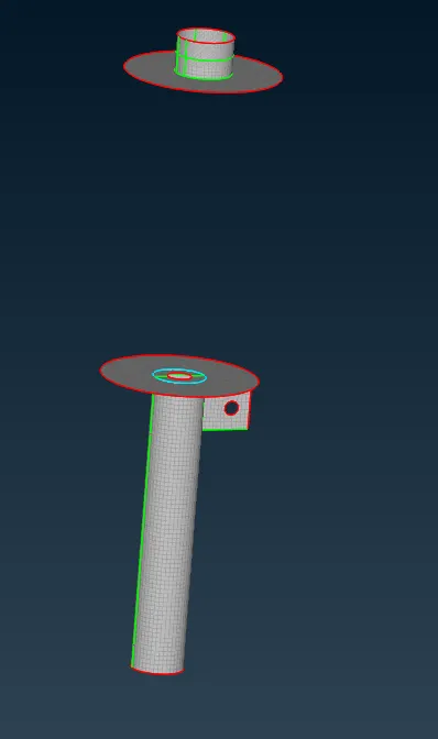
8) The subframe of the suspension assembly was also meshed using the midsurface with casting option.
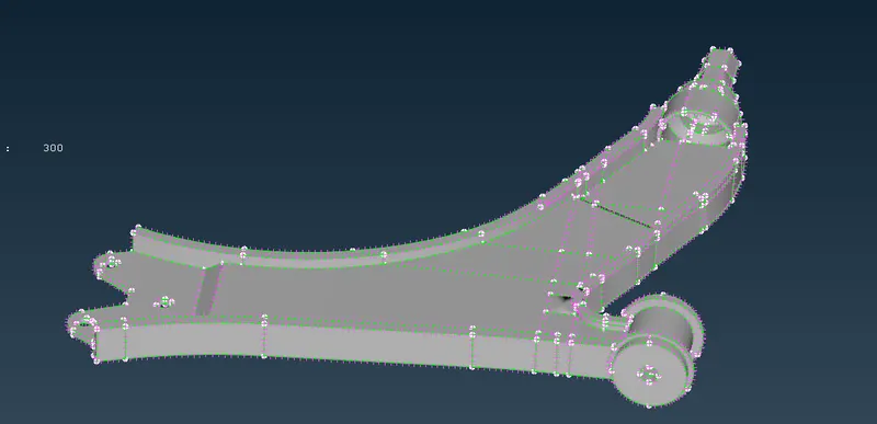
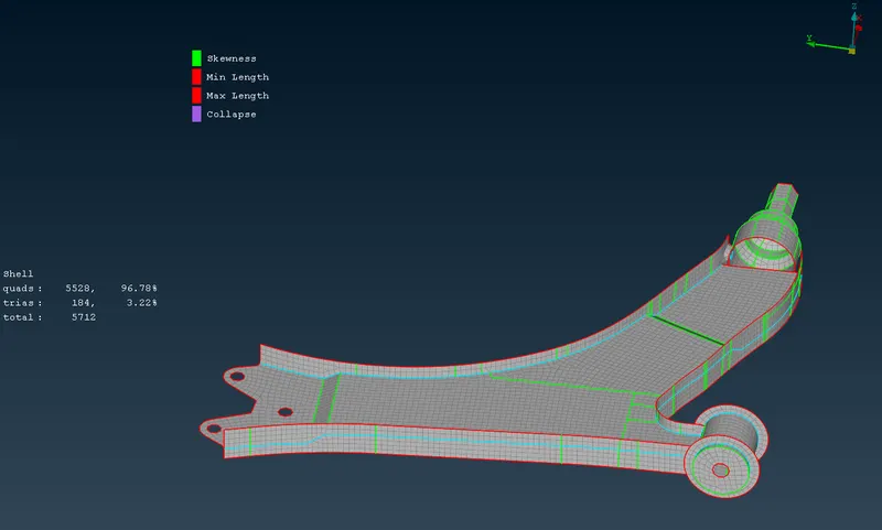
9) For all the trias created we create volumes to create a tetra mesh. Volumes are created by using the define tool with manual selection for each component. The tet collapse criteria was set to 0.2.
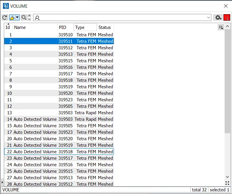
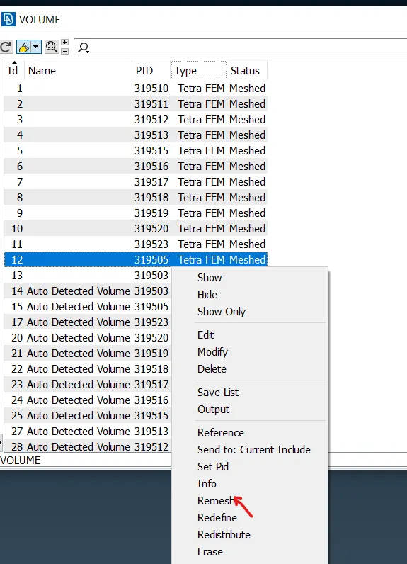
10) These volumes were then converted into tetra mesh by right clicking each volume and then the remesh option with Tetra FEM was selected to get good quality solid mesh.
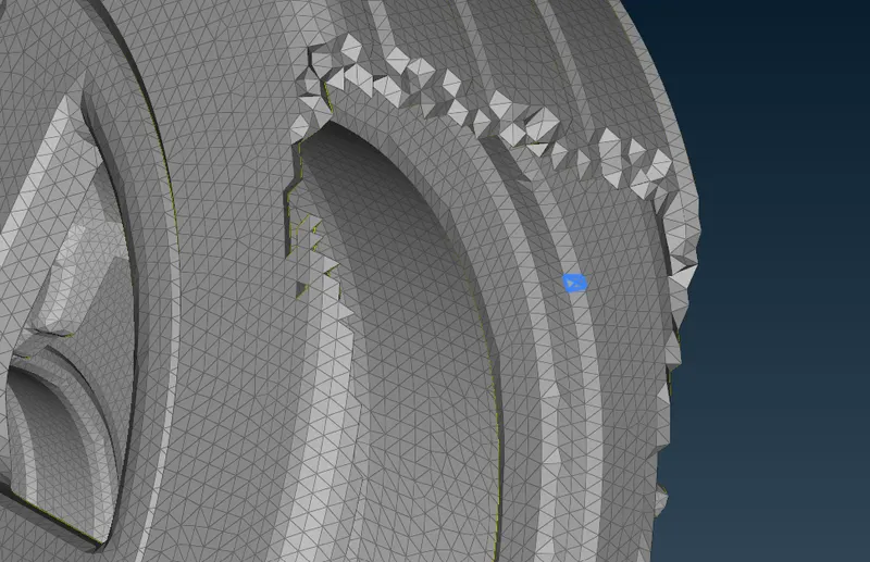
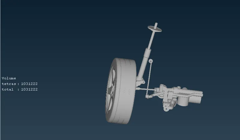
11) A tetra mesh for all the required components is created with satisfying tet collapse criteria. If any tetra element was failing tet collapse criteria, fix quality option or the element was manually nmodified with suitable height using the move option. Below shown image is a section of tetra created. Also the whole tetra meshed components are shown below section tetra mesh.
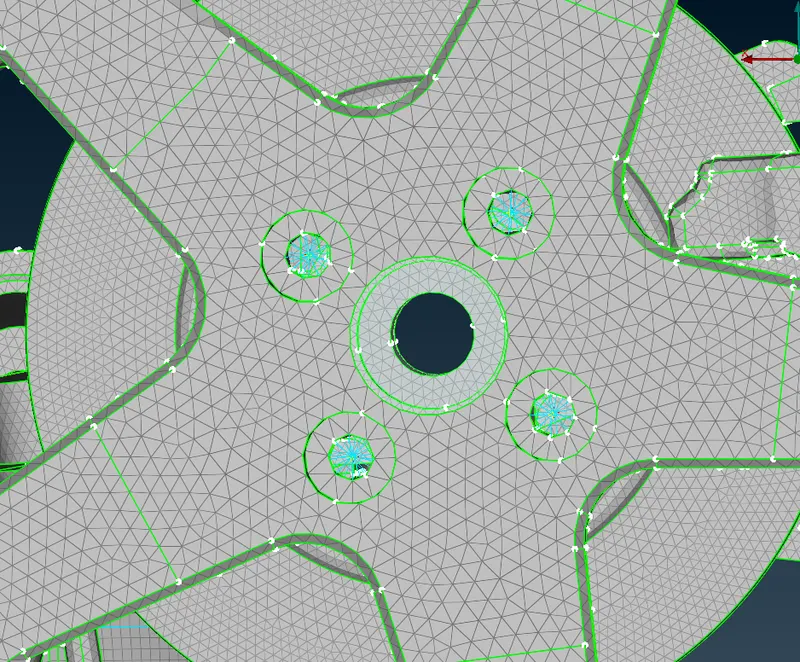
12) After completing the meshing process, we create connections. A bolt connection is created using rbe2 elements with multiple nodes for the holes and then the centroids are connected using the rbe2 elements using two nodes option.
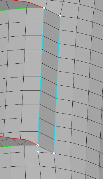
13) Seam weld connection are used to create a overlap shell connection in strut rod assembly. To create a seam line, first a curve is created using fea2curve option then this curve is then converted into a seam line. Then using connection manager the two components are connected.
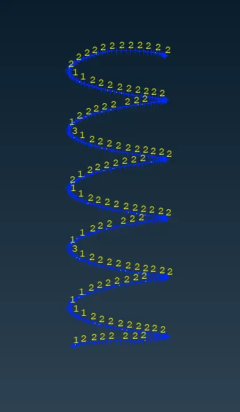
14) For the spring component first a curve is created using middle curve option. Then the curves are connected using connect option. Then the curve is converted into CBAR element using the CBAR option in NASTRAN deck. Then a property is created where a crossection is given according to parent model to the spring. The spring is thus converted into FEA element.
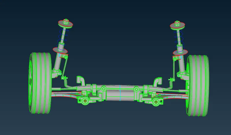
15) After creation of all the elements, the whole mesh is then mirrored using the transform tool.In the transform tool symmetry option with 3 point plane is selected to mirror the whole mesh.
CONCLUSION AND LEARNING OUTCOME:
- Tetra mesh and shell mesh both are created.
- Connections are deployed wherever required.
- Use of different options in all the Topo, shell, volume mesh and Nastran Deck section is understood.
- Mirroring operation is also performed using the transform tool.