Week 4- Challenge
WEEK 4 CHALLENGE
AIM:
- To create midsurfaces of given component and meshing the component with element size of 5.
- Create bar, rod and beam element and also apply mass and spring elements.
PROCEDURE:
1] Import the geometry from given IGES file.
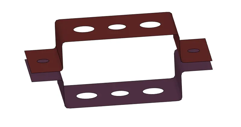
2] After importing the geometry create midsurfaces 1 and 2 using midsurface panel from the Geometry section.
3] Select individual brackets to create two different midsurfaces.
4] The extracted midsurfaces look like this.
5] Assign material(Steel, MAT1) and properties(crossection=2.5 and 3) to these midsurfaces by creating properties and material in the model browser.
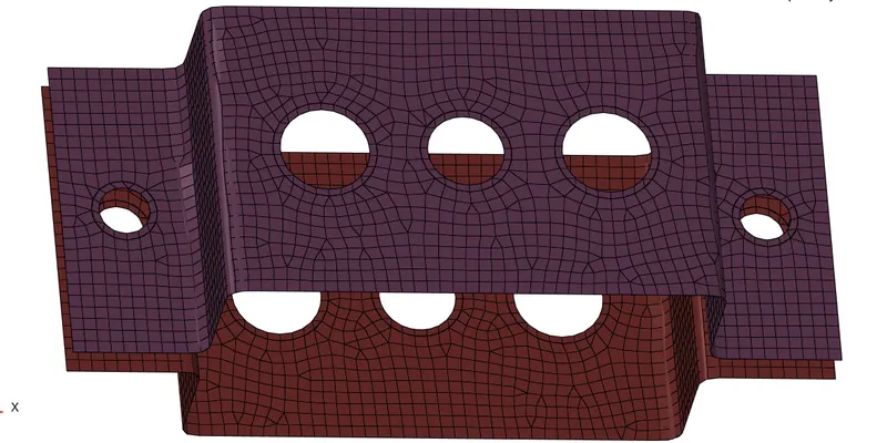
6] We create a washer split of 3 mm to increase the quality of mesh near the holes.
7] Mesh these midsurfaces by using automesh panel in 2D section. The mesh is of mixed type with element size of 5 mm.
8] We then create RBE2 elements using rigids panel in 1D section. We constrain using dof1,dof2 and dof3 which is used to constrain translation in X, Y and Z axis.
9] We then create RBE3 elements using RBE3 panel in 1D section. For constraining all DOFs selecting all the dofs in this panel and for constraining in X and Y we select all dofs except dof3 and dof6.
10] We then create crossections for the connecting elements such as rod, bar and beams using the hyperbeam panel in 1D section. Here we need standard section of thin walled box, I section and Cross-section X section so we select the standard section in hyperbeam panel and proceed to create the cross sections of required dimensions.
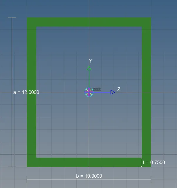
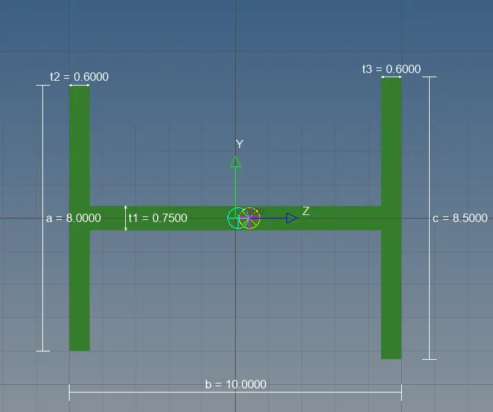
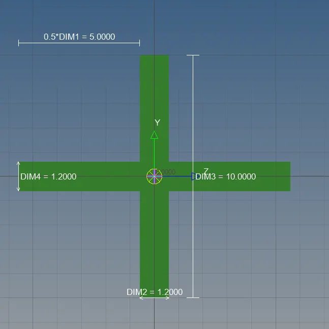
11] After creating cross sections, we again create properties to assign cross-section to rod, beam and bar element.
12] Create rod element using rods panel in 1D element and assign properties by selecting the rod property and select element type CROD.
13]Similarly we create beam and bar elements using the bars panel in 1D elements.
14] We now create masses by using RBE2 link and using the masses panel in 1D elements, we apply a magnitude of 10.
15] We also create a spring element at the ends by using spring panel in 1D elements.
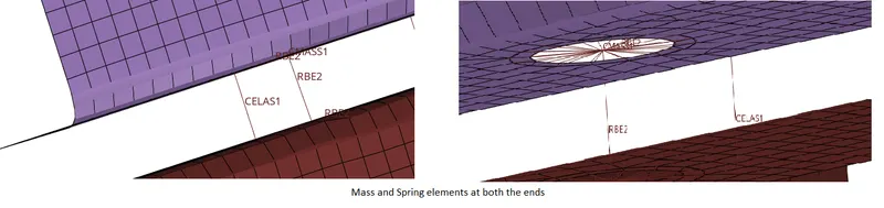
16] We have applied all the conditions on the given component.
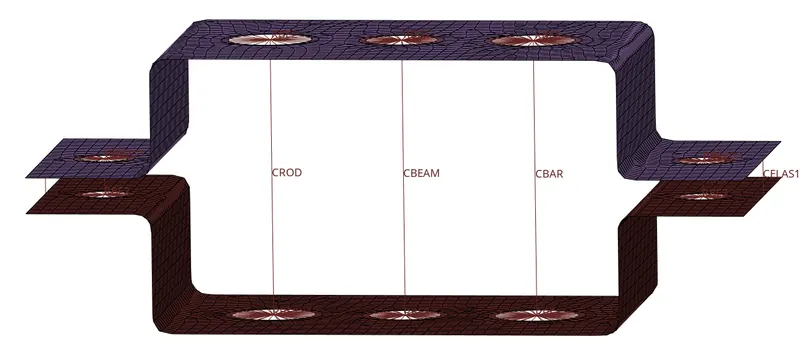
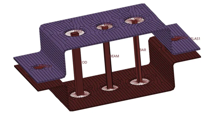
17] To get a good visual details such as cross-section of rod, beams and bar, and also the thickness of midsurface we select the commands " 1D Detailed Element Representation" and "2D Detailed Element Representation" .
CONCLUSION:
- From this assignment we get familiarised with midsurfaces.
- We also got to know how to use RBE2, RBE3 elements along with rods,bars and beam elements in Hypermesh.
- We also got to know to create cross-sections using hyperbeam and, apply masses and spring elements.