Project - 2 - Meshing on the suspension Assembly
AIM
- To carry out 2D shell mesh on components with thickness less than 5mm and then assign appropriate thickness.
- To carry out volume mesh on components with thickness greater than 5mm.
- To validate the mesh generated based on the given quality criteria.
- To integrate the model with necessary connections.
PROCEDURE
- To begin with the whole component is is checked for any geometrical irregularities as shown in the images below. The errors if found are rectified.
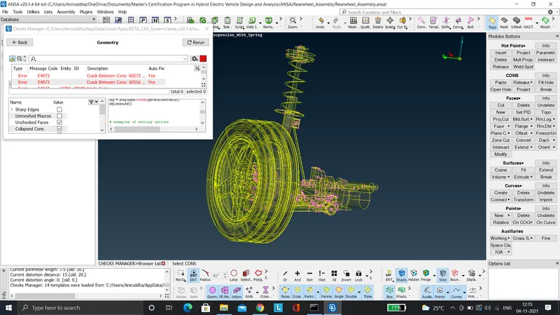
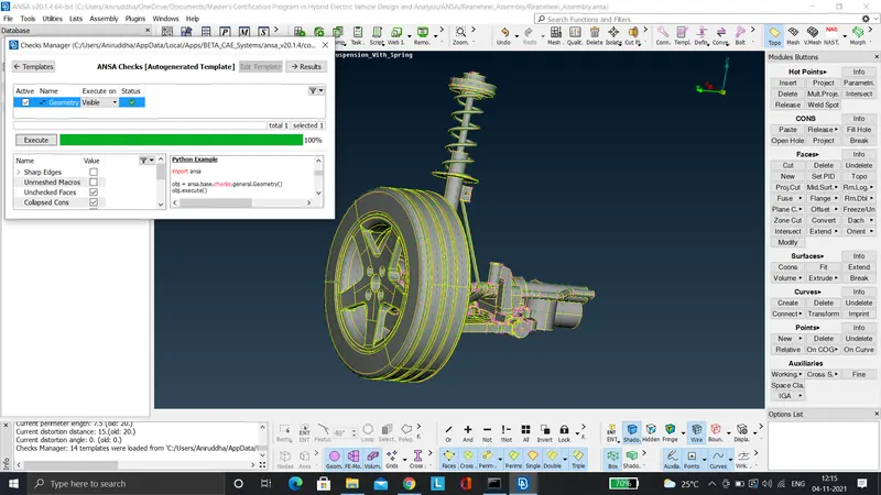
- The wheel and rim components have to be volume meshed, since their thickness is way beyond 5mm. But first it is required to assign the quality criteria and mesh parameters as shown in the images below.
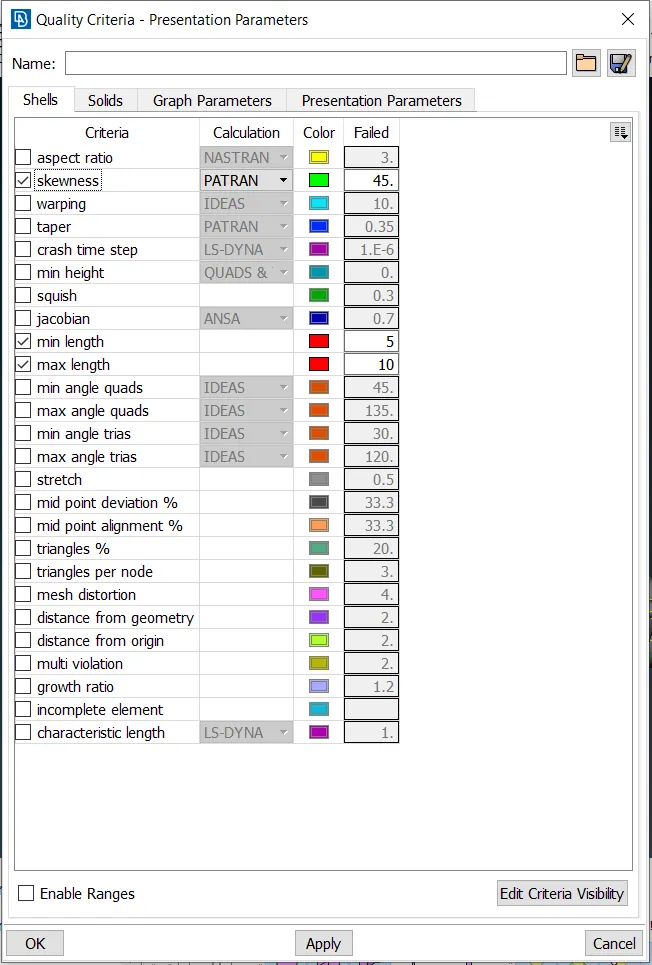
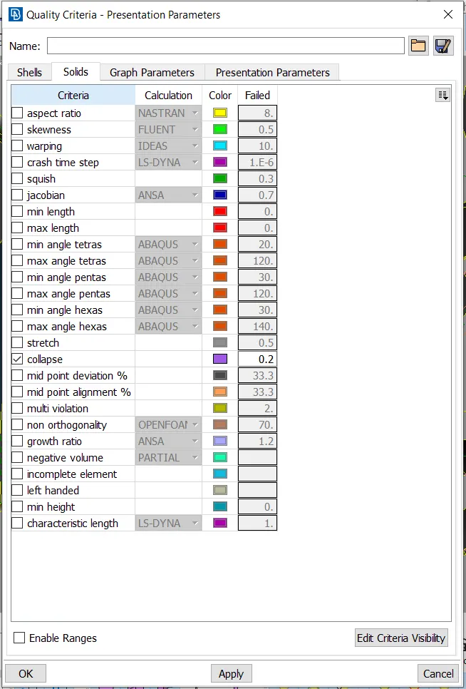
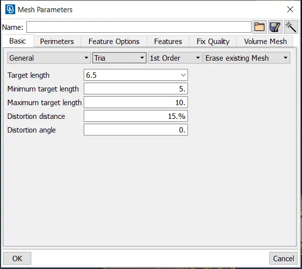
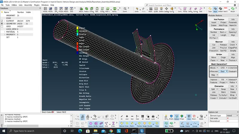
- We start with the 2D shell meshing process by using the ortho tria elements for the curved features, since they offer better feature capturing and connectivity along curved edges. But the one drawback of meshing with ortho tria elements is that the processing time increases by many folds.
- The 'Best Mesh' tool is used for generating the mesh. The mesh generated, if not satisfactory or having any distortions can be rectified by using the 'Reconstruct' Tool.
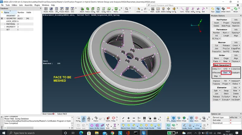
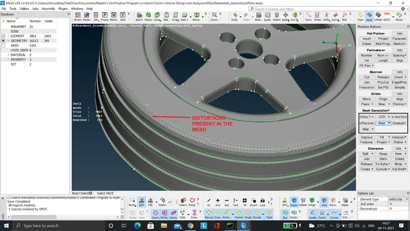
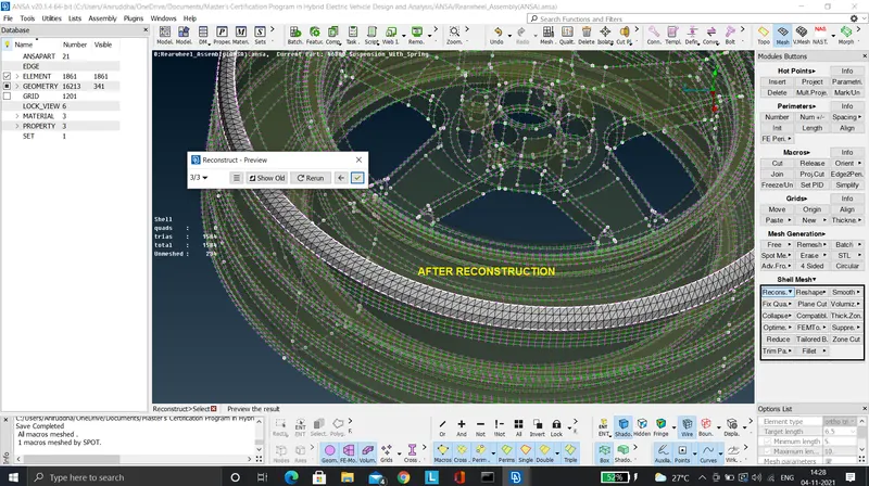
- Whereas the flat surfaces are meshed using trias and then reconstructed to rectify elements failing for quality criteria.
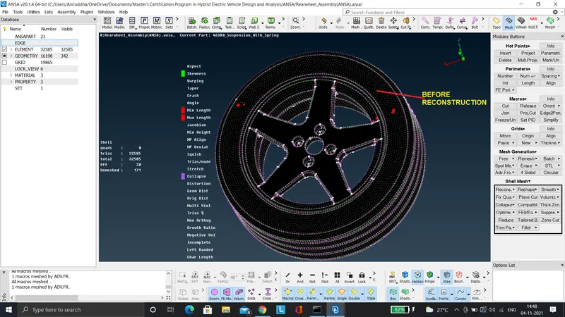
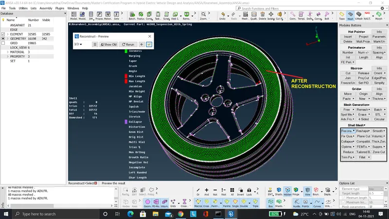
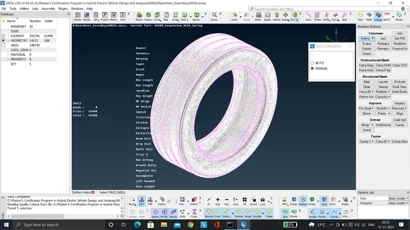
- Later on the volume is defined for the component using the 'Manual' option as shown in the image below.
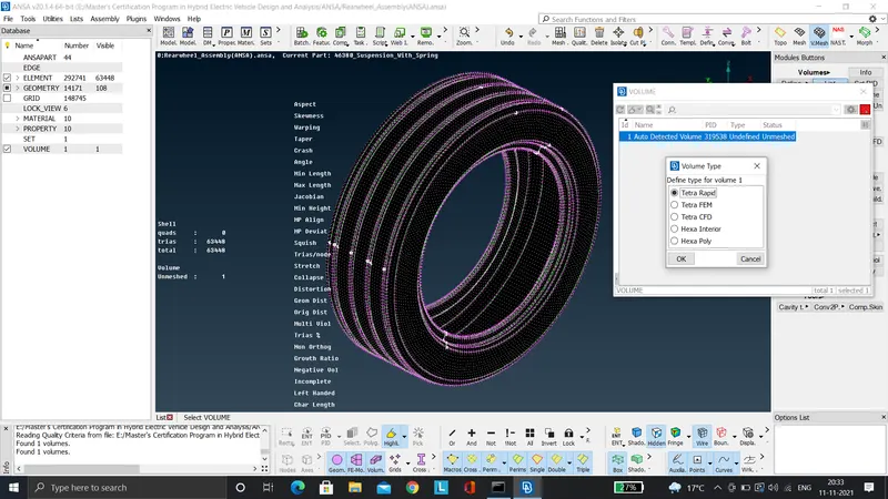
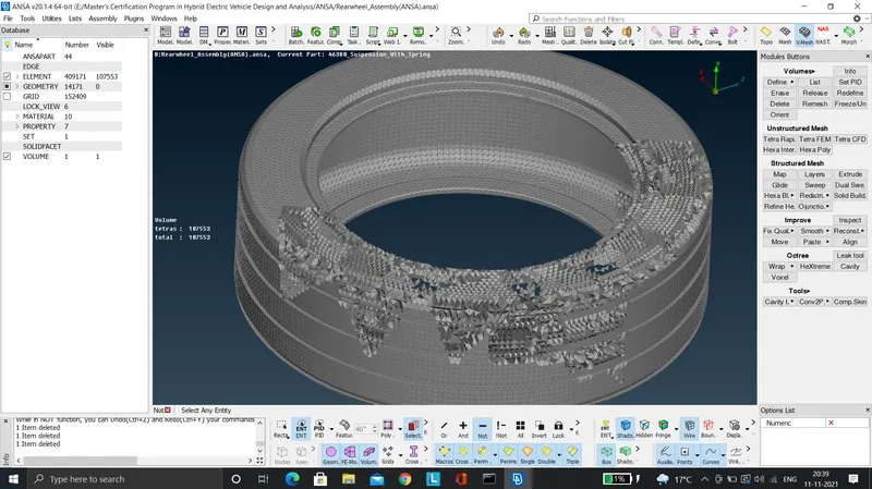
- Then the volume mesh is generated using the 'Tetra Rapid' option as shown in the images below.
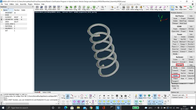
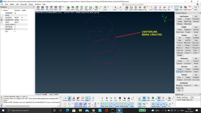
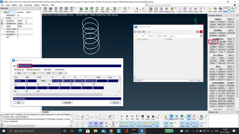
- Next the spring component is meshed using 1D bar elements. Using the 'Middle' tool under the 'Curves' panel in the 'Topo' module, a centerline to reperesent the spring is as shown below.
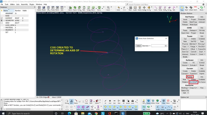
- Also the COG has to be defined to determine the axis of rotation as shown in the images below.
- Using the 'CBAR' tool under the 'NASTRAN' deck, the spring is modeled using 1D bar elements as shown below.
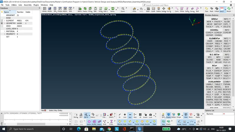
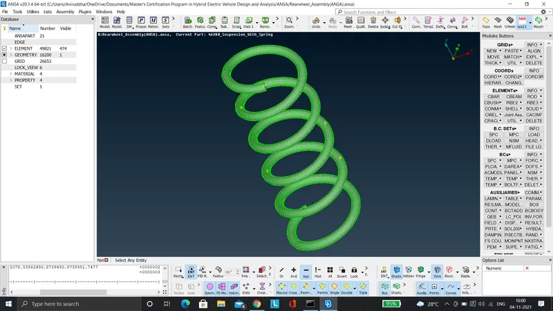
- The 1D bar mesh is visualised as a solid as shown in the image below.
- For the components with less than 5mm thickness, the midsurface is extracted using the 'Offset' tool and then meshed with 2D mixed elements as shown in the images below. The quality criteria and mesh parameters are defined beforehand.
- Finally connections have to established between the mating parts.
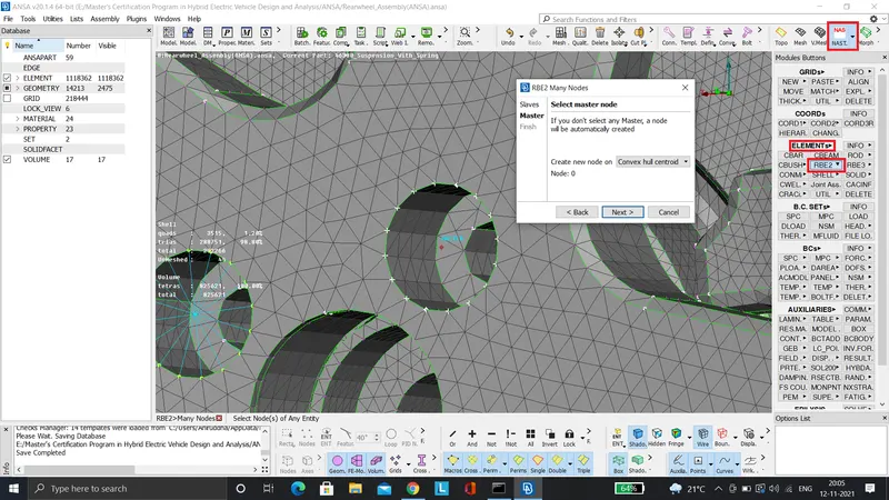
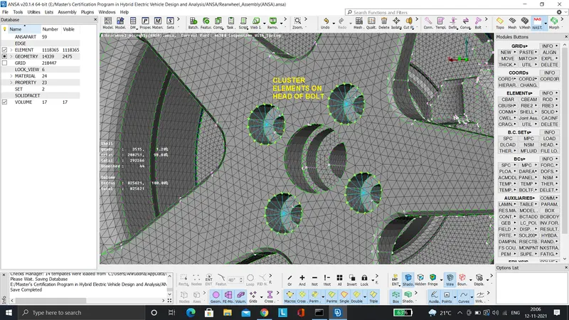
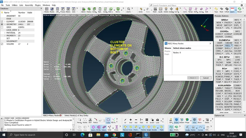
- The bolt is represented by using RBE2 elements as shown in the images below. The head and bottom of the bolt are represented by cluster RBE2 elements as shown in the images below.
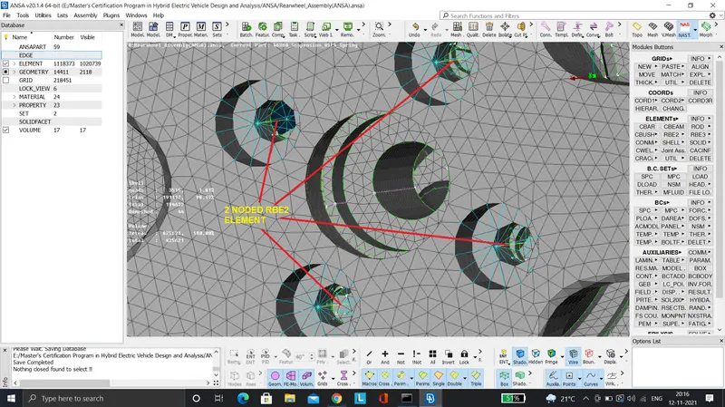
- Finally both clusters are joined using 2 noded RBE2 elements as shown in the images below.
- Seam weld is created between overlapping surfaces. At first the free edge is converted to curve using the 'Cons2Curve' tool under the 'Curves' panel of 'Topo' panel.
- The connection type is converted to 'Seam Line' as shown in the images below.
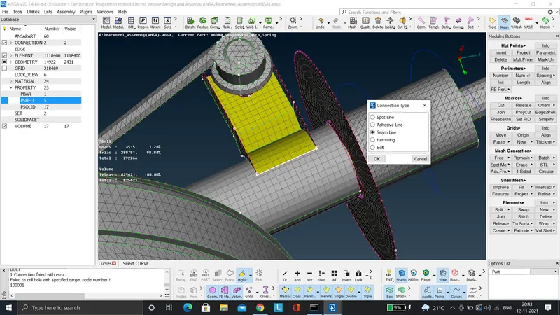
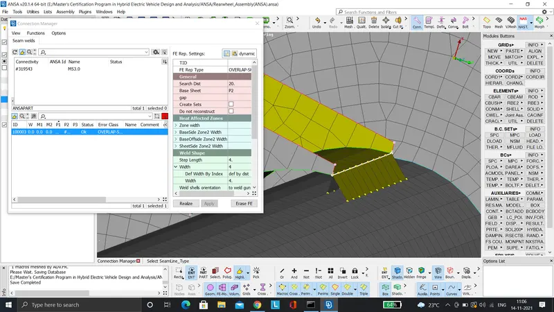
- Then using the 'Connection Manager' the seam weld is generated. First the P1 & P2 regions are selected accordingly.The FE Rep type is set to 'Overlap Shell' as shown in the images below. The search distance is set to 20. The step length and width are set to 4.
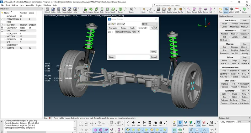
- Finally the 'Symmetry' tool is used reflect the components on to the other half as shown in the image below.
LEARNING OUTCOME
- The various tools concerned with geometry cleanup, midsurface extraction, mesh generation (2D shell & volume) & connections were learnt during the course of this project.
CONCLUSION
- The model of a rearwheel suspension assembly of a car has been meshed as per the given quality criteria and the necessary connections have been established.