Project - 2 - Meshing on the suspension Assembly
- AIM:
The main aim of the project is to mesh the suspention model according to the given quality criteria and to deploy the connection wherever required.
- QUALITY CRITERIA:
FOR TYRE AND RIM:
| S NO | QUALITY CRITERIA | VALUE |
| 1 | Target/Average length | 6.5 |
| 2 | Minimum length | 5 |
| 3 | Maximum length | 10 |
| 4 | Skewness | 45 |
| 5 | Tet collapse | 0.2 |
FOR OTHER COMPONENTS:
| S NO | QUALITY CRITERIA | VALUE |
| 1 | Target/Average length | 4 |
| 2 | Minimum length | 2 |
| 3 | Maximum length | 6 |
| 4 | Skewness | 45 |
| 5 | Tet collapse | 0.2 |
FOR MIDSURFACE:
| S NO | QUALITY CRITERIA | VALUE |
| 1 | Target/Average length | 4 |
| 2 | Minimum length | 2 |
| 3 | Maximum length | 6 |
| 4 | Skewness | 45 |
| 5 | Aspect | 3 |
| 6 | Warpage | 15 |
| 7 | Jacobian | 0.7 |
| 8 | Min quad angle | 45 |
| 9 | Max quad angle | 135 |
| 10 | Min Tria angle | 30 |
| 11 | Max Tria angle | 120 |
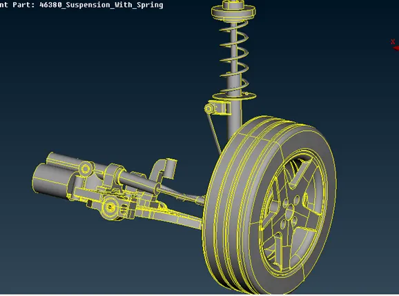
1.Extract the given suspenstion model to the ANSA envirnoment.
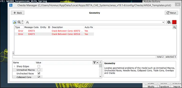
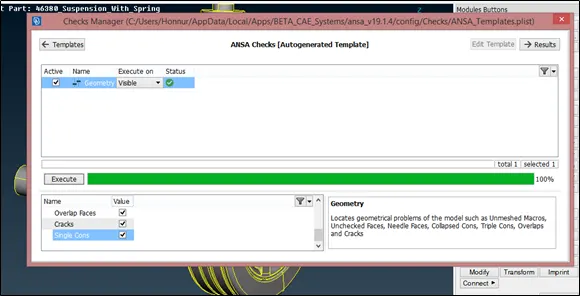
2.Check for the geometrical issue and fix the issue if any either manually of auto fix in checks manager
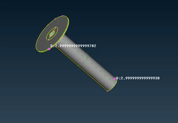
3.Measure the thickness of differerent parts and decide on which part what type of mesh to be deployed.As we observed the thickness is less then 5,take the mid surface and used mixed elements to mesh the mid surface or use auto mid option to take the same.
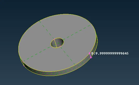
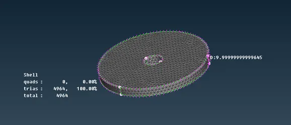
SPRING LOWER INSULATOR:
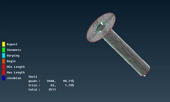
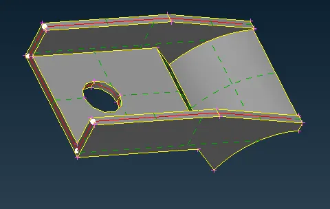
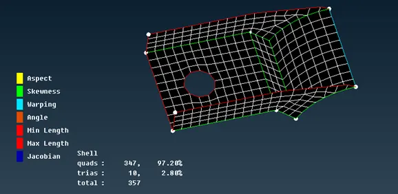
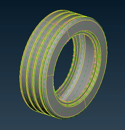
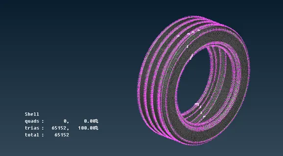
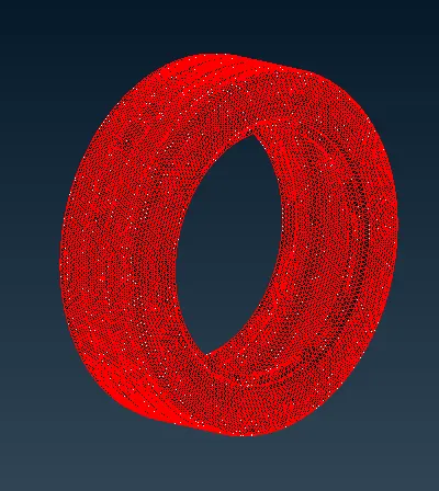
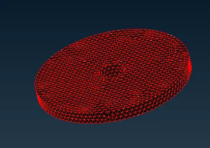
4.The tyre and rim part is meshed using tria elements,this can be get it done by using spot mesh option or by batch meshing and after deploying the mesh define volume in volume deck and use remesh with tetra rapid to obtain the volume mesh and solve for Tet collapse if any.
TIRE:
WHEEL RIM:
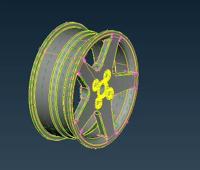
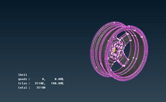
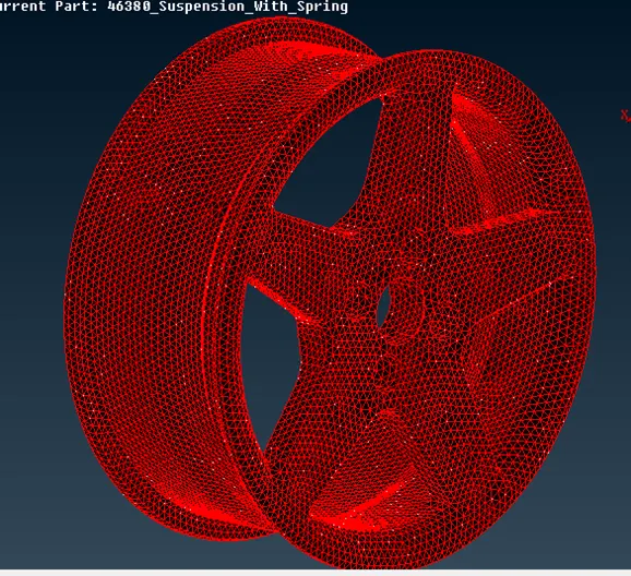
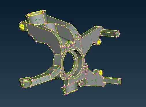
5.For other component approch will be same but make sure that the given quality criteria has been updated.
STRUT MOUNT:
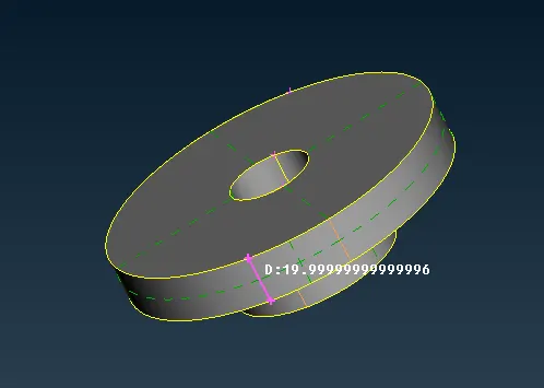
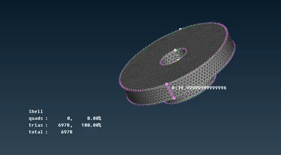
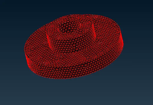
STEERING KNUCKLE:
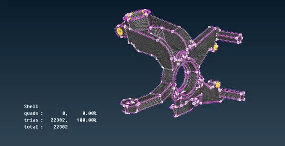
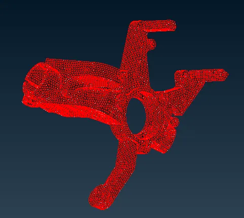
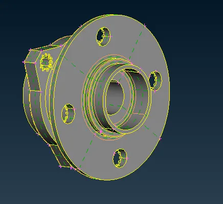
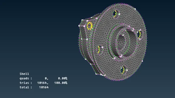
WHEEL HUB:
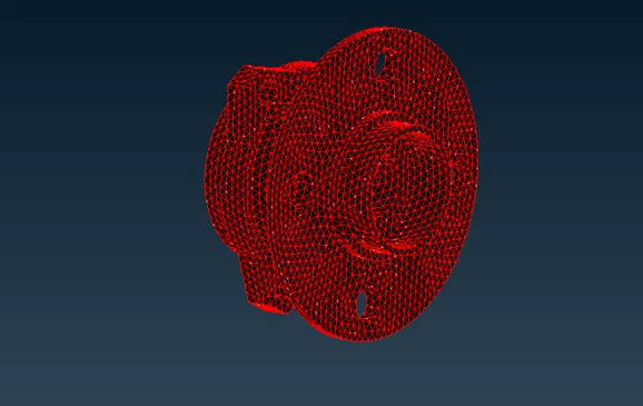
PENDULUM BAR:
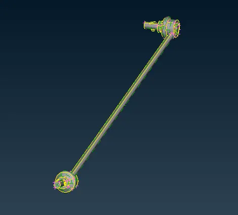
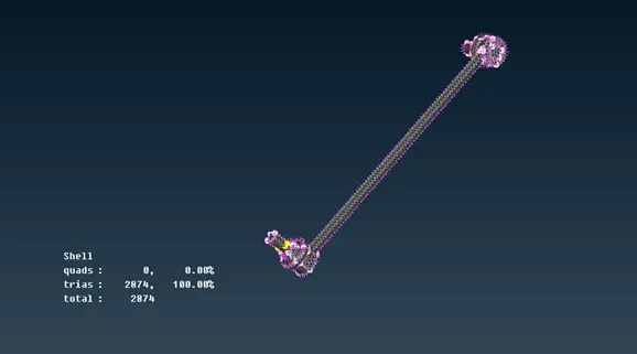
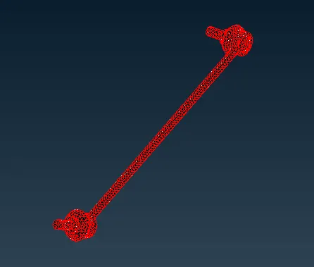
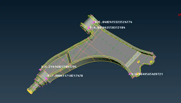
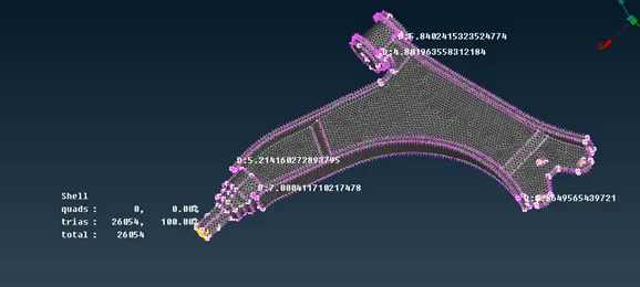
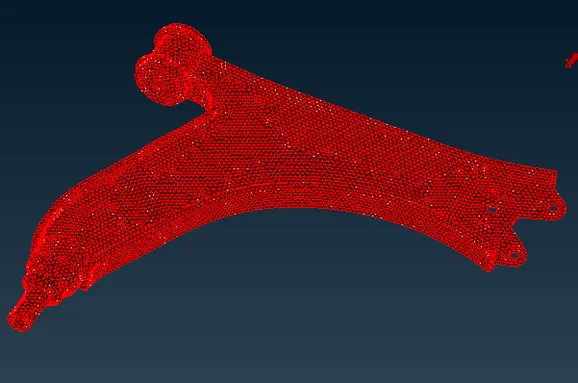
WISHBONE:
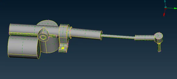
TIE ROD:
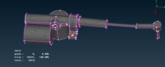
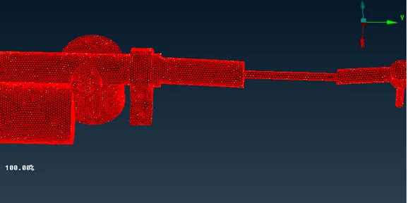
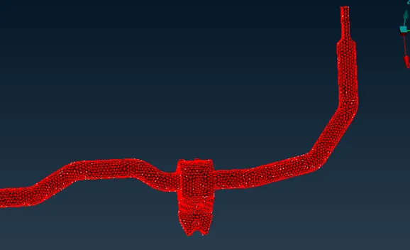
SWAY BAR:
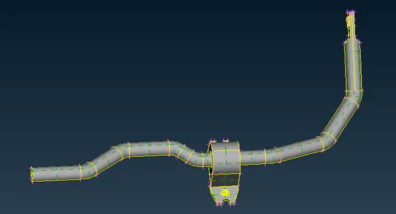
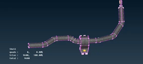
COIL SPRING:
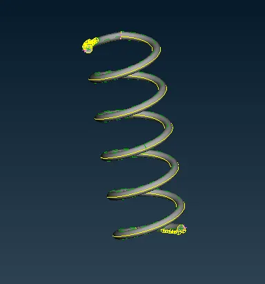
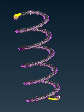
To model this spring use CBAR option in Nastran deck
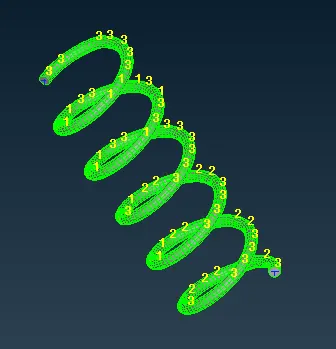
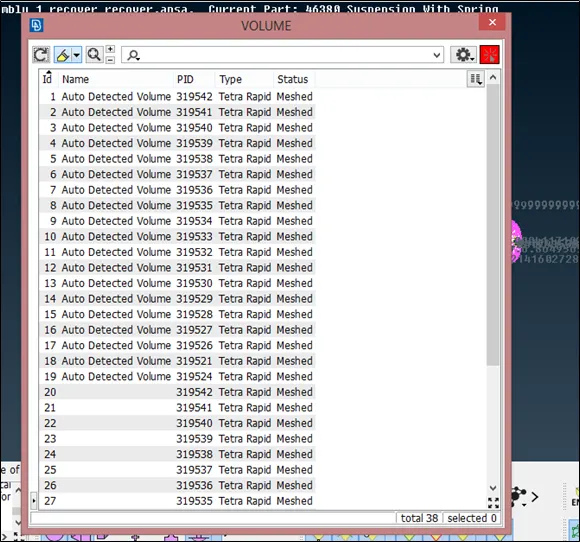
DEFINED VOLUME LIST:
CONNECTION:
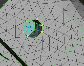
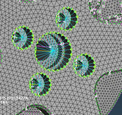
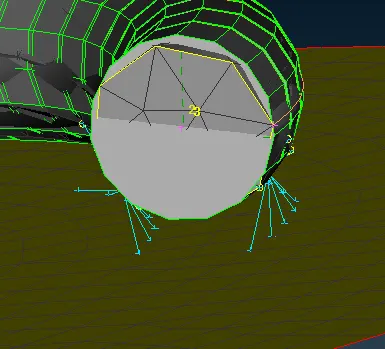
1. Use RBE2 many nodes where the holes having same PID's.
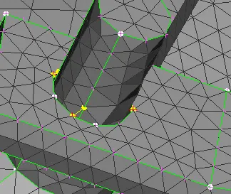
2.Use RBE2 many nodes and two nodes where faces having diferrent PID's.
3.Use two nodded RBE2 for hole and shaft type connection.
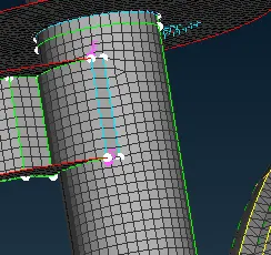
SEAM WELD:(OVERLAP SHELL)
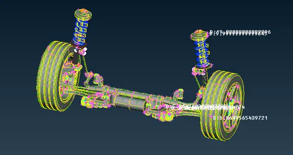
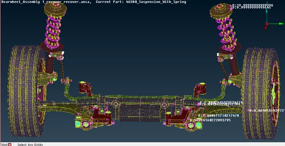
6. Use symmetric option to obtain the other side of the model
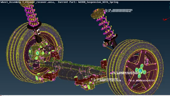
CONCLUSION:
The given suspention model has been meshed according to the given quality criteria and cleared all geometrical issues and connection are deployed at the required surface.