Meshing on the suspension Assembly
AIM:
- To check for Geometrical errors and mesh with the given element quality criteria. To Mesh the uniform components with Quad elements and Non-uniform components with Tria elements. To deploy connections wherever needed.
OBJECTIVES OF THE PROJECT:
- To identify the different components of the rear wheel assembly and distinguish whether uniform or non-uniform thickness.
- To extract mid-surface for the uniform thickness components.
- To mesh the assembly according to the given quality criteria.
- To deploy tetra mesh on non-uniform components.
- To perform de-featuring for areas required.
- To define volume for non-uniform components and deploy volume mesh for the same.
- To define the spring component as 1D CBAR element.
- To eliminate elements failing for quality criteria by fixing them.
- To eliminate tetra elements failing for collapse.
PROCEDURE:
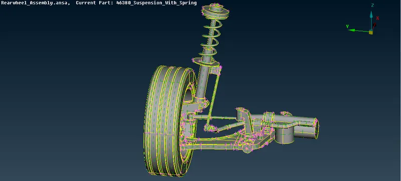
- First step is to import the Rear-wheel assembly in the ANSA software.
- The model is already stitched together, if not go to FACES > TOPO > SELECT > OK.
- This will stitch all the faces together.
- Go to TOOLS > CHECKS > GEOMETRY > EXECUTE > OK.
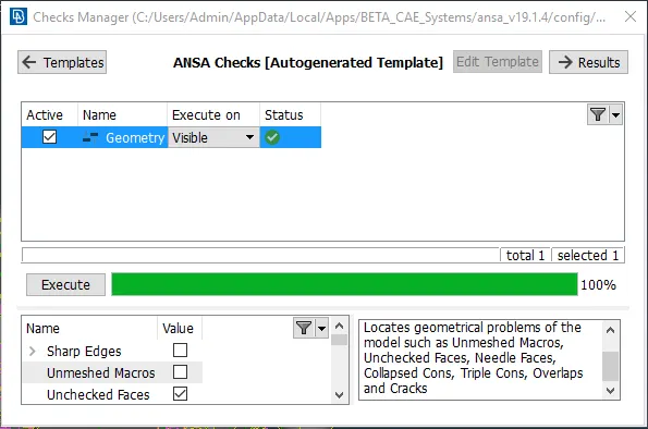
- This will check for geometrical errors. If any geometrical errors found eliminate them using auto-fix option.
- Go to UTILITIES > MESH PARAMETERS and enter the following values :
Quality Criteria for Surface Meshing of Tyre and Rim (Element type: Tria):
Target/Average Length = 6.5mm.
Go to UTILITIES > QUALITY CRITERIA and enter the following values:
Minimum Length: 5
Maximum Length: 10
Skewness: 45
Quality criteria for Surface Meshing of Non Uniform thickness components other than Tyre and Rim (Element type: Tria):
Target/Average Length = 4mm.
Go to UTILITIES > QUALITY CRITERIA and enter the following values:
Minimum Length: 2
Maximum Length: 6
Skewness: 45
Quality Criteria for Volume meshing of all Non Uniform thickness components (Element type: Tetra Elements):
Tet collapse: 0.2
Quality criteria for Mid surfacing of Uniform thickness part which has thickness less than 5 mm (Element type: Mixed elements) :
Target/Average Length = 4mm.
Minimum Length: 2
Maximum Length: 6
Maximum Aspect: 3
Warpage: 15
Skewness: 45
Jacobian: 0.7
Minimum quad angle: 45
Maximum quad angle: 135
Minimum tria angle: 30
Maximum tria angle: 120
- Use the above quality criteria when working on the respective components.
- Go to MESH MODULE > LENGTH > PRRIMETERS > 1MM > MACRO 1MM > OK so that all the length of the mesh perimeters is converted to 1mm.
- After the length is converted to 1mm the model is refined and now checks for disturbed faces.
- Go to UTILITIES > MEASURE and measure the thickness of every component.
- Identify the components with uniform thickness and components with non-uniform thickness.
- For components with uniform thickness extract mid-surface using SKIN or OFFSET option.
- Go to FACES > MID-SURFACE > SKIN > SELECT THE FACES > OK.
- This option will create the mid-surface for the component and delete the parent geometry.
- Go to FACES > OFFSET > SELECT THE FACE > ENTER THE DISTANCE > OK.
- This will offset the face by half the thickness of the component and create mid-surface without deleting the parent geometry.
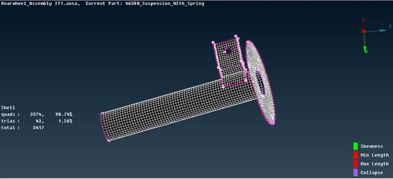
- Now for components with uniform thickness, use the above quality criteria and deploy mesh on the extracted mid-surface. Deploy MIXED element mesh.
- Go to MESH MODULE > MESH GENERATION > BEST > SELECT THE FACE > OK.
- This will deploy mixed element mesh on the mid-surface.
- Go to DRAWING STYLES > HIDDEN to check for elements failing for quality and manually improve the quality.
- Now for Tyre and Rim components, enter the given quality criteria, element type – TRIA.
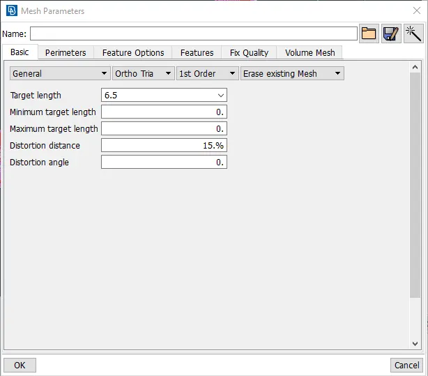
- Go to MESH MODULE > MESH GENERATION > SPOT MESH > SELECT > OK.
- NOTE- For the feature faces or curved faces deploy ORTHO TRIA and faces with straight plane deploy TRIA elements.
- ORTHO TRIA elements have the best feature capturing ability for curved areas.
- Using TRIA elements on planar areas will reduce the simulation time.
- After deploying surface mesh, check for elements failing for quality in the HIDDEN mode and manually improve them.
- This can be done by MESH MODULE > SHELL MESH > RECONSTRUCT.
- Then switch to VOLUME MESH MODULE.
- Go to VOLUMES > DEFINE > MANUAL > SELECT THE WHOLE COMPONENT AREA > OK > NEW PID > OK.
- This will define a new volume for the component.
- Go to VOLUMES > LIST > RIGHT CLICK > REMESH > TETRA RAPID > OK.
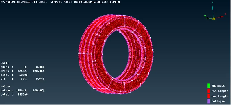
- This option forces ANSA to automatically mesh the volume using the growth ratio defined as per the algorithm.
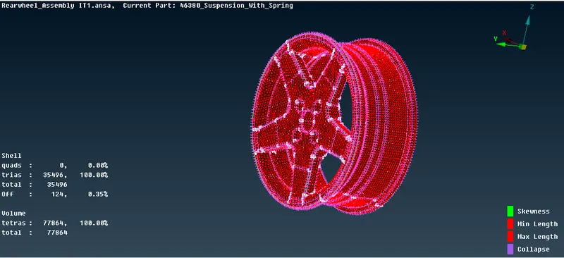
- After tyre and rim components are volume meshed change the quality criteria for the components other than tyre and rim.
- Start meshing on the non-uniform thickness components other than tyre and rim.
- Go to MESH MODULE > MESH GENERATION > SPOT MESH > SELECT > OK.
- NOTE- For the feature faces or curved faces deploy ORTHO TRIA and faces with straight plane deploy TRIA elements.
- ORTHO TRIA elements have the best feature capturing ability for curved areas.
- Using TRIA elements on planar areas will reduce the simulation time.
- After deploying surface mesh, check for elements failing for quality in the HIDDEN mode and manually improve them.
- This can be done by MESH MODULE > SHELL MESH > RECONSTRUCT.
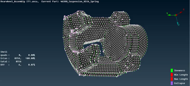
- Then switch to VOLUME MESH MODULE.
- Go to VOLUMES > DEFINE > MANUAL > SELECT THE WHOLE COMPONENT AREA > OK > NEW PID > OK.
- This will define a new volume for the component.
- Go to VOLUMES > LIST > RIGHT CLICK > REMESH > TETRA RAPID > OK.
- This option forces ANSA to automatically mesh the volume using the growth ratio defined as per the algorithm.

- Similarly, deploy mesh on all the components.
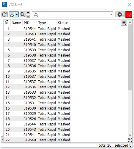
- Now, for the spring element go to TOPO MODULE > CURVES > MIDDLE and create a middle curve for the spring.
- Go to CURVES > CONNECT > MULTI and connect the curves to convert it into a single curve.
- Measure the diameter of the spring wire.
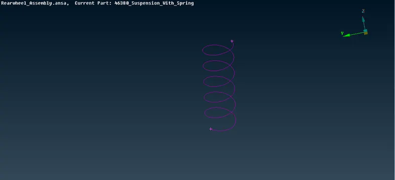
- Go to TOPO MODULE > POINTS > ON COG > SELECT THE CURVE > OK.
- This will create a COG point on the spring curve, reference for the orientation purpose.
- Go to NASTRAN DECK > ELEMENTS > CBAR > ORIENT WITH NODE > CURVE(BOX) > SELECT THE CURVE > SELECT THE COG POINT > SPECIFY ELEMENT LENGTH > NEW PID > ENTER RADIUS > OK.
- Entering the radius in the A box in the PID card will automatically calculate the area for the spring.
- This will create line elements of 4mm on the spring curve.
- Go to UTILITIES > QUALITY CRITERIA > PRESENTATION PARAMETERS > DRAW SHELL AS SOLID > LINE ELEMENTS > SOLID > OK.
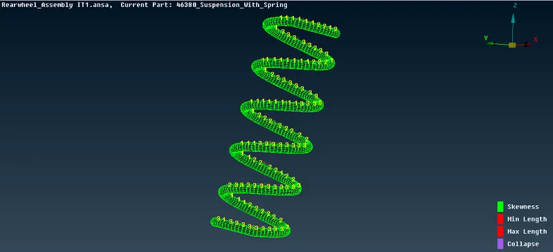
- This option will assign the thickness for the 1D element and will represent the spring cure as a solid element.
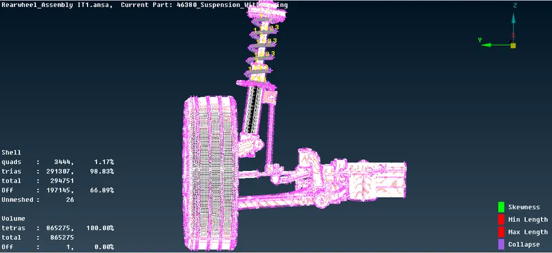
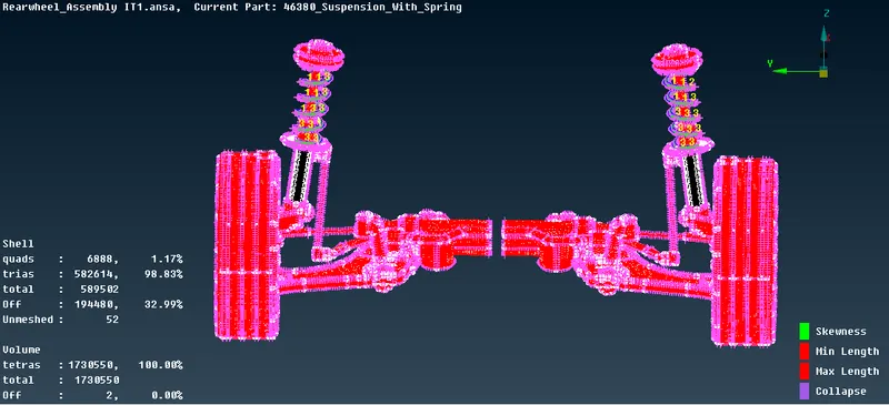
- After this, we have to perform symmetry operation for the total assembly.
- Go to UTILITIES > TRANSFORM > COPY > ENTITIES > SYMMETRY > DEFAULT SYMMETRY PLANE > APPLY > OK.
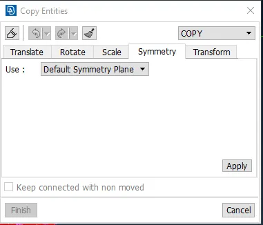
- Now the assembly is copied along with the mesh and symmetric model is obtained.
- Go to FILE > SAVE > OK.
CONCLUSION:
- By performing this project we conclude that the preprocessing for the rear wheel assembly using ANSA software is completed and the model is ready for processing.
LINK FOR THE MODEL:
https://drive.google.com/file/d/1VDaN0NDbLIcWK87fjn79KiZA5ShkTaOX/view?usp=sharing