Project-2-Meshing of Door Inner Panel Challenge
OBJECTIVE:
meshing the given side door inner plastic component according to the given quality parameters by using hypermesh.
CAD MODEL :
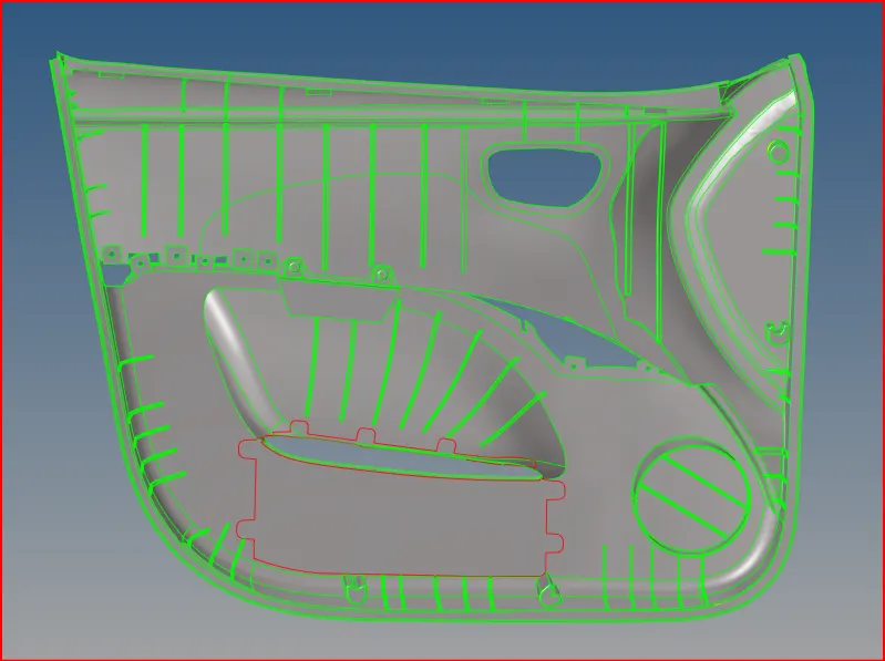
figure:1.1
PROCEDURE:
midsurface extraction:
i have extracted midsurface by using Auto midsurafce method. offset+plane+sweep option. the result of the midsurface is shown in the below figure.
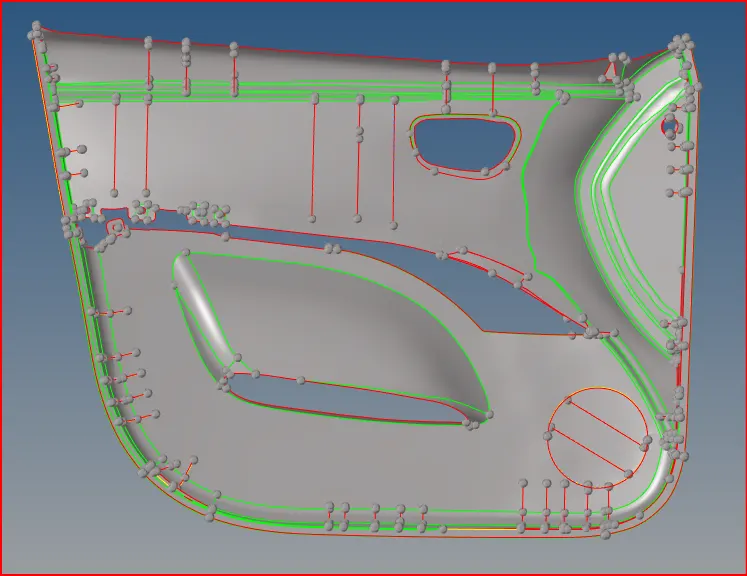
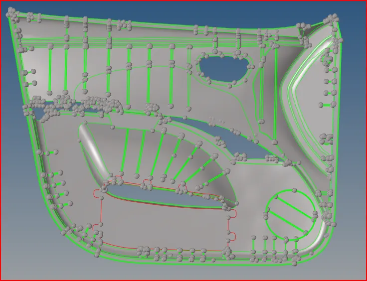
figure:2.1 shows the midsurface.(auto extraction) figure:2.2 shows the parent geometry.
- almost 80% of the surfaces were extracted automatically in midsurfacing process.there are some surfaces missing in the midsurface. so, i manually extract those surfaces to the midsurface component.
- after extraction of missing surfaces to the midsurface. the midsurface is shown below;
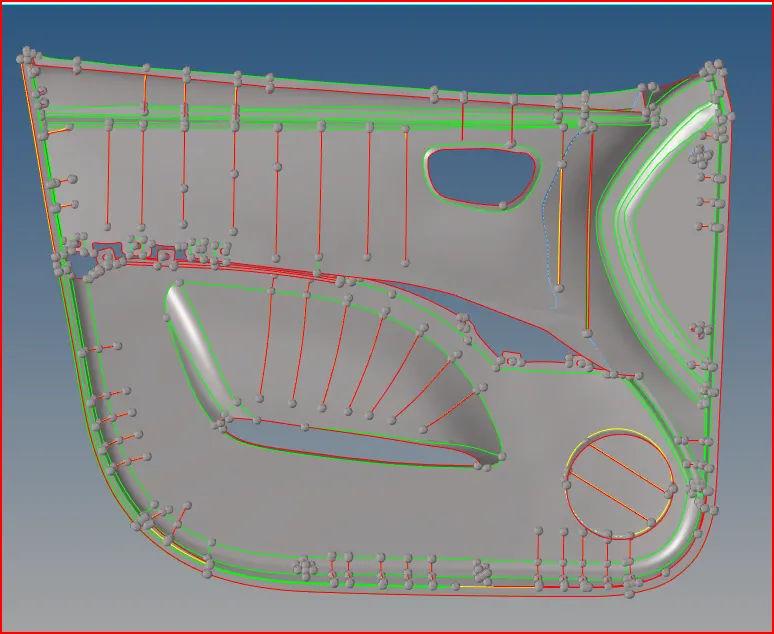
figure:3.1
geometry cleanup:
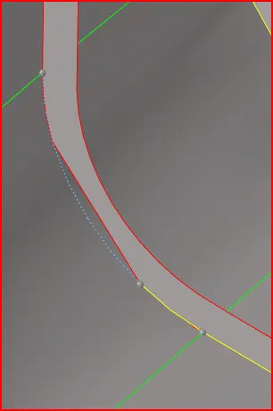
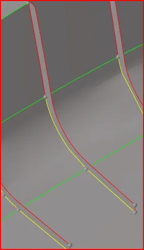
figure: 4.1 shows the before geometry celanup. figure:4.2 shows the after geometry celanup.
- the single edge is transforemed in to the triple edge. by using surface edit (shift+f9) option. i have chosen the surface with surface trim option.
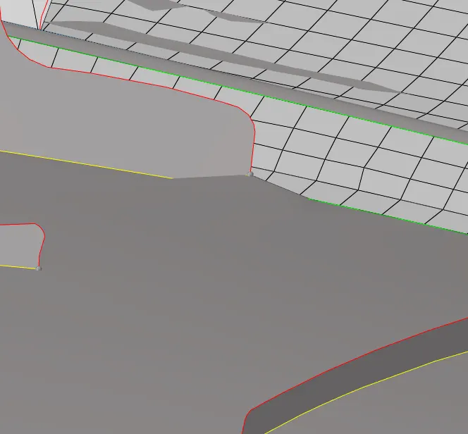
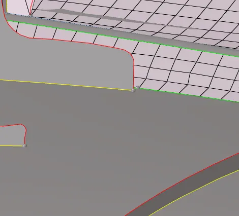
figure:5.1 before the surface cleanup. figure:5.2 after surafce cleanup.
- in the above picture(5.1) shows that surface had some issue like it was looking like abnormal. To clean up this we have choosen release point option which is in qucik edit panel(f11).
- next we got a good looking surface.
Quality prameters:
- following quality criteria is very much important in industrial point of view.
given quality parameters are shown below;
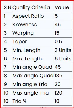
figure: 6
click on preferences --> criteria file settings. then, enter the above criteria in the criteria columns. as shown below.
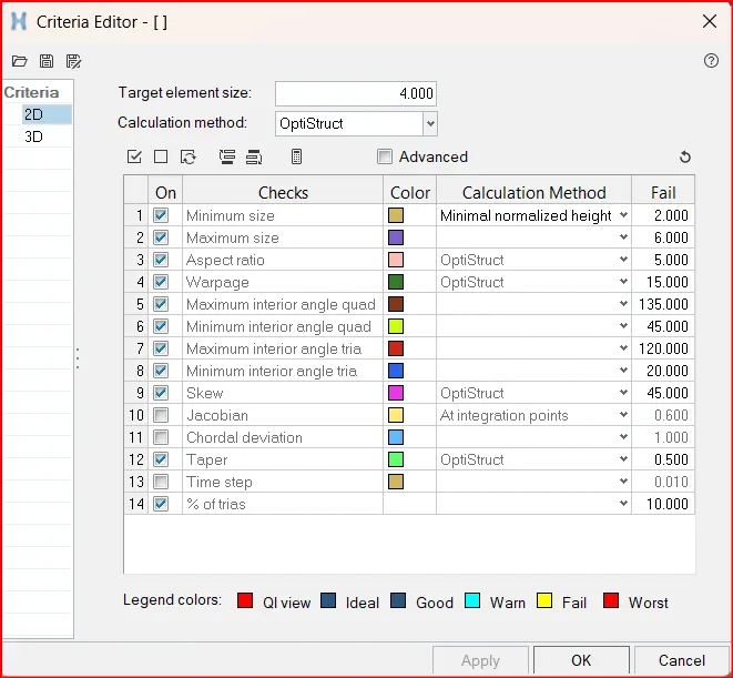
figure :7
MESHING THE MODEL:
- using automesh (f12) we can mesh the cad model. give the target element size to 4, as given in the quality criteria.
- process of meshing is simple. (f12) Automesh --> check on the flow and map in the automesh panel and check on the link opposite edges with AR<. later select the surface which has to be meshed and click mesh option and arrange the elements in a good flow and check the elements as per quality parameters.
 figure:8
- even though having good geometry cad model, if we mesh in single shot we can't get the good mesh so in order to get the good flow of the mesh, lets make some partitions in the geometry as per required.
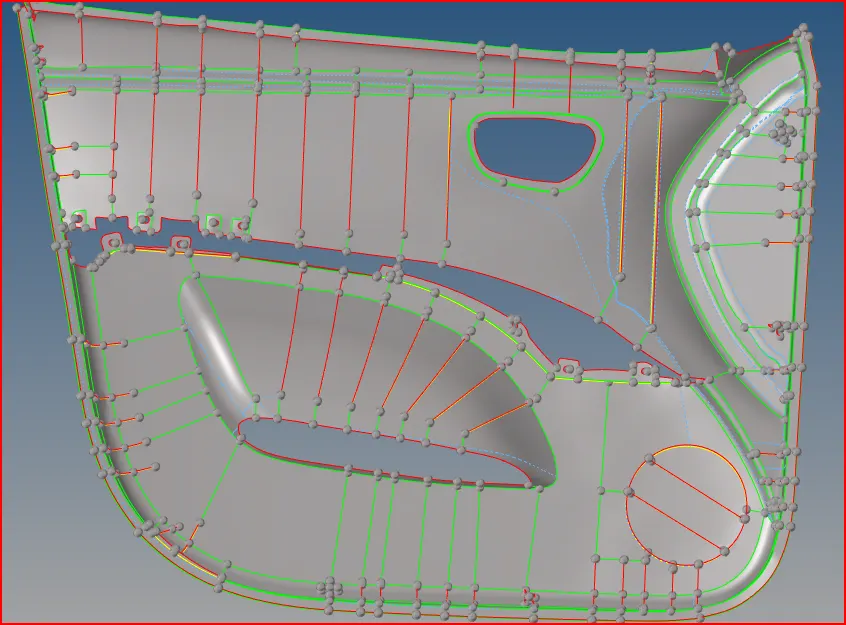
figure:9
- in the above picture, we have made some partitions on the geometry. to avoid messy flow of the mesh and multiple trias.
- maximum we would like to prefer the quad elements rather than the trais.
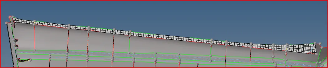
figure:10
- initially, i was started meshing up from the top. as shown in above image.
- the meshing process will be simple when we take good geometry divisions. as we have taken good geometry divisions previously, we have got good flow mesh as shown in below figure.
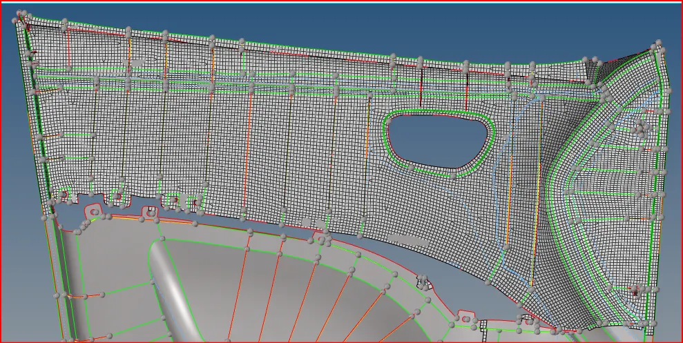
figure : 11
- the complete mesh of the model is shown in below image.
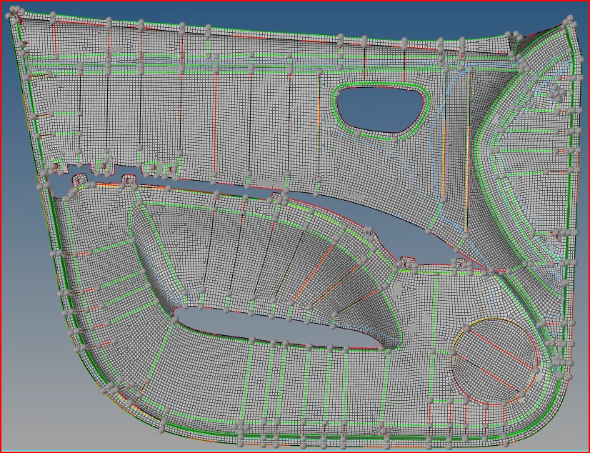
figure: 12
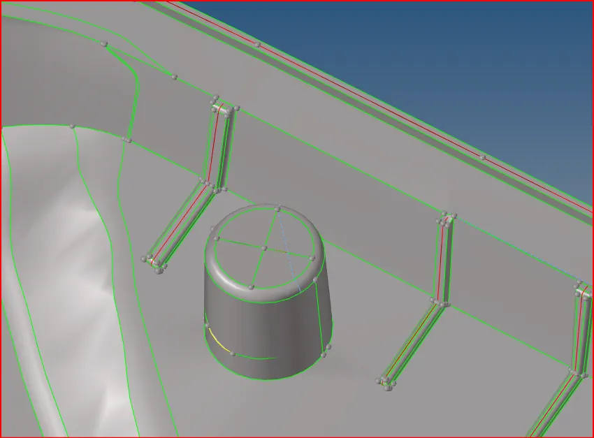
figure:13
- in the above image we have an 2d structure, which can nit be able to take midsurface. so, for this i have done a cross section lines on top of the 2d structure, and later extract those lines on the below surface.
- next, create the surface using ruled option in surface panel.

figure:14
- hence, the surface was created and ready to mesh it.
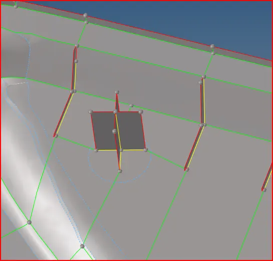
figure:15
- the meshed portion of the structure is shown below.
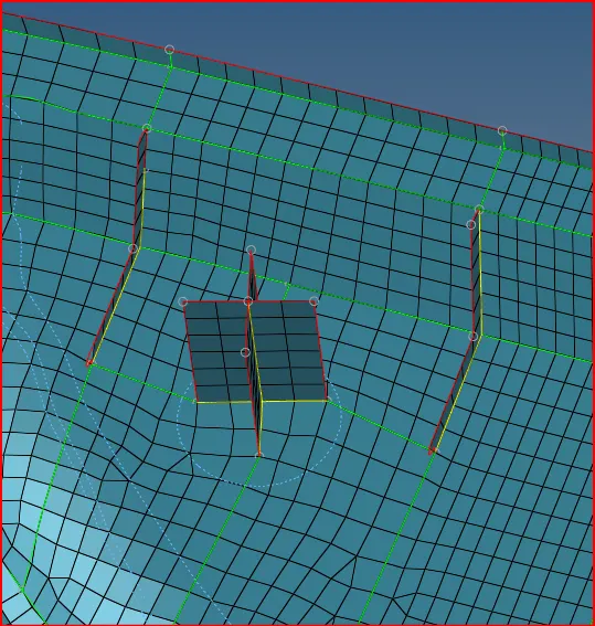
figure:16
assigning thickness:
- this is an plastic component. we can not say that plastic should have the uniform thickness.
- in this component, we have multiple thickness, ribs having different thickness, and surfaces having different thickness.
- so, we can not able to assign the auto thickness to this component.
- there is no other way rather than to assign thickness manually.
- in this process, i am going to create the diffenrent dupliicate components, based on the same thickness. and assiging the thickness to the current components as shown in below figure.
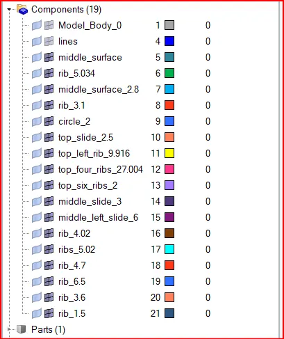
figure :17
- firstly, iam going to organize the different components in the same thickness.
- tool bar ---> organize.
- select the elements and organize to the destination componnet with its thickness. and click move on its right. then the elements will be organized.
- create properties having different thickness by measuring the component thickness. and give the particular thickness in the thickness coloumn of the property.
- now assign the thickness property to the duplicate component which we have already created.
- in the same way, slelect the thickneess of the component and create the duplicate coponent on its name ex: rib_2.5,side bar_3.5, bottom ring_4. later create the property and assign that property to the particular component. thus, thickness is applied to the components.
- to visualize the mesh with thickness, click on the 2D detailed representation icon.

figure:18
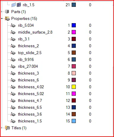
figure:19
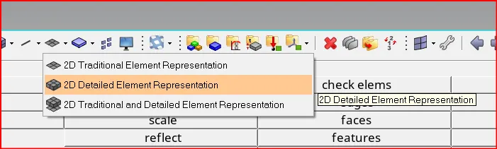
figure:20
- after assigining thickness to the elements, the model is shown in below image
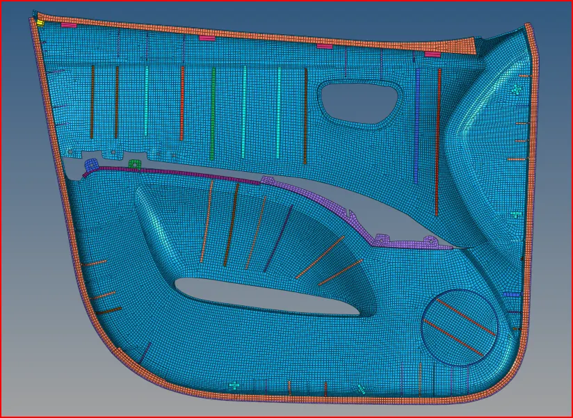
figure:21
RESULT:
this plastic component is a good challenge to learn and improve the different technics in hypermesh.
having multiple no.of thikcness and assigning thickness is the new thing which i have learn in this project.
the final model of the given component is provided in the below link.
link:
https://drive.google.com/file/d/1u2-Br3-o0iNfQxhG6KFqbt5aYr3vfDeO/view?usp=sharing