Project 2-Highway Assistant-Lane Changing Assistant
Final Project
Highway Lane Changing Assistant
Aim:
To develop specific requirement of Highway Lane Changing Assistant algorithm in MATLAB/ Simulink by following MBD guidelines and to generate the code using AUTOSAR coder. To create the SLDD file and to link with model. To map the input and output signal using AUTOSAR editor.
Principle:
Highway Assistant is a partially automated driving function on highways. It combines the radar-based Adaptive Cruise Control (ACC) with the video-based lateral guidance of lane keeping support in one system. Highway Assistant can be supplemented by an automatic lane change initiated and monitored by the driver.
The Lane Change Assistant works by using two mid-range radar sensors that are concealed in the rear bumper, one on the left and one on the right. These two sensors monitor the area alongside and behind the car. Powerful control software collates the sensor information to create a complete picture of all traffic in the area behind the vehicle. Whenever another vehicle approaches at speed from behind or is already present in the blind spot, a signal such as a warning light in the side mirror alerts the driver to the hazard. Should the driver still activate the turn signal with the intention of changing lanes, the system issues an additional acoustic and/or haptic warning.
Software used:
- MATLAB/ Simulink
Procedure:
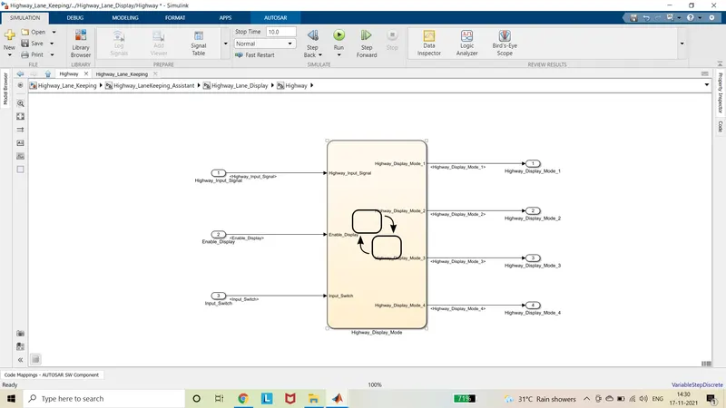
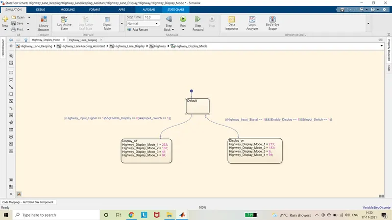
- According to the given requirement 1, the input signals to the Highway subsystem are Highway_Input_Signal, Enable_Display and Input_Switch.
- If the Highway_Input_Signal = 1, Enable_Display = 0 and Input_Switch = 1 then the outputs are Highway_Display_Mode_1 = 232, Highway_Display_Mode_2 = 183, Highway_Display_Mode_3 = 41 and Highway_Display_Mode_4 = 94.
- If the Highway_Input_Signal = 1, Enable_Display = 1 and Input_Switch = 1 then the outputs are Highway_Display_Mode_1 = 213, Highway_Display_Mode_2 = 183, Highway_Display_Mode_3 = 9 and Highway_Display_Mode_4 = 94.
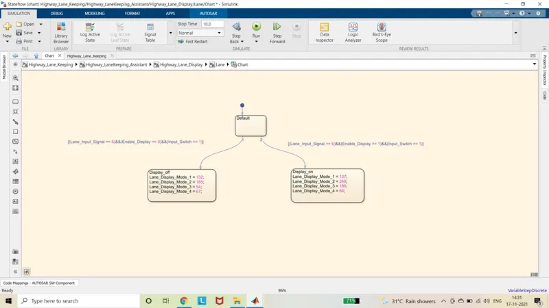
- According to the given requirement 1, the input signals to the Lane subsystem are Lane_Input_Signal, Enable_Display and Input_Switch.
- If the Lane _Input_Signal = 1, Enable_Display = 0 and Input_Switch = 1 then the outputs are Lane _Display_Mode_1 = 232, Lane _Display_Mode_2 = 183, Lane _Display_Mode_3 = 41 and Lane _Display_Mode_4 = 94.
- If the Lane _Input_Signal = 1, Enable_Display = 1 and Input_Switch = 1 then the outputs are Lane _Display_Mode_1 = 213, Lane _Display_Mode_2 = 183, Lane _Display_Mode_3 = 9 and Lane _Display_Mode_4 = 94.
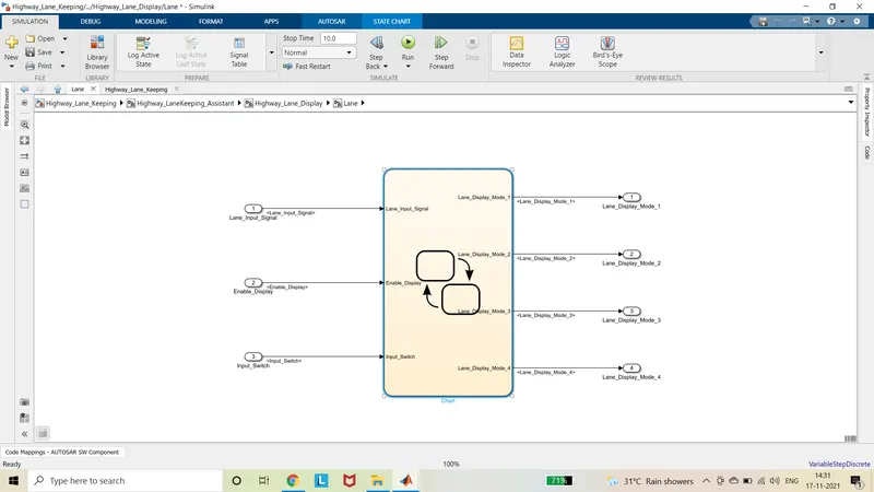
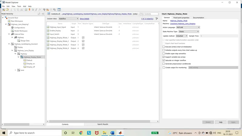
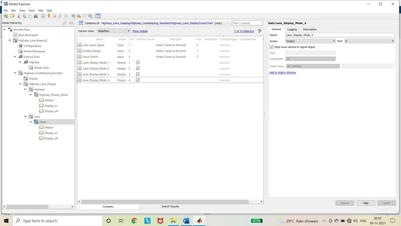
- The inputs and outputs are defined in the chart model explorer.
- The outputs of the chart must be resolved to signal.
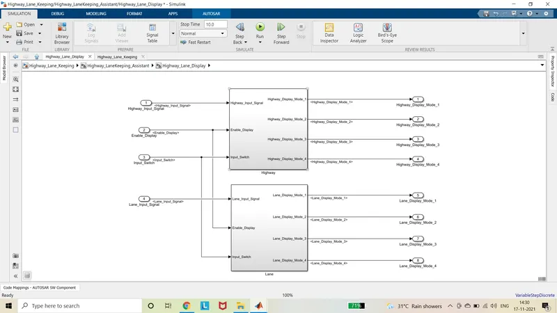
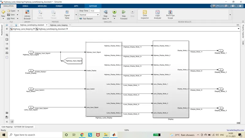
- The outputs of the above requirements are the inputs to the requirement 3.
- The first output of requirement 1 and first input of requirement 2 is connected to the first and third input of the switch 1.
- The second input of the switch 1 which is the control input is connected to the Higway_Signal_Input.
- If the Higway_Signal_Input is 0 then Highway_Display_Mode_1 is given as out as Display_Mode_1.
- If the Higway_Signal_Input is 1 then Lane_Display_Mode_1 is given as out as Display_Mode_1.
- Similarly, the three other switches are connected to the outputs of requirements 1 and 2.
- The other outputs of requirement 3 are Display_Mode_2, Display_Mode_3 and Display_Mode_4.
- The inputs of switch 2 are Highway_Display_Mode_2 and Lane_Display_2 and the control input is Highway_Signal_Input and the output is Display_Mode_2.
- The inputs of switch 3 are Highway_Display_Mode_3 and Lane_Display_3 and the control input is Highway_Signal_Input and the output is Display_Mode_3.
- The inputs of switch 4 are Highway_Display_Mode_4 and Lane_Display_4 and the control input is Highway_Signal_Input and the output is Display_Mode_4.
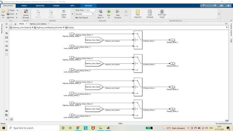
- The sldd file was created by expanding the modelling in the top pane and selecting the data dictionary.
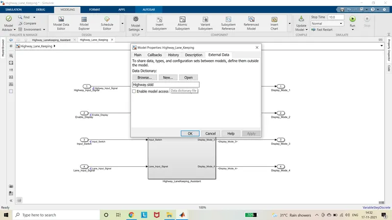
- The sldd file is linked to model by selecting Link to Data Dictionary in the Modelling in the top pane.
- All the input and output signals are defined in the Data dictionary.
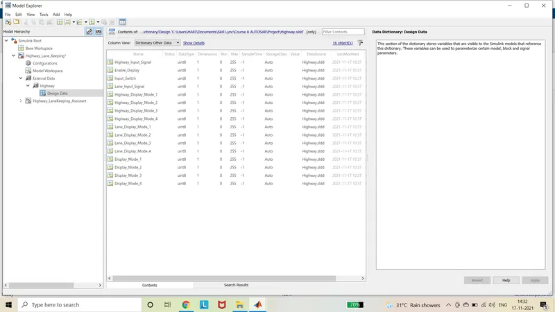
- The input signals in the model are selected and in the signal properties, the Signal name must resolve to the Simulink signal object is enabled.
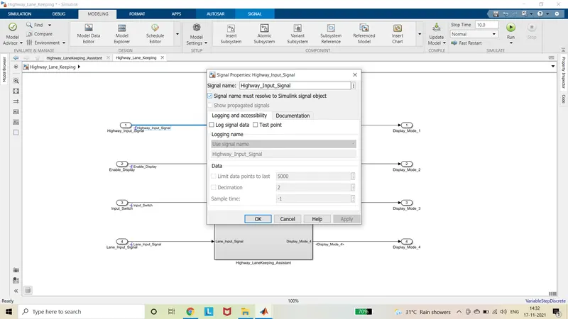
- The following signals are selected and in the signal properties, Show propagated signals is enabled.
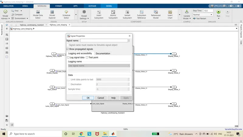
- As per the MBD rules, top most level of the system should consist of one subsystem with input and output signals.
- The signal name must be placed in the beginning of the signal.
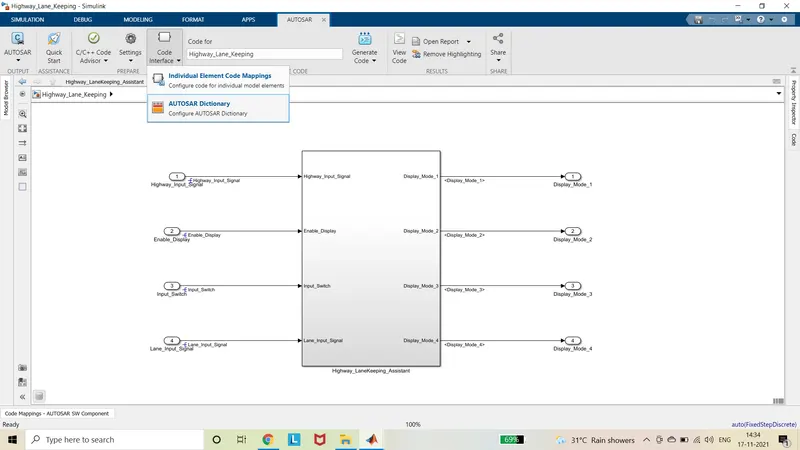
- The AUTOSAR component is selected from the APPS in the top pane. And The AUTOSAR Dictionary is selected from the Code Interface of the AUTOSAR.
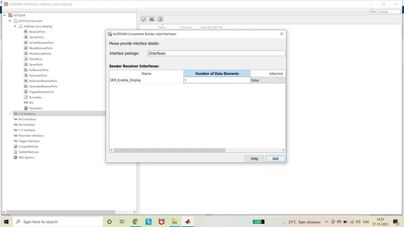
- The interface of input signals are defined by adding in the S-R interface of AUTOSAR data dictionary as SRIf_signalname and the data element is changed to 1.
- The data element is renamed as DE_signalname as per the interface.
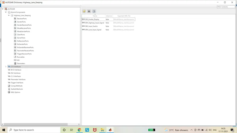
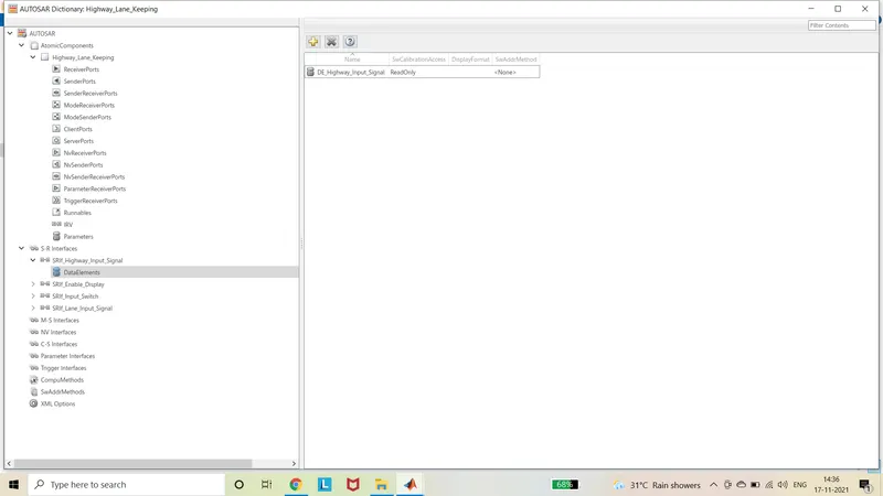
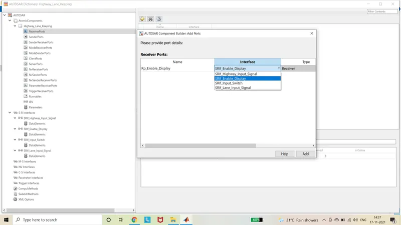
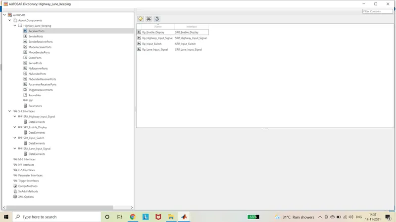
- The input signals are defined in the AUTOSAR dictionary by selecting the Receiver ports and add the signals in the format of Rp_signalname and corresponding interface is selected.
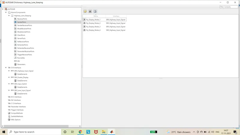
- The output signals are defined in the AUTOSAR dictionary by selecting the Receiver ports and add the signals in the format of Pp_signalname and corresponding interface is selected.
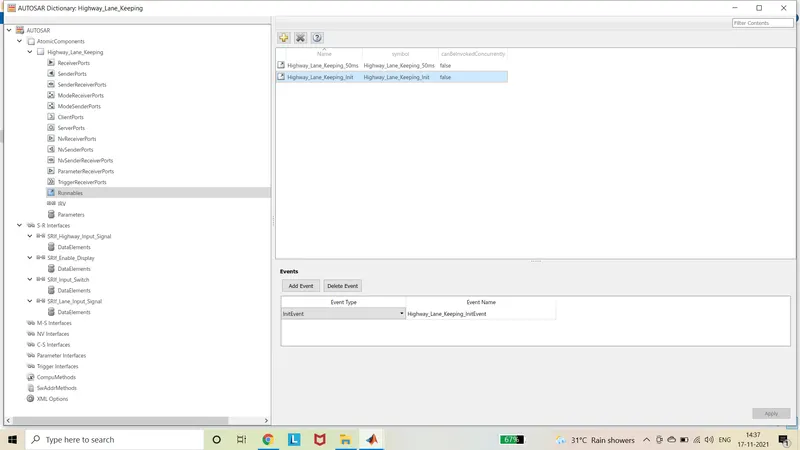
- The Runnables are added by adding the timing event and Initialization event in the format like modelname_50ms and modelname_Init.

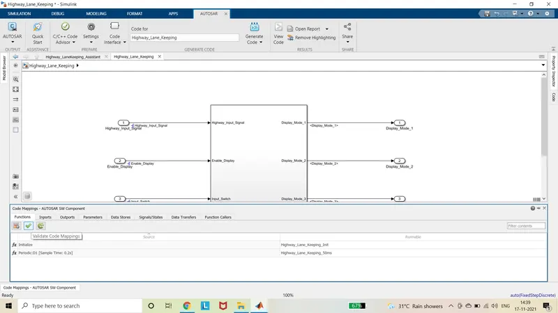
- Until the signals are mapped they are indicated as yellow colour in the bottom pane of the AUTOSAR SW component.
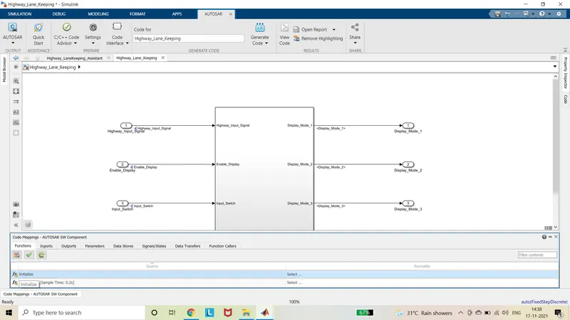
- Thus they are mapped by selecting the appropriate runnables in the functions and interface and data element in the Inports and Outports.
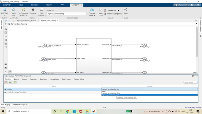
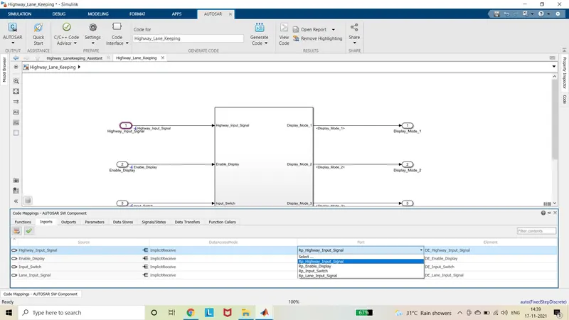

- And update the model by clicking the green curved arrow and validate the model by selecting the green tick.
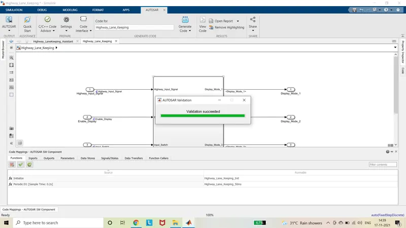
- And Model advisor report has to be generated by running the Modelling Standards of ISO 26262 and Modelling Standards of MAB test.
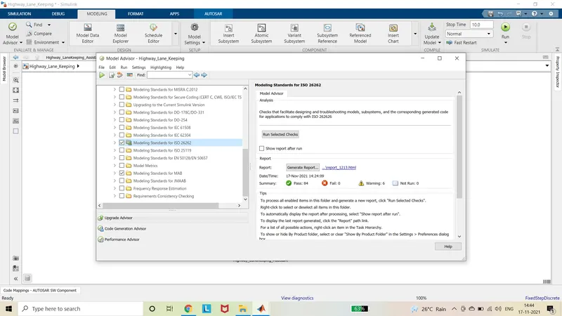
- The warning and errors must be nullified to maximum extent.
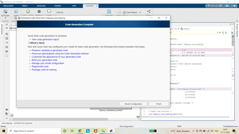
- Finally, AUTOSAR code can be generated by selecting the Quick Start in the AUTOSAR app and follow the further steps.
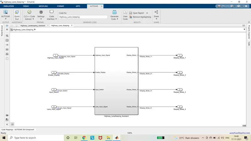
- The code generation report can be viewed by selecting the View Code generation report in the Embedded coder Quick start window.
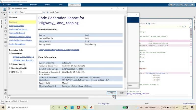
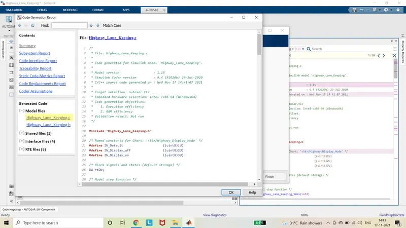
- The generated can be viewed by selecting the model files, shared files, interface files and RTE files in the left pane of the Code Generation Report.
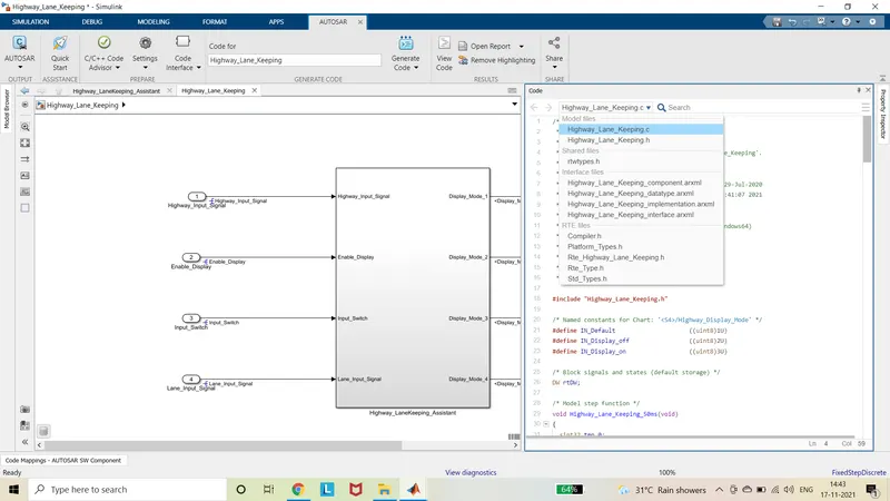
- The model is simulated to check the proper running of the model.
Summary:
The model is designed as the requirement and MBD guidelines. The signals are mapped with AUTOSAR component and code is generated by using AUTOSAR coder.
Drive Link:
https://drive.google.com/drive/folders/1eahshSBpJ78cOg1LXXvjwAGM6D5b5r6g?usp=sharing