Project 2-Highway Assistant-Lane Changing Assistant
AIM: to develop the Lane Changing Assistant feature that can assist driving and develop one specific requirement of Highway Assistant – Lane Changing Assistant algorithm.
Objectives:
- Developing the Lane Changing Assistant feature as per the Requirement Document using MATLAB Simulink.
- To Follow all the MBD related processes: Requirement Tagging & Traceability, SLDD creation, Configuration Parameter changes, Model Advisor check & Code Generation.
- This model must be developed in MATLAB Simulink per MBD guidelines.
- Code Generation Profile must be Autosar Coder.
- Simulink Data Dictionary must be created for the model & must be linked to the model.
- All the input & output signals must be mapped into the Autosar Editor.
- Model Advisor Report generation followed by Code Generation.
Theory:
Changing lanes always poses a risk, especially if a vehicle in the neighboring lane is going faster. Then there is the blind spot to consider – an area behind the car that is not visible in the external rearview mirrors. Valeo’s Lane Change Assist system alerts the driver if there are vehicles in this area or vehicles approaching rapidly from the rear. This information is extremely valuable, especially if the driver suddenly decides to change lane.
A radar sensor on each side of the rear of the car detects any vehicle (car, truck, motorbike) near and behind the vehicle.
Vehicles passing in the opposite direction, or overtaken, are detected but not signaled. The driver receives the information in the form of a signal intelligently integrated into the exterior rearview mirror. The information is indicated immediately and intuitively.The lane change assistance system uses radar sensors that scan the surrounding area using a number of different radar beams. The fully electronic radar does not have any moving parts and operates in nearly all weather conditions.
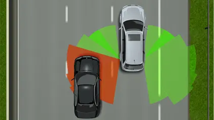
Functional description of the lane change assistant
The lane change assistant "Side Assist" takes effect from a speed of 30 km/h. The sensing area (A) of the radar sensors is approx. 50 m to the rear and approx. 3.6 m (B) to the side of the vehicle.
The system uses radar sensors to monitor the traffic behind and next to the vehicle. The area monitored includes the "blind spot" which the driver cannot see on both the driver and passenger sides.
If there is a vehicle in the monitored area and if a lane change is not taking place, the driver is informed by the LED displays in the right and left outside mirrors lighting up a little. The luminous intensity is lower so the driver is not distracted unnecessarily. In this situation, should the driver actuate the direction indicator lever for changing lane, he or she is warned by the warning lamp in the outside mirror of the corresponding side flashing intensively.
If the system senses a vehicle, the control unit in question also calculates the time remaining before a potential collision. This evaluation is used by the system to distinguish between vehicles which are approaching, flowing with the traffic and falling behind.
LANE CHANGE ASSIST: STRUCTURE AND FUNCTION
One technical innovation within driver assistance systems is the lane change assistant. This assistant informs the driver of potential hazards when changing lane on roads and highways with several lanes. It serves to prevent accidents and therefore helps to improve safety on the road.
In this section, the following pieces of system information are outlined taking the "Audi Side Assist" driver assistance system as an example.
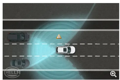

RADAR SENSORS: BASICS
More and more driver assistance systems are increasingly being fitted with radar sensors for driver assistance. One advantage of this technology is that radar sensors can achieve a precise measurement result regardless of the weather. For the main part, people associate the word "radar" with aviation or shipping. These systems have long become established and proven themselves in such applications. "Radar" is the abbreviation for Radio Detection and Ranging.
Put simply, a radar unit transmits focused electromagnetic waves, known as primary signals, at the speed of light. When these waves encounter an object, they are reflected as echoes (secondary signals) and received and evaluated by the system. Direction, distance and speed can then be determined in the system's evaluation electronics.
The sensor records speed, angle and distance information for objects within a distance of up to 70 m behind the vehicle and then evaluates the information. The LFMSK (Linear Frequency Modulation Shift Keying) process has been used since the first generation of devices.
This process can be used to sense and determine the distance and relative speed of several objects with just one signal (chirp), the frequency of which changes over time.
In the third generation of radars, an enhanced FM variant is used. Here the modulation bandwidth is limited to max. 200 MHz. The system operates at an average transmission power of 13 dBm (EIRP) in a frequency range of between 24.05 and 24.25 GHz. The resultant spatial resolution of 0.75 m is suited to the rear-end functions undertaken. The monopulse method is used here to determine the angle. On the basis of specific signal-processing approaches, the system uses various receive paths to compare the phases of the radar reflections.
Another safety function, the exit assistant, is integrated in the fourth generation radar sensors. This detects dangerous situations, such as passing cars, before exiting the vehicle and warns all passengers.
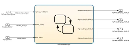
Requirement No 1 [Highway_DisplayUnit]:
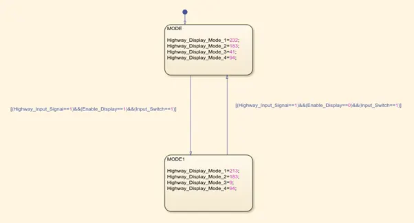
Inputs to this particular subsystem are “Highway_Input_Signal”, “Enable_Display”, “Input_Switch”. These three input signals, when assigned to a particular value will give output signals of specific value. The output signals are “Highway_Display_Mode_1”, “Highway_Display_Mode_2”, “Highway_Display_Mode_3”, “Highway_Display_Mode_4”. The requirement must be implemented in the form of a Stateflow logic.
|
Condition |
Action |
|
Highway_Input_Signal = 1 Enable_Display = off Input_Switch = on |
Highway_Display_Mode_1 = 232 Highway_Display_Mode_2 = 183 Highway_Display_Mode_3 = 41 Highway_Display_Mode_4 = 94 |
|
Highway_Input_Signal = 1 Enable_Display = on Input_Switch = on |
Highway_Display_Mode_1 = 213 Highway_Display_Mode_2 = 183 Highway_Display_Mode_3 = 9 Highway_Display_Mode_4 = 94 |
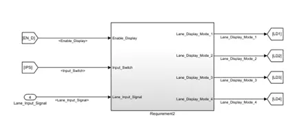
Requirement No 2 [Lane_DisplayUnit]:
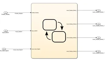
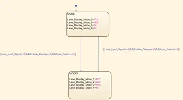
Inputs to this particular subsystem are “Enable_Display”, “Input_Switch”, “Lane_Input_Signal”. These three input signals, when assigned to a particular value will give output signals of specific value. The output signals are “Lane_Display_Mode_1”, “Lane_Display_Mode_2”, “Lane_Display_Mode_3”, “Lane_Display_Mode_4”. The requirement must be implemented in the form of Stateflow logic.
|
Condition |
Action |
|
Lane_Input_Signal= 6 Enable_Display = off Input_Switch = on |
Lane_Display_Mode_1 = 132 Lane_Display_Mode_2 = 185 Lane_Display_Mode_3 = 54 Lane_Display_Mode_4 = 67 |
|
Lane_Input_Signal= 6 Enable_Display = on Input_Switch = on |
Lane_Display_Mode_1 = 127 Lane_Display_Mode_2 = 248 Lane_Display_Mode_3 = 186 Lane_Display_Mode_4 = 84 |
Requirement No 3:
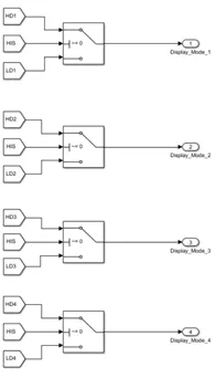
Signals coming from both subsystems “Highway_Display_Mode_1” & “Lane_Display_Mode_1” are given as inputs to a switch block which will have input signal “Highway_Input_Signal” given as 2nd input to the switch block. Corresponding output from this particular switch block is output signal “Display_Mode_1”.
Signals coming from both subsystems “Highway_Display_Mode_2” & “Lane_Display_Mode_2” are given as inputs to a switch block which will have input signal “Highway_Input_Signal” given as 2nd input to the switch block. Corresponding output from this particular switch block is output signal “Display_Mode_2”.
Signals coming from both subsystems “Highway_Display_Mode_3” & “Lane_Display_Mode_3” are given as inputs to a switch block which will have input signal “Highway_Input_Signal” given as 2nd input to the switch block. Corresponding output from this particular switch block is output signal “Display_Mode_3”.
Signals coming from both subsystems “Highway_Display_Mode_4” & “Lane_Display_Mode_4” are given as inputs to a switch block which will have input signal “Highway_Input_Signal” given as 2nd input to the switch block. Corresponding output from this particular switch block is output signal “Display_Mode_4”.
Procedure:
- The simulink model along with requirements is designed in the matlab simulink using the suitable blocks
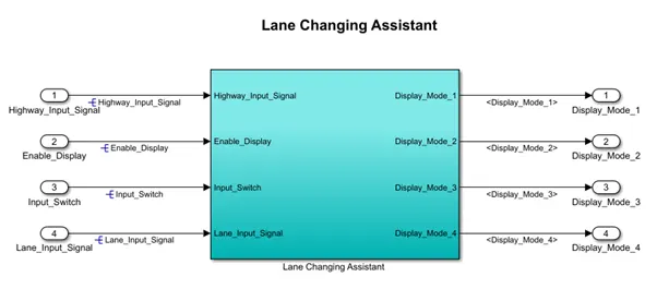
>>complete lane assist system logic
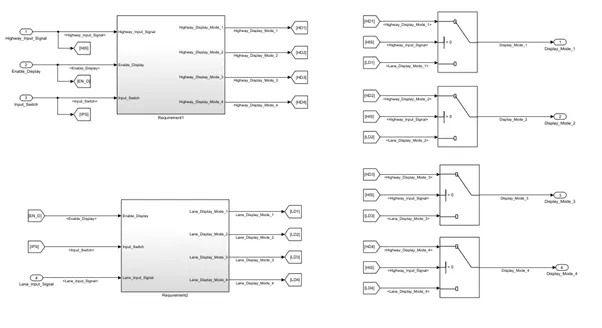
Requirement 1
Requirement 2
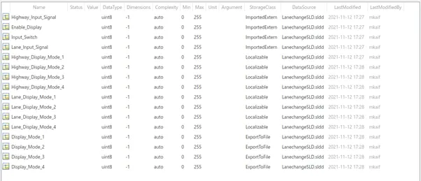
- The input,output and calibrated signals are defined in the Simulink libraby data directory file,all parameters are defined in the SLD file.
- The output of the Highway_Display_Mode and Lane_Display_Mode are provided to the Switch block. That is in total 4 switch blocks are used. The conditional input signal is taken as Highway_Input_Signal for all the blocks.
.
Requirement No 3:
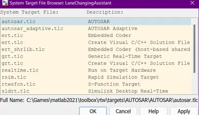
- Now we will make the model in compliance with the AUTOSAR. So, all the input & output signals will be mapped into the Autosar Editor.But prior to that, we will set the System target file as autosar.tlcWe will make sure that in Solver we will set the solver to Fixed-Step.
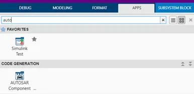
Under the app tab open the AUTOSAR component
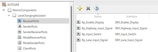
Open the code mapping for the AUTOSAR component in autosar editor

For the Reciever port of the model, that is output, we will rename the port with the prefix Rp__.
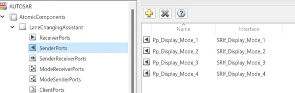
For the Sender port of the model, that is output, we will rename the port with the prefix Pp_.
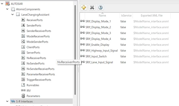
For the S-R Interfaces of the model, we will rename the port with the prefix SRIf_.
For the Data Elements of the model, we will rename the port with the prefix DE_.
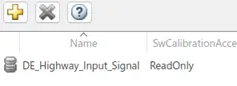
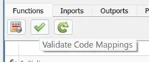
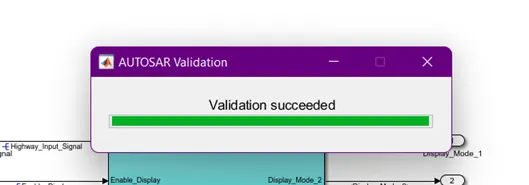
Now we validate the model according to the autosar compliance
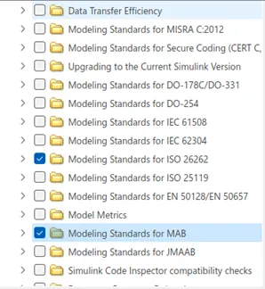
- Now we run model advisor checks on the model to see whether our model is MAB standard compliant and generate a report.

- Now we generate the C code using the autosar C code generator app
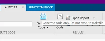
AUTOSAR C Code
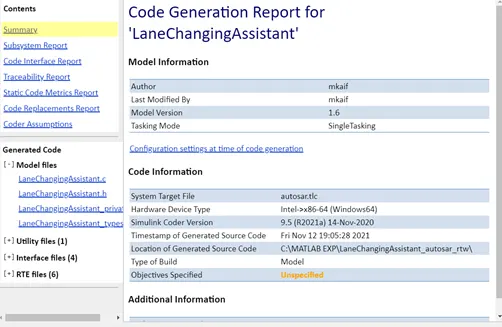
/*

 * File: LaneChangingAssistant.c

 *

 * Code generated for Simulink model 'LaneChangingAssistant'.

 *

 * Model version                  : 1.6

 * Simulink Coder version         : 9.5 (R2021a) 14-Nov-2020

 * C/C++ source code generated on : Fri Nov 12 19:05:28 2021

 *

 * Target selection: autosar.tlc

 * Embedded hardware selection: Intel->x86-64 (Windows64)

 * Code generation objectives: Unspecified

 * Validation result: Not run

 */


#include "LaneChangingAssistant.h"

#include "LaneChangingAssistant_private.h"


/* Named constants for Chart: '<S2>/Requirement 1 logic' */

#define LaneChangingAssistant_IN_MODE  ((uint8)1U)

#define LaneChangingAssistant_IN_MODE1 ((uint8)2U)


/* Block states (default storage) */

DW_LaneChangingAssistant_T LaneChangingAssistant_DW;


/* Model step function */

void LaneChangingAssistant_Step(void)

{

  sint32 rtb_Highway_Display_Mode_1;

  sint32 rtb_Highway_Display_Mode_3;

  sint32 rtb_Lane_Display_Mode_1;

  sint32 rtb_Lane_Display_Mode_2;

  sint32 rtb_Lane_Display_Mode_3;

  sint32 rtb_Lane_Display_Mode_4;

  sint32 tmp;


  /* Chart: '<S2>/Requirement 1 logic' incorporates:

   *  Inport: '<Root>/Enable_Display'

   *  Inport: '<Root>/Highway_Input_Signal  '

   *  Inport: '<Root>/Input_Switch  '

   */

  if (LaneChangingAssistant_DW.is_active_c3_LaneChangingAssist == 0U) {

    LaneChangingAssistant_DW.is_active_c3_LaneChangingAssist = 1U;

    LaneChangingAssistant_DW.is_c3_LaneChangingAssistant =

      LaneChangingAssistant_IN_MODE;

    rtb_Highway_Display_Mode_1 = 232;

    rtb_Highway_Display_Mode_3 = 41;

  } else if (LaneChangingAssistant_DW.is_c3_LaneChangingAssistant ==

             LaneChangingAssistant_IN_MODE) {

    if ((Rte_IRead_LaneChangingAssistant_Step_Rp_Highway_Input_Signal_DE_Highway_Input_Signal

         () == 1) &&

        (Rte_IRead_LaneChangingAssistant_Step_Rp_Enable_Display_DE_Enable_Display

         () == 1) &&

        (Rte_IRead_LaneChangingAssistant_Step_Rp_Input_Switch_DE_Input_Switch() ==

         1)) {

      LaneChangingAssistant_DW.is_c3_LaneChangingAssistant =

        LaneChangingAssistant_IN_MODE1;

      rtb_Highway_Display_Mode_1 = 213;

      rtb_Highway_Display_Mode_3 = 9;

    } else {

      rtb_Highway_Display_Mode_1 = 232;

      rtb_Highway_Display_Mode_3 = 41;

    }


    /* case IN_MODE1: */

  } else if

      ((Rte_IRead_LaneChangingAssistant_Step_Rp_Highway_Input_Signal_DE_Highway_Input_Signal

        () == 1) &&

       (Rte_IRead_LaneChangingAssistant_Step_Rp_Enable_Display_DE_Enable_Display

        () == 0) &&

       (Rte_IRead_LaneChangingAssistant_Step_Rp_Input_Switch_DE_Input_Switch() ==

        1)) {

    LaneChangingAssistant_DW.is_c3_LaneChangingAssistant =

      LaneChangingAssistant_IN_MODE;

    rtb_Highway_Display_Mode_1 = 232;

    rtb_Highway_Display_Mode_3 = 41;

  } else {

    rtb_Highway_Display_Mode_1 = 213;

    rtb_Highway_Display_Mode_3 = 9;

  }


  /* End of Chart: '<S2>/Requirement 1 logic' */


  /* Chart: '<S3>/Chart' incorporates:

   *  Inport: '<Root>/Enable_Display'

   *  Inport: '<Root>/Input_Switch  '

   *  Inport: '<Root>/Lane_Input_Signal'

   */

  if (LaneChangingAssistant_DW.is_active_c1_LaneChangingAssist == 0U) {

    LaneChangingAssistant_DW.is_active_c1_LaneChangingAssist = 1U;

    LaneChangingAssistant_DW.is_c1_LaneChangingAssistant =

      LaneChangingAssistant_IN_MODE;

    rtb_Lane_Display_Mode_1 = 132;

    rtb_Lane_Display_Mode_2 = 185;

    rtb_Lane_Display_Mode_3 = 54;

    rtb_Lane_Display_Mode_4 = 67;

  } else if (LaneChangingAssistant_DW.is_c1_LaneChangingAssistant ==

             LaneChangingAssistant_IN_MODE) {

    if ((Rte_IRead_LaneChangingAssistant_Step_Rp_Lane_Input_Signal_DE_Lane_Input_Signal

         () == 6) &&

        (Rte_IRead_LaneChangingAssistant_Step_Rp_Enable_Display_DE_Enable_Display

         () == 0) &&

        (Rte_IRead_LaneChangingAssistant_Step_Rp_Input_Switch_DE_Input_Switch() ==

         1)) {

      LaneChangingAssistant_DW.is_c1_LaneChangingAssistant =

        LaneChangingAssistant_IN_MODE1;

      rtb_Lane_Display_Mode_1 = 127;

      rtb_Lane_Display_Mode_2 = 248;

      rtb_Lane_Display_Mode_3 = 186;

      rtb_Lane_Display_Mode_4 = 84;

    } else {

      rtb_Lane_Display_Mode_1 = 132;

      rtb_Lane_Display_Mode_2 = 185;

      rtb_Lane_Display_Mode_3 = 54;

      rtb_Lane_Display_Mode_4 = 67;

    }


    /* case IN_MODE1: */

  } else if

      ((Rte_IRead_LaneChangingAssistant_Step_Rp_Lane_Input_Signal_DE_Lane_Input_Signal

        () == 6) &&

       (Rte_IRead_LaneChangingAssistant_Step_Rp_Enable_Display_DE_Enable_Display

        () == 0) &&

       (Rte_IRead_LaneChangingAssistant_Step_Rp_Input_Switch_DE_Input_Switch() ==

        1)) {

    LaneChangingAssistant_DW.is_c1_LaneChangingAssistant =

      LaneChangingAssistant_IN_MODE;

    rtb_Lane_Display_Mode_1 = 132;

    rtb_Lane_Display_Mode_2 = 185;

    rtb_Lane_Display_Mode_3 = 54;

    rtb_Lane_Display_Mode_4 = 67;

  } else {

    rtb_Lane_Display_Mode_1 = 127;

    rtb_Lane_Display_Mode_2 = 248;

    rtb_Lane_Display_Mode_3 = 186;

    rtb_Lane_Display_Mode_4 = 84;

  }


  /* End of Chart: '<S3>/Chart' */


  /* Switch: '<S1>/Switch' incorporates:

   *  Inport: '<Root>/Highway_Input_Signal  '

   *  Switch: '<S1>/Switch1'

   *  Switch: '<S1>/Switch2'

   */

  tmp =

    Rte_IRead_LaneChangingAssistant_Step_Rp_Highway_Input_Signal_DE_Highway_Input_Signal

    ();

  if (tmp > 0) {

    /* Outport: '<Root>/Display_Mode_1' */

    Rte_IWrite_LaneChangingAssistant_Step_Pp_Display_Mode_1_DE_Display_Mode_1

      (rtb_Highway_Display_Mode_1);

    rtb_Lane_Display_Mode_2 = 183;

  } else {

    /* Outport: '<Root>/Display_Mode_1' */

    Rte_IWrite_LaneChangingAssistant_Step_Pp_Display_Mode_1_DE_Display_Mode_1

      (rtb_Lane_Display_Mode_1);

  }


  /* End of Switch: '<S1>/Switch' */


  /* Outport: '<Root>/Display_Mode_2' */

  Rte_IWrite_LaneChangingAssistant_Step_Pp_Display_Mode_2_DE_Display_Mode_2

    (rtb_Lane_Display_Mode_2);


  /* Switch: '<S1>/Switch2' incorporates:

   *  Switch: '<S1>/Switch3'

   */

  if (tmp > 0) {

    /* Outport: '<Root>/Display_Mode_3' */

    Rte_IWrite_LaneChangingAssistant_Step_Pp_Display_Mode_3_DE_Display_Mode_3

      (rtb_Highway_Display_Mode_3);

    rtb_Lane_Display_Mode_4 = 94;

  } else {

    /* Outport: '<Root>/Display_Mode_3' */

    Rte_IWrite_LaneChangingAssistant_Step_Pp_Display_Mode_3_DE_Display_Mode_3

      (rtb_Lane_Display_Mode_3);

  }


  /* Outport: '<Root>/Display_Mode_4' */

  Rte_IWrite_LaneChangingAssistant_Step_Pp_Display_Mode_4_DE_Display_Mode_4

    (rtb_Lane_Display_Mode_4);

}


/* Model initialize function */

void LaneChangingAssistant_Init(void)

{

  /* (no initialization code required) */

}


/*

 * File trailer for generated code.

 *

 * [EOF]

 */
Result:
The Simulink model for the lane changing Assist of a vehicle was designed according to the requirements complying with the standards and converted to Autosar compliant model ,the Autosar code for the feature was generated respectively.
Conclusion:
The lane changing is an advanced feature of ADAS and has a very important role in safety for both the driver’s vehicle and the approaching vehicle ahead.
A safe and error free code for such feature is mandatory especially in autonomous cars, hence using the Autosar c coder app complying to autosar standard it was attainable effortlessly.
References
https://www.valeo.com/en/lane-change-assistance-system/