Project 2-Highway Assistant-Lane Changing Assistant
Aim: To develop the Simulation model project for Lane Changing Assistant feature of the Advance driver Assistance cruise control.
Objective:
1) Create High Display unit model of requirement 1
2) Create Lane Display unit model of requirement 2
3) Create Display mode units model of requirement 3
4) Develop model as per MBD guideline
5) Use AUTOSAR Coder for code generation.
6) Create SLDD and link with Simulink model.
7) Generate Model advisory report.
Project Description:
The Lane changing assistant is one of the Advance driver assistant feature of the Electric vehicle. It provide the safety to driver during the lane changing on highway. When driver want to change the lane, it is difficult to judge by looking in mirrors upcoming back vehicles and blind spots. To avoid the danger accident situation, this feature is developed. The lane changing feature activated when driver start to change the lane. It support to specific speed range during lane changing. To monitor the surround and back cars, the sensor are situated on the rear bumper and left-right side of the car. When the lane changing by driver and if any surround car detected by the sensors, then it indicate by light to driver.
Requirement 1:
Steps to solve requirement 1:
Step 1: create three input signals named as “Highway_Input_Signal”, “Enable_Display”, “Input_Switch”.
Step 2: create four output signals named as “Highway_Display_Mode_1”, “Highway_Display_Mode_2”, “Highway_Display_Mode_3”, “Highway_Display_Mode_4”.
Step 3: create state chart and develop state chart model as per given requirement logic.
Description of requirement 1:
This requirement 1 is to develop the model for the High way Display Mode which is the input of the requirement 3 at last. To develop the subsystem model we have taken 3 input named as “Highway_Input_Signal”, “Enable_Display”, “Input_Switch”. In the subsystem we have create the chart with two stages. In both stages of the statefolw chart we have given the conditions as Highway Input signals, Enable display, Input switch with specific values and actins Highway Display mode 1, Highway Display mode 2, Highway Display mode 3, Highway Display mode 4 .apply the language “C” for the stateflow model.
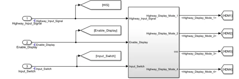
Figure 1: Requirement 1 Highway Display mode
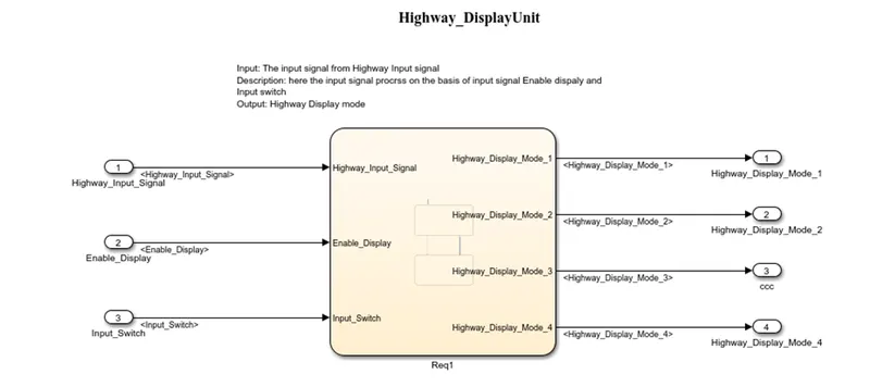
Figure: State chart of Highway Display mode
Requirement 2:
Steps to solve requirement 2:
Step 1: make subsystem, create chart inside it and connect three Input signals as “Enable_Display”, “Input_Switch”, “Lane_Input_Signal”.
Step 2: inside the chart, create two states and apply the conditions and action as per requirement.
Step 3: create four output signals name as “Lane_Display_Mode_1”, “Lane_Display_Mode_2”, “Lane_Display_Mode_3”, “Lane_Display_Mode_4”.
Description of requirement 2:
In the requirement 2, we have developed the Lane Display unit model. For this subsystem we have created three input signals. Lane input signal is one signal and other two Enable Display & Input switch are the same inputs of requirement 1. Inside the subsystem, we have created chart with 2 states. In the both states Lane Display mode 1, Lane Display mode 2, Lane Display mode 3, Lane Display mode 4 action are setup. Also, give the condition are given as per the give requirement. This model gives the output signals as Lane display mode to requirement three switch blocks.
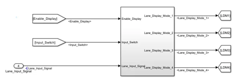
Figure: Requirement 2 Lane Display mode
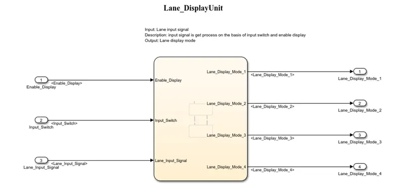
Figure: State chart of Lane Display mode
Requirement 3:
Steps to solve requirement 3:
Step 1: create the four switch block with initial condition not equal to zero.
Step 2: for each switch block apply the first input as Highway Display mode 1, Highway Display mode 2, Highway Display mode 3, Highway Display mode 4.
Step 3: for each switch block apply the third input as Lane Display mode 1, Lane Display mode 2, Lane Display mode 3, Lane Display mode 4.
Step 4: for each block apply the second input as Highway Input signal from the first requirement.
Step 4: create the four output from each switch block as Display mode 1, Display mode 2, Display mode 3, Display mode 4.
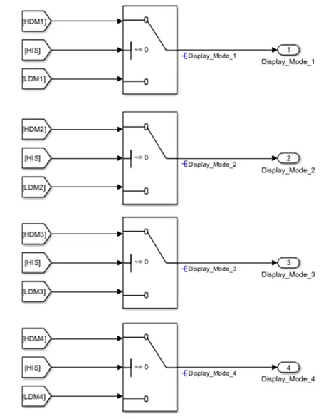
Figure: requirement 3 Display mode output
Simulink Data Library:
We have created the SLDD as per given requirement Input, Output and Local signals. We set the range for all signals as 0 to 255 with storage class as auto.
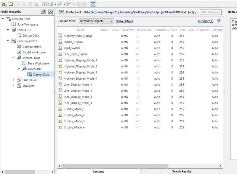
Figure: SLDD for Lane changing Assistant
Project Model:
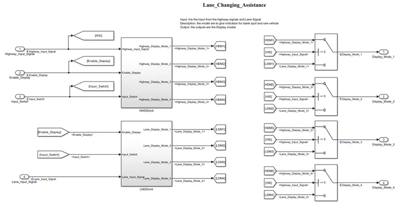
Solver setting:
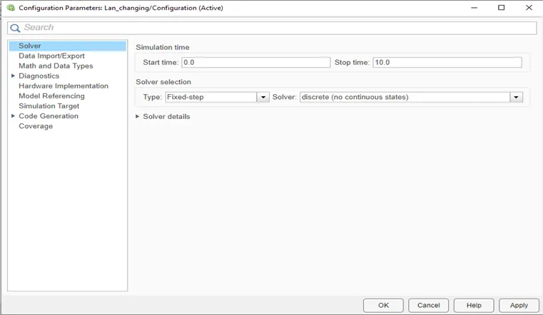
In this solver setting we select the starting time, ending time, and Fixed type solver.
Code Generation:
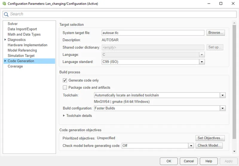
In this project we have to generate the AUTOSAR Code, so we have selected the autosar.tlc.
Model Advisory Check:
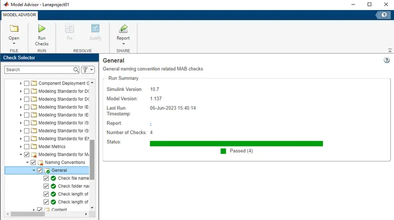
We have test the developed model as per the MAAB guideline and fix the errors and warnings. The detail report is attached with the project file.
AUTOSAR Code generation:
Steps for AUTOSAR code generation:
Step 1: set fixed type solver form model configuration and code generation language as ‘C’, autosar.tlc .
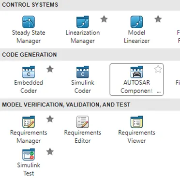
Step 2: Go to App and select Autosar component tool box and select classical, further go next and at last click on finish.
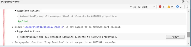
Step 3: at the bottom of window we click on small icon for code mapping ans map the signals with AUTOSAR code.
Step 4: open the Autosar directory and give all package details for xml as Implementation data type- allowed, software calibration- read only and computational method-physical to internal.
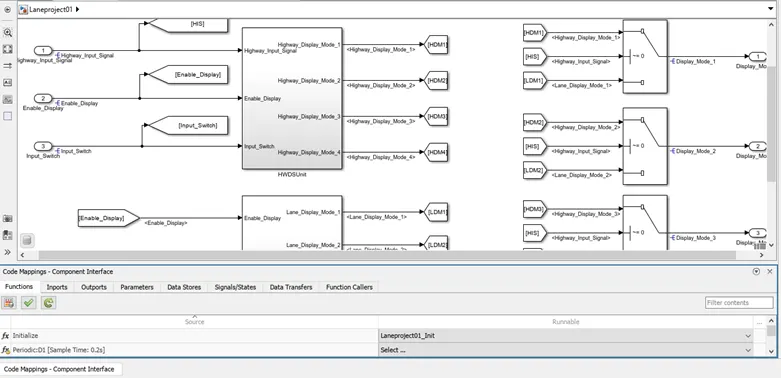
Figure. Autosar coder
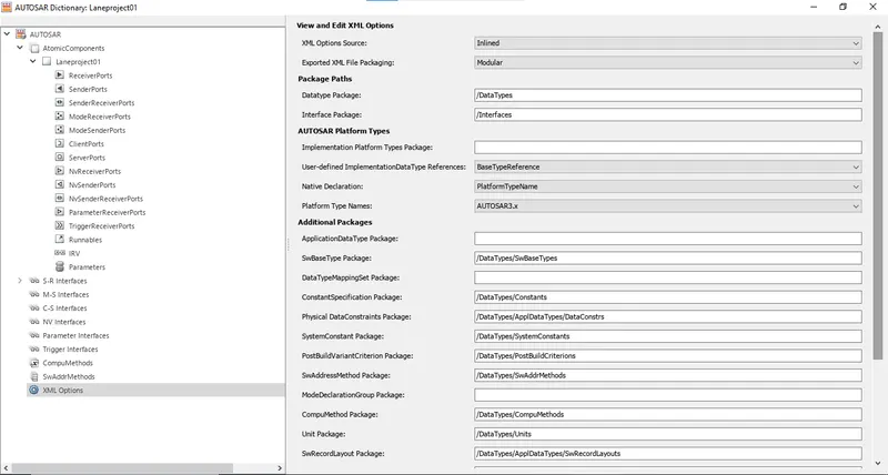
Figure. Autosar Directory
Step 5: also from the Autosar directory SR-Interface, data elements, receiver codes, sender code mapped. After complete this click on refresh and click on validation.
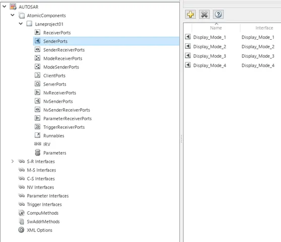
Figure. sender port
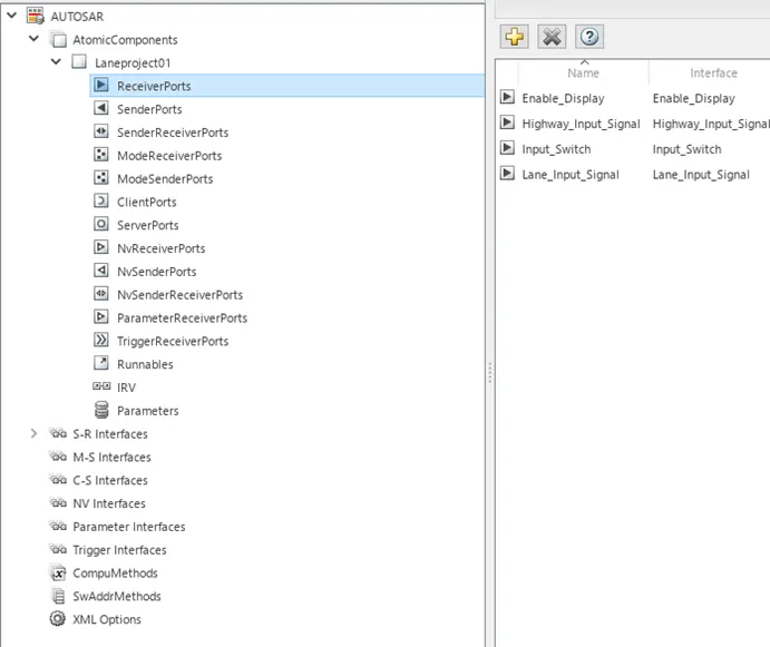
Figure. receiver port
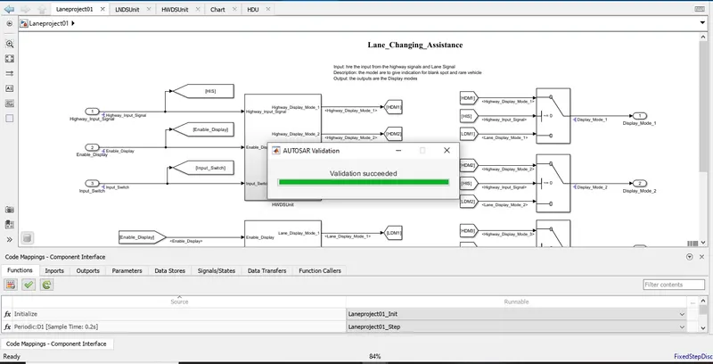
Figure. AUTOSAR Validation
Step 6: now, from the model window click on code generation for the AUTOSAR.
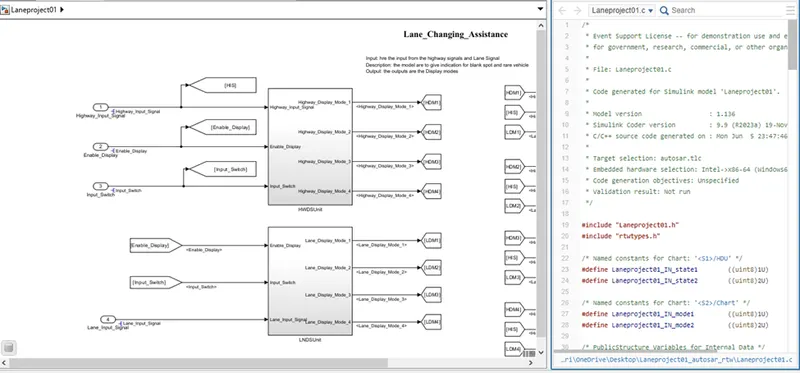
Figure. AUTOSAR Code generation
Result:
In this way, we have created Lane changing assistant feature for the driver and passenger safety during the lane change by the driver on Highway. This is a small part of the actual feature who detect the blind spots, rear cars and its speed to indicate the driver to avoid the accidental situation. The feature takes the input rom highway signal process it and produce Highway Display mode signal also produce the Lane Display mode signal from the another system and with help of switch block the it produce the appropriate output Display mode to indicate the warnings and Alerts.