Project 2 Adaptive Cruise Control
Aim:
To Create the Simulink Model project on Adaptive Cruise Control of Advance Driver Assistant System for driver and Passanger safety and Comfort.
Objective:
- Developing Adaptive Cruise Control feature as per the Requirement Document using MATLAB Simulink.
- Follow all the MBD related processes: Requirement Tagging & Traceability, SLDD creation, Configuration Parameter changes, Model Advisor check & Code Generation.
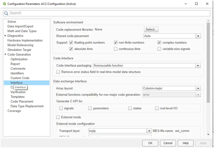
- In Configuration Parameters: enable “Support Floating Numbers” under Code Generation settings.
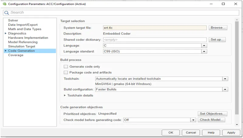
- Use Embedded Coder to generate the code.
- If choosing code generation, Storage class for Input signals: ImportedExtern; Storage class for Output signal: Export to File; Storage class for local signals: localizable; Storage class for calibration signals: Const.
- Choose sample time for all signals as 0.01s
Overview of the Project:
The Adaptive Cruise Control of the Electrical vehicle if one of the most important feature of the Advance Driver Assistant System. This feature is very useful to driven for safety control and feel comfort during the long distance driving on highway and traffic area both. There are two inputs are taken into the front drive car, one from Camera input and second from the Radar sensor. By processing this two input the front car speed can detect. Also by taking Camera input, Radar sensor and Acceleration mode input which is feedback back of the stateflow for the self drive car, the speed of the car can be automatically controlled. Here the car work on three mode of the cruise control i.e. ACC ON MODE, ACC OFF MODE and ACC STANDBY MODE.the project is developed as per the requirement given.
Simulink Model Creation:
Requirement 1– Lead Vehicle:
Step to Design Requirement 1-
- Create Subsystem and Create two inputs for CameraInput_LeadVehicle & RadarInput_LeadVehicle.
- Add input using add block.
- Create output for LeadVehicle_Speed
Requirement 1 description-
Here, two inputs are have to take for obtain the speed of Lead vehicle. So, we create two Inport block for one CamereInput_LeadVehicle & second for RadarInput_LeadVehicle. This two signal add by using the ADD block to produce the output as LeadVehicleSpeed and this is output of the requirement 1 show by outport.
Simulink Model of Requirement 1:
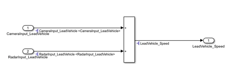
Figure 1: Lead Vehicle Speed
Requirement 2 – Drive Vehicle:
Steps to Design Requirement 2:
- Create Subsystem and Create three inputs block CameraInput_DriveVehicle, RadarInput_DriveVehicle and Acceleration_Mode
- Create two Ouput by using Outport block for DriveVehicle_Speed and LeadVehicle_Detected
- Use ADD block to sum all three to prosuce DriveVehicle_Speed ouput
- Use Signal Conversion block to produce LeadVehicle_Detected
Requirement 2 Description:
In this requirement 2, there are three input signals for the drive vehicle one for CameraInput_DriveVehicle, RadarInput_DriveVehicle and Acceleration_Mode. Create three Inport signal block and assign the name as same. There are two output signals are produce by the requirement 2 i. e. DriveVehicle_Speed and Lead Vehicle_Detected. So, to produce the DriveVehicle_Speed output use the ADD block add sum all three input. For second LeadVehicle_Detected, take signal conversion block. Connect the RadarInput_DriveVehicle signal to signal conversion block and its output port connect to output signal block and give name to it as LeadVehice_Detected.
Simulink Model of Requirement 2:
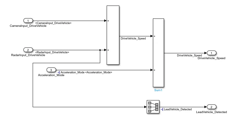
Figure: Drive Vehicle Speed & Lead Vehicle Detected
Requirement 3 – Adaptive Cruise Control Algorithm:
Steps to Solve Requirement 3:
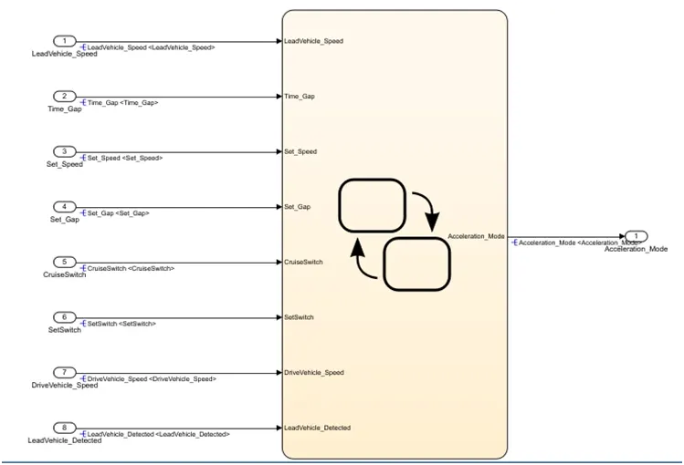
- Create the susbsystem for requirement 3 and in that create the chart to design the stateflow algorithm.
- In the stateflow chart create the three states as ACC_Off_Mode, ACC_STANDBY_Mode and ACC_On_Mode.
- Create five inputs signal named as Time_Gap, Set_Speed, Set_Gap, CruiseSwitch, SetSwitch and attach to the subsystem of requirement 3.
- Also crate the two attaché the two signals form the outputs of the requirement 2as input to the requirement 3 name as DriveVehicle_Speed and LeadVehice_Detected.
- Lastly attaché the output signal of requirement 1 to the subsystem of requirement 3 named as
- Attach the output of the requirement 3 as feedback to the requirement 2 named as Acceleration_Mode.
Requirement 3 Description:
In this Requirement we have to create the stateflow algorithm for actual flow and working of the Adaptive cruise control logic. First create the subsystem for requirement 3 and in that subsystem crate a chart. In under chart create three states for different modes and condition of the algorithm. Give the name to states as ACC_Off_Mode, ACC_STANDBY_Mode and ACC_On_Mode respectively. Creates the five input signals to subsystem or requirement 3 named as Time_Gap, Set_Speed, Set_Gap, CruiseSwitch, SetSwitch and attach to it which we will create letter into the SLDD. Attach the two signals of requirement 3 DriveVehicle_Speed and LeadVehice_Detected. Also attach the output of requirement 1 LeadVehicleSpeed. At the last we was create a input signal to requirement 2 as Acceleration_Mode and here the output of the requirement 3 is also Acceleration_Mode so we connect it as feedback to requirement 2.
Simulink Model of Requirement 3 :
Requirement 3a – ACC OFF MODE state logic:
Step to Solve Requirement 3a:
- Give the name to Crated state under the requirement 3 as ACC_Off_Mode and set the entry as Acceleration_Mode=0.
- Draw transition from ACC_Off_Mode to ACC_STANDBY_Mode and assign the condition to it as CruiseSwitch=0 and CruiseSwitch=1.
- Also draw transition from ACC_On_Mode to ACC_Off_Mode with CruiseSwitch=0 condition.
Requirement 3b – ACC STANDBY MODE state logic:
Step to Solve Requirement 3b:
- Assign the entry Acceleration_Mode=1 in this state.
- Set condition as CruiseSwitch=1, ACC_STANDBY_Mode is get activated and if CruiseSwitch=0 then ACC_STANDBY_Mode s get deactivated form standby mode and On mode mode both.
- Create transition from standby mode to On mode and assign the condition as SetSwitch=1 then ON Mode get activated and SetSwitch=0, then state standby Mode get activated.
Requirement 3c – ACC ON MODE state logic:
Steps to solve Requirement 3c:
- Create the six subsyate into the ACC ON MODE and give the to them as
- LeadVehicle_Detected_Follow (Default)
- LeadVehicle_Not_Detected
- LeadVehicle_Detected_Resume
- LeadVehicle_Not_Detected_Resume
- LeadVehicle_Speed_lessthan_Set_Speed
- LeadVehicle_Speed_equal_Set_Speed
Description of Requirement 3a, 3b and 3c:
Here, the first requirement 3a is to create the of ACC_Off_Mode. In this state we have set the Acceleration_Mode=0 by default. It is the default state. This state are governed by the input signal CruiseSwitch. we creat also anoter two state as ACC_STANDBY_Mode and ACC_On_Mode. Connect the transitionline from ACC_STANDBY_Mode to ACC_Off_Mode. Give the condition to transition as CruiseSwitch=1 then, ACC_STANDBY_Mode will get activated and CruiseSwitch=0 then ACC_Off_Mode will get activated. Also connects the transition between ACC_On_Mode and ACC_Off_Mode and set the condition as CruiseSwitch=0 then ACC_Off_Mode get activated form ACC_On_Mode. Now connect the Transition between ACC_Off_Mode to ACC_On_Mode. The control signal for this is transition is SetSwitch. If SetSwitch=1 then, ACC_On_Mode will get activated and ACC_On_Mode=0 then ACC_Off_Mode will get activate. At last create the six substate into the requirement 3c as name given above assign the name to them and give acceleration_Mode value as per requirement and Condition of transition as per requirement also.
State Model of Requirement 3a, 3b and 3c:
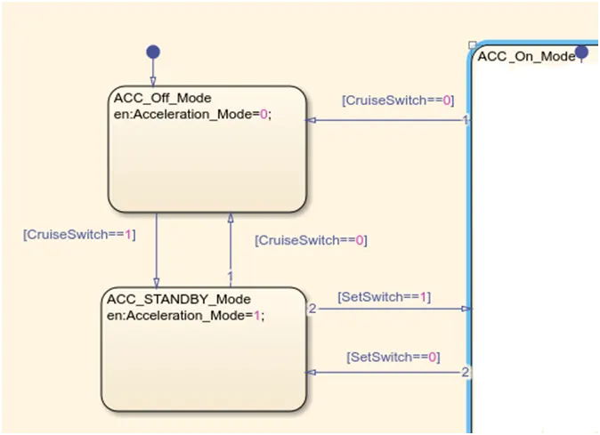
Figure: State flow model of requirement 3a, 3b, 3c
SLDD for ACC:
As per given in the requirement we have created the SLDD for the Adaptive cruise control as follows. We have set the datatype, minimum and maximum value, storage class for the Input, Output and Local signals.

Solver setting for ACC:
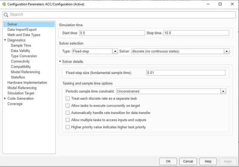
For the Solver setting of ACC we open the model configuration parameter and select the solver option from the menu. In that we have choose the starting time as 0 sec, ending time as 10 sec and Sample time as 0.01 sec.
Code Generation Setting:
For the code generation go to the model configuration setting and select the code generation tab form it. Brows the Embedded coder for the code generation and remaning parameters will automatically updated.
Requirement Tagging and Traceability:
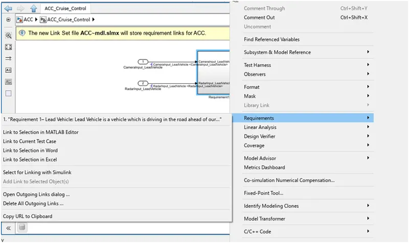
We create the different subsystem as per the different requirement given to us. For the requirement linking we select the requirement form the requirement word sheet and right click select the requirement tab and click on link requirement word sheet. Same process follow for all subsystems of the model.
Support Floating Setting:
Actually the support floating setting is get automatically activated when we select the code generation setting and Embedded coder. For that go to model configuration setting and select the Interface from the menu. Check whether the support floating check box is selected or not. If not then select it.
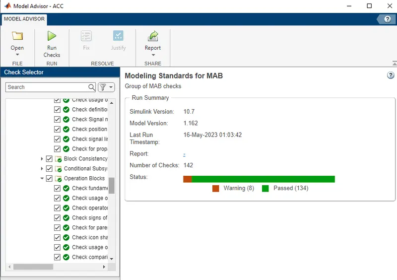
Model Advisory Check:
Complete Simulink model of the Project:
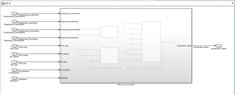
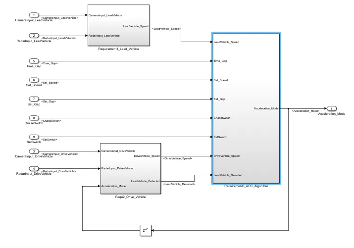
Figure: Adaptive Cruise Control Simulink Model
Result: In this way we have Developed the Adaptive Cruise control Simulink model of Advance Driver Assistant System for Driver and Passenger Safety and Comfort. this Adaptive cruise control feature are able to avoid the accident by controlling the drive car speed on the basis of lead car speed. the driver here able to set manually variour parameter regarding to this ACC feature like Time Gap, Distance between both card, Set speed any many more as per his own choice. this feature warn to driver when it detect the upcoming car within its radar range, if driver unable to stop it then automatically car apply the breack and slow down the speed. this Adaptive Cruse Control also known as Radar cruse control, Automotive cruise control.this feacture sense the front vehicle position from the drive vehicle with the help of Camera input and Radar input also current driving speed of self drive car. with the help of stateflow machine Algorith is develop here for working the ACC into On mode, Off mode and Standby mode. it is also posible here that driver can manually activate and deactivate the feature. In this war we have complited this project after checking model advisory report and code generation.