Project 1- Traffic Jam Assistant Feature
Aim: To develop the Simulation model project on Traffic Jam Assistant feature.
Objective:
- To develop Simulink model as per requirement for Traffic jam Assistant feature.
- Create SLDD and link with Simulink model.
- Make solver setting, Code setting.
- Check MAAB guideline and model advisory report.
Description:
The Traffic jam assistant feature is one of the feature of Advance driver assistant feature. This feature help to driver to indicate the traffic status during the travelling and suggest the low traffic road to reach the destination and also save the fuel cost. This feature can be ON/ OFF by the driver in which the steering, break and accelerator control can be control by vehicle or driver.
In this Simulink model, it is based on the concept of lane keeping support. This support is obtained by the sensor which detect the surrounding vehicles speed. If the vehicle found the traffic / lead vehicle have speed less than normal running then it control the break, acceleration and steering control actively and warn to driver also. The notification regarding the traffic jam is display on the instrument panel cluster.
Requirement 1:
Steps to develop requirement 1
- Insert inport signals named as ‘Input_Voltage’, and two compare to constant blocks for ‘VOLTAGE_MINIMUM_RANGE’, ‘VOLTAGE_MAXIMUM_RANGE’.
- Connect the Input_Voltage’ to two constant blocks of ‘VOLTAGE_MINIMUM_RANGE’, ‘VOLTAGE_MAXIMUM_RANGE’.
- inssert AND block for two outputs of this constant blocks. And import outport block as outpout of AND block named as ‘Optimum_Voltage’.
Description:
For the requirement 1 , we have input as ‘Input voltage;, this voltage we have to gived to two range of the voltages with compare to constant blocks. We set the limit as less than or equal to for ‘Voltage maximum Range’ and greater than or equal to for’ Voltage minimum range’. Then , we joint this output of two constant blocks to AND block. The output of the AND get is take as ‘ Optimum Voltage’ which is the input to a second requirement of the vehicle.
Simulink model of Requirement 1:
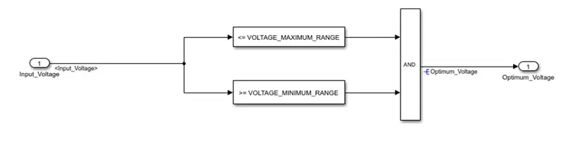
Figure 1: Requirement 1 model
Requirement 2: Display Unit Subsystem
Steps for requirement 2:
- take output signal of requiremtn 1 as one input to display system and also create two inport signals as ‘Input_Switch’, and ‘Enable_Display’.
- Connect the saturation block with 0-7 range for Enable Display signal and create outport signal as output of display system as ‘Output_Display’.
- Insert multiport switch switch with 5 input for compare with Enable Display.
- Insert constant block with named as ‘ON_MODE’ and connect to multiport switch 1&2. Same way for 3& 4 insert and connect as ‘OFF_MODE’ and 5 is for ‘STANDBY_MODE’.
- Insert switch block and fed the multiport switch output to first input of switch block.
- Insert constant block named as ‘NO_DISPLAY’ and connect to the third output of ‘switch block’.
- Connect the NOT gate to ‘Input_Switch’ signal and compare it with optimum voltage from requirement 1.
- Create two constant blocks ‘INTERRUPT_1’ and ‘INTERRUPT_2’ and compare it with compare blocks. The output of this compare block is connect to AND block & also step 7 output connect to this AND block.
- The output of above AND block connect to the second input of switch block and finally take outport signal ‘Output_Display’ as final output of the requirement 2.
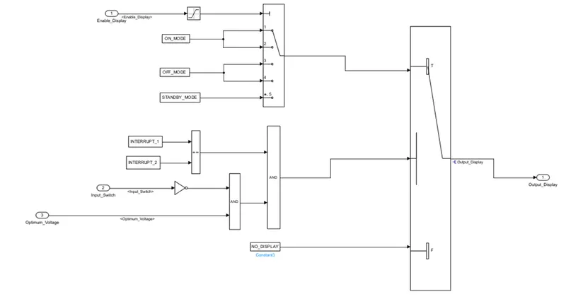
Figure 2: Requirement 2 model
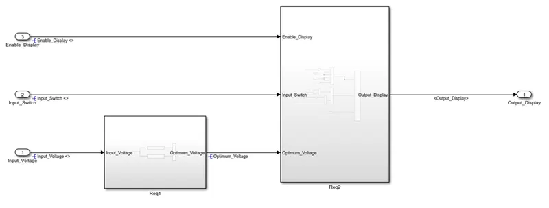
Figure 3: common model of both requirements
Main model with signal resolving and propagation:
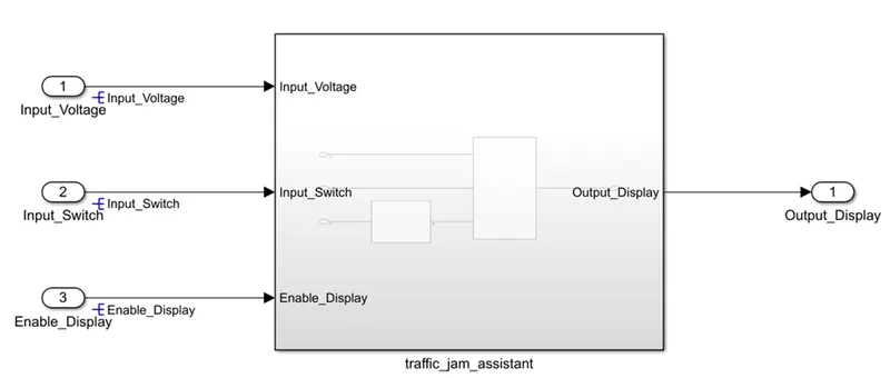
Figure: signal propagation
Code generation setting as embedded coder:
First we have set the solver setting for the model. Here start time , end time and sample time is set. For the code generation we select the Embedded coder.
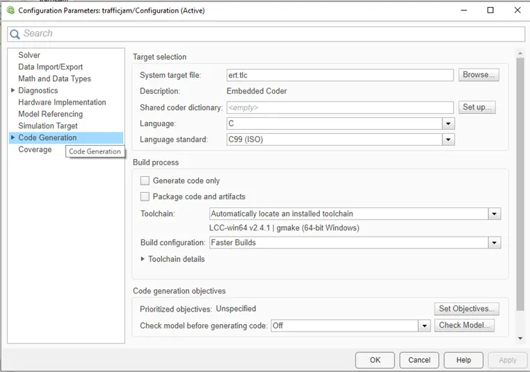
Figure: Embedded coder setting
SLDD creation and linking:
The Simulink data dictionary is crated as per the given in the requirement document. Here storage class is given as for input signal importexter, for output signal as exporttofile and for the parameter as const. one local signal is also present.
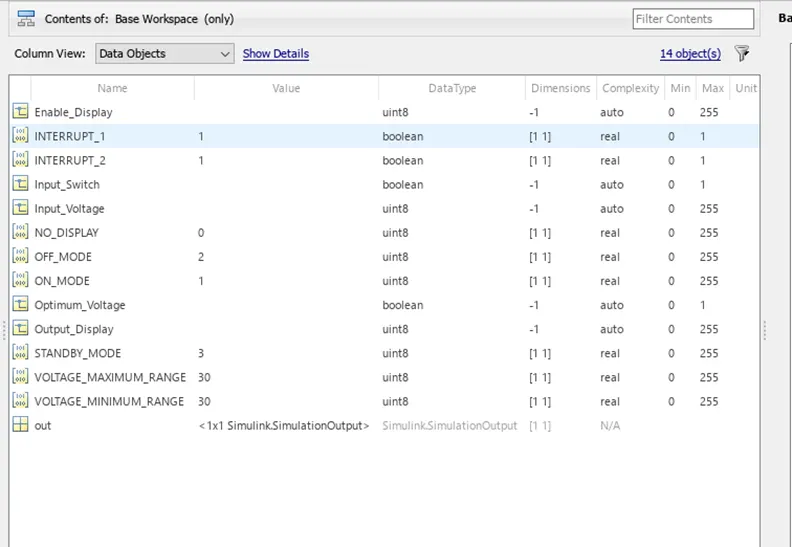
Figure: SLDD linking
Requirement Tagging:
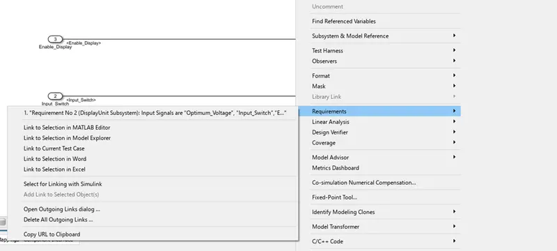
Model Advisory checks as per MAAB:
The model advisory check perform to see whether out Simulink model is generated as per the MAAB guideline. If necessary action is needed after the run we correct it as per the suggestion and finally generate the model advisory report.
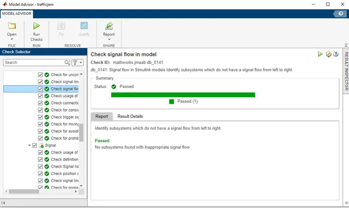
Figure: Model advisory check
Code generation:
For the code generation, we select the ‘app’ from the upper task bar and select the Embedded coder icon. After that click on ‘Build’ icon select generate code to generate the code for the Simulink model.
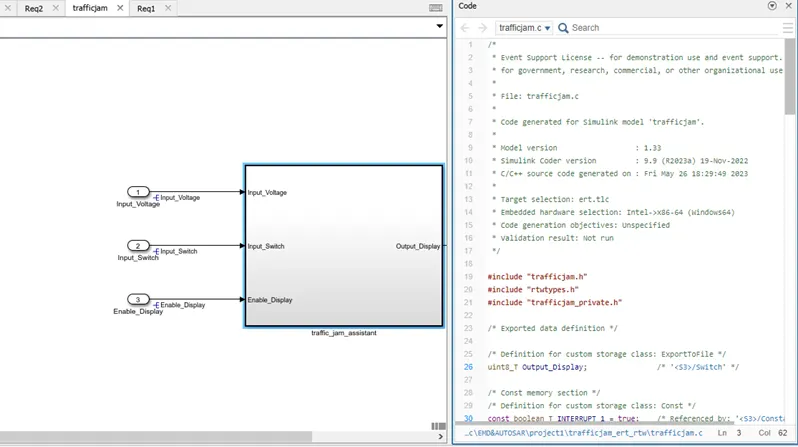
Figure: code generation Simulink model
Result: in this way, we have created the Simulink model for the Traffic jam Assistant feature for the display message to driver to indicate the current road traffic status and driver comfort. also, we have performed MAAB checks, solver setting, code generation setting as embedded coder. generate code and model advisory report.